ScienceDirect
Available online at www.sciencedirect.com
Procedia Engineering 207 (2017) 1230–1235
1877-7058 © 2017 The Authors. Published by Elsevier Ltd.
Peer-review under responsibility of the scientific committee of the International Conference on the Technology of Plasticity. 10.1016/j.proeng.2017.10.875
10.1016/j.proeng.2017.10.875
© 2017 The Authors. Published by Elsevier Ltd.
Peer-review under responsibility of the scientific committee of the International Conference on the Technology of Plasticity.
1877-7058 Available online at www.sciencedirect.com
ScienceDirect
Procedia Engineering 00 (2017) 000–000
www.elsevier.com/locate/procedia
1877-7058 © 2017 The Authors. Published by Elsevier Ltd.
Peer-review under responsibility of
the scientific committee of the International Conference on the Technology of
Plasticity
..
International Conference on the Technology of Plasticity, ICTP 2017, 17-22 September 2017,
Cambridge, United Kingdom
Driver roll speed influence in Ring Rolling process
G.Allegri
a,*, L.Giorleo
a, E.Ceretti
a, C.Giardini
baUniversity of Brescia, Department of Mechanical and Industrial Engineering, Via Branze 38, 25123 Brescia, Italy
b University of Bergamo, Department of Management, Information and Production Engineering, Via Marconi 5, 24044 Dalmine (BG), Italy
Abstract
Ring Rolling is an advanced local incremental forming technology to fabricate directly precise seamless ring-shape parts with various dimensions and materials. To produce a high-quality ring different speed laws should be defined: the speed laws of the Idle and Axial rolls must be set to control the ring cross section and the Driver roll angular velocity must be chosen to avoid too high localized deformation on the ring cross section.
Usually, in industrial environment, a constant rotation is set for the Driver roll, but this approach does not guarantee a constant ring angular velocity because of its diameter expansion. In particular, the higher is the ring diameter the lower is its angular velocity. The main risk due to this constrain is the generation of a non-uniform ring geometry. An innovative approach is to design a Driver Roll speed law to obtain a constant ring angular velocity.
In this paper a FEM approach was followed to investigate the Driver roll speed influence on the Ring Rolling process. Different Driver roll speed laws were tested starting from a model defined in an industrial plant. Results will be analyzed by a geometrical and physical point of view.
© 2017 The Authors. Published by Elsevier Ltd.
Peer-review under responsibility of
the scientific committee of the International Conference on the Technology
of Plasticity
.Keywords: Ring Rolling, Driver Roll angular velocity, FEM
* Corresponding author. Tel.: +39-030-3715538; fax: +39-0303702448. E-mail address: [email protected]
Available online at www.sciencedirect.com
ScienceDirect
Procedia Engineering 00 (2017) 000–000
www.elsevier.com/locate/procedia
1877-7058 © 2017 The Authors. Published by Elsevier Ltd.
Peer-review under responsibility of
the scientific committee of the International Conference on the Technology of
Plasticity
..
International Conference on the Technology of Plasticity, ICTP 2017, 17-22 September 2017,
Cambridge, United Kingdom
Driver roll speed influence in Ring Rolling process
G.Allegri
a,*, L.Giorleo
a, E.Ceretti
a, C.Giardini
baUniversity of Brescia, Department of Mechanical and Industrial Engineering, Via Branze 38, 25123 Brescia, Italy
b University of Bergamo, Department of Management, Information and Production Engineering, Via Marconi 5, 24044 Dalmine (BG), Italy
Abstract
Ring Rolling is an advanced local incremental forming technology to fabricate directly precise seamless ring-shape parts with various dimensions and materials. To produce a high-quality ring different speed laws should be defined: the speed laws of the Idle and Axial rolls must be set to control the ring cross section and the Driver roll angular velocity must be chosen to avoid too high localized deformation on the ring cross section.
Usually, in industrial environment, a constant rotation is set for the Driver roll, but this approach does not guarantee a constant ring angular velocity because of its diameter expansion. In particular, the higher is the ring diameter the lower is its angular velocity. The main risk due to this constrain is the generation of a non-uniform ring geometry. An innovative approach is to design a Driver Roll speed law to obtain a constant ring angular velocity.
In this paper a FEM approach was followed to investigate the Driver roll speed influence on the Ring Rolling process. Different Driver roll speed laws were tested starting from a model defined in an industrial plant. Results will be analyzed by a geometrical and physical point of view.
© 2017 The Authors. Published by Elsevier Ltd.
Peer-review under responsibility of
the scientific committee of the International Conference on the Technology
of Plasticity
.Keywords: Ring Rolling, Driver Roll angular velocity, FEM
* Corresponding author. Tel.: +39-030-3715538; fax: +39-0303702448. E-mail address: [email protected]
2 Gabriele Allegri/ Procedia Engineering 00 (2017) 000–000
1. Introduction
In Ring Rolling process the metal is rolled between two couple of rolls [1,2]: two radial and two axial. In each couple, one roll moves toward the other one to reduce ring width and height; during the process due to the volume compensation diameter expansion occurs. This process is for the production of railway wheels, anti-friction bearings and different ring shaped workpieces for automotive, aerospace and wind industry applications. It can be both a hot or cold [3] process and different alloys as steels, light and titanium alloys can be worked [4]. The advantages of Ring Rolling process include: short production time, uniform quality, close tolerances and considerable saving in material cost. This process, compared to others as casting or plasma cutting, guarantees lower working temperatures, less required material and, consequently, a reduction in energy consumption. Moreover, the main advantage of the Ring Rolling product is given by the size and orientation of grains, especially on the worked surface which guarantee to the final product excellent mechanical properties.
Fig. 1a summarizes the Ring Rolling process: the Idle Roll forces an hollow circular preform against a Driver roll on the Y direction. At the same time, the Axial rolls apply a pressure in Z direction. A backward movement on the Y-axis is given to the Axial rolls according to the diameter expansion. Because the ring does not rotate on its own Y-axis, two Guide rolls are designed to assure the stability of the process. Therefore, in a Ring Rolling process the following parameters must be defined:
• the Idle and Axial rolls speed laws respectively along the Y and Z directions to control the ring cross section; • the Driver roll angular velocity, that must be set accordingly to Idle and Axial roll speed laws to avoid
excessive ring deformation in the cross section;
• the Axial roll speed law along the Y direction accordingly to the ring expansion; • the Guide rolls speed law for the stability of the process.
The displacement of each roll can be set independently from the others. For this reason, in industrial practice the milling curve is introduced as a function of the instantaneous ring height (H) and width (W) (Fig. 1b).
a) b)
Fig. 1.a) Ring Rolling scheme; b) Milling curve for a Ring Rolling process
The milling curve definition is fundamental to guarantee a correct ring production [5-8]: by imposing an optimized curve it is possible to reduce rolls load [9] and production times while ensuring a correct ring geometry avoiding the fishtail defect [10].
Usually the studies focused on Ring Rolling, consider constant Driver Roll’s angular speed (namely Standard Configuration). This means that the angular velocity of the ring decreases as a function of the growth of the external diameter; this can lead to general deformation problems such as fishtail, local deformations of the ring that produce errors on the external diameter (Dext), height (H) and width (W). In literature, there are limited works about the
influence of the Driver Roll on the process [11]. In the present work, a FEM approach has been used in order to investigate the influence of different non-constant Driver Roll rotation laws. The aim was to verify if a constant ring
Z Y X
G. Allegri et al. / Procedia Engineering 207 (2017) 1230–1235 1231 Available online at www.sciencedirect.com
ScienceDirect
Procedia Engineering 00 (2017) 000–000
www.elsevier.com/locate/procedia
1877-7058 © 2017 The Authors. Published by Elsevier Ltd.
Peer-review under responsibility of
the scientific committee of the International Conference on the Technology of
Plasticity
..
International Conference on the Technology of Plasticity, ICTP 2017, 17-22 September 2017,
Cambridge, United Kingdom
Driver roll speed influence in Ring Rolling process
G.Allegri
a,*, L.Giorleo
a, E.Ceretti
a, C.Giardini
baUniversity of Brescia, Department of Mechanical and Industrial Engineering, Via Branze 38, 25123 Brescia, Italy
b University of Bergamo, Department of Management, Information and Production Engineering, Via Marconi 5, 24044 Dalmine (BG), Italy
Abstract
Ring Rolling is an advanced local incremental forming technology to fabricate directly precise seamless ring-shape parts with various dimensions and materials. To produce a high-quality ring different speed laws should be defined: the speed laws of the Idle and Axial rolls must be set to control the ring cross section and the Driver roll angular velocity must be chosen to avoid too high localized deformation on the ring cross section.
Usually, in industrial environment, a constant rotation is set for the Driver roll, but this approach does not guarantee a constant ring angular velocity because of its diameter expansion. In particular, the higher is the ring diameter the lower is its angular velocity. The main risk due to this constrain is the generation of a non-uniform ring geometry. An innovative approach is to design a Driver Roll speed law to obtain a constant ring angular velocity.
In this paper a FEM approach was followed to investigate the Driver roll speed influence on the Ring Rolling process. Different Driver roll speed laws were tested starting from a model defined in an industrial plant. Results will be analyzed by a geometrical and physical point of view.
© 2017 The Authors. Published by Elsevier Ltd.
Peer-review under responsibility of
the scientific committee of the International Conference on the Technology
of Plasticity
.Keywords: Ring Rolling, Driver Roll angular velocity, FEM
* Corresponding author. Tel.: +39-030-3715538; fax: +39-0303702448. E-mail address: [email protected]
Available online at www.sciencedirect.com
ScienceDirect
Procedia Engineering 00 (2017) 000–000
www.elsevier.com/locate/procedia
1877-7058 © 2017 The Authors. Published by Elsevier Ltd.
Peer-review under responsibility of
the scientific committee of the International Conference on the Technology of
Plasticity
..
International Conference on the Technology of Plasticity, ICTP 2017, 17-22 September 2017,
Cambridge, United Kingdom
Driver roll speed influence in Ring Rolling process
G.Allegri
a,*, L.Giorleo
a, E.Ceretti
a, C.Giardini
baUniversity of Brescia, Department of Mechanical and Industrial Engineering, Via Branze 38, 25123 Brescia, Italy
b University of Bergamo, Department of Management, Information and Production Engineering, Via Marconi 5, 24044 Dalmine (BG), Italy
Abstract
Ring Rolling is an advanced local incremental forming technology to fabricate directly precise seamless ring-shape parts with various dimensions and materials. To produce a high-quality ring different speed laws should be defined: the speed laws of the Idle and Axial rolls must be set to control the ring cross section and the Driver roll angular velocity must be chosen to avoid too high localized deformation on the ring cross section.
Usually, in industrial environment, a constant rotation is set for the Driver roll, but this approach does not guarantee a constant ring angular velocity because of its diameter expansion. In particular, the higher is the ring diameter the lower is its angular velocity. The main risk due to this constrain is the generation of a non-uniform ring geometry. An innovative approach is to design a Driver Roll speed law to obtain a constant ring angular velocity.
In this paper a FEM approach was followed to investigate the Driver roll speed influence on the Ring Rolling process. Different Driver roll speed laws were tested starting from a model defined in an industrial plant. Results will be analyzed by a geometrical and physical point of view.
© 2017 The Authors. Published by Elsevier Ltd.
Peer-review under responsibility of
the scientific committee of the International Conference on the Technology
of Plasticity
.Keywords: Ring Rolling, Driver Roll angular velocity, FEM
* Corresponding author. Tel.: +39-030-3715538; fax: +39-0303702448. E-mail address: [email protected]
2 Gabriele Allegri/ Procedia Engineering 00 (2017) 000–000
1. Introduction
In Ring Rolling process the metal is rolled between two couple of rolls [1,2]: two radial and two axial. In each couple, one roll moves toward the other one to reduce ring width and height; during the process due to the volume compensation diameter expansion occurs. This process is for the production of railway wheels, anti-friction bearings and different ring shaped workpieces for automotive, aerospace and wind industry applications. It can be both a hot or cold [3] process and different alloys as steels, light and titanium alloys can be worked [4]. The advantages of Ring Rolling process include: short production time, uniform quality, close tolerances and considerable saving in material cost. This process, compared to others as casting or plasma cutting, guarantees lower working temperatures, less required material and, consequently, a reduction in energy consumption. Moreover, the main advantage of the Ring Rolling product is given by the size and orientation of grains, especially on the worked surface which guarantee to the final product excellent mechanical properties.
Fig. 1a summarizes the Ring Rolling process: the Idle Roll forces an hollow circular preform against a Driver roll on the Y direction. At the same time, the Axial rolls apply a pressure in Z direction. A backward movement on the Y-axis is given to the Axial rolls according to the diameter expansion. Because the ring does not rotate on its own Y-axis, two Guide rolls are designed to assure the stability of the process. Therefore, in a Ring Rolling process the following parameters must be defined:
• the Idle and Axial rolls speed laws respectively along the Y and Z directions to control the ring cross section; • the Driver roll angular velocity, that must be set accordingly to Idle and Axial roll speed laws to avoid
excessive ring deformation in the cross section;
• the Axial roll speed law along the Y direction accordingly to the ring expansion; • the Guide rolls speed law for the stability of the process.
The displacement of each roll can be set independently from the others. For this reason, in industrial practice the milling curve is introduced as a function of the instantaneous ring height (H) and width (W) (Fig. 1b).
a) b)
Fig. 1.a) Ring Rolling scheme; b) Milling curve for a Ring Rolling process
The milling curve definition is fundamental to guarantee a correct ring production [5-8]: by imposing an optimized curve it is possible to reduce rolls load [9] and production times while ensuring a correct ring geometry avoiding the fishtail defect [10].
Usually the studies focused on Ring Rolling, consider constant Driver Roll’s angular speed (namely Standard Configuration). This means that the angular velocity of the ring decreases as a function of the growth of the external diameter; this can lead to general deformation problems such as fishtail, local deformations of the ring that produce errors on the external diameter (Dext), height (H) and width (W). In literature, there are limited works about the
influence of the Driver Roll on the process [11]. In the present work, a FEM approach has been used in order to investigate the influence of different non-constant Driver Roll rotation laws. The aim was to verify if a constant ring
Z Y X
1232 Gabriele Allegri/ Procedia Engineering 00 (2017) 000–000 G. Allegri et al. / Procedia Engineering 207 (2017) 1230–1235 3
rotation (namely New Configuration) can generate benefits in terms of the geometry of the ring and forces acting on the milling plant.
2 Numerical set up
For this work Deform 3D FEM software was used. First, a simulation of a Ring Rolling Standard Configuration was performed. The main characteristics of the ring and the rolls are summarized in Table 1. The simulation is limited to model half ring considering the symmetry on the XY plane; the rolls were considered as rigid bodies and tetrahedral mesh was used with 10680 elements for the preform. A friction factor of 0.7 was imposed between the rolls and the preform and no heat exchange was set. This simulation imposes a constant Driver Roll angular velocity (𝜔𝜔1), that leads to a decreasing angular velocity of the ring (𝜔𝜔2), as shown in Fig. 2a. Fig. 2b shows the milling curve for this process. In particular, the Idle and Axial rolls speed laws are defined.
Table 1: Ring and rolls dimensions and characteristics
H[mm] W[mm] Dext [mm]
Preform 75 69 258
Finished ring 56 50 373
Material AISI 1045
Workpiece Temperature 1150 ° C
Milling time 16.8 sec
a) b)
Fig. 2. a) Angular velocities for Standard Configuration; b) Diameter expansion.
Idle Roll Diameter [mm] 110
Driving Roll Diameter [mm] 700
Driving Roll angular velocity [rad/sec] 3.35
Axial Roll Height [mm] 400
Axial Roll taper angle [°] 15.7
4 Gabriele Allegri/ Procedia Engineering 00 (2017) 000–000
Since the peripheral velocity at the contact point between the Driver Roll and the ring is the same, Equation 1 has been used for calculating the Driver roll law guarantying a constant ring angular velocity.
∅1 ∙ 𝜔𝜔1 = ∅2 ∙ 𝜔𝜔2 (1) Being: ∅1=External diameter of the ring;
∅2=Diameter of the Driver roll; 𝜔𝜔1=Angular velocity of the ring; 𝜔𝜔2=Angular velocity of the Driver roll.
Where the external ring diameter was evaluated based on the constant volume constrain coupled with the milling curve equation (fig. 3.b)
a) b)
Fig. 3. a) Angular velocities for New Configuration; b) Diameter expansion of the ring
As it can be seen in Figure 3.a, the New Configuration assures a constant angular velocity of the ring equal to 9.27 Rad/s. In order to investigate the effect of the ring rotational speed, a total of 5 different simulations have been set considering two models with lower 𝜔𝜔1 (2.77 and 6.91 Rad/s namely Test A and B) and two models with higher (13.83 and 27.64 Rad/s namely Test C and D). By using Equation 2 the 𝜔𝜔2 expressions have been derived as reported in Table 2.
Table 2: Details of the simulations performed
Test Driver Roll Angular Velocity Rad/s 𝜔𝜔2 Ring Angular Velocity Rad/s 𝜔𝜔1
Standard Configuration 3.35 0.3285𝑡𝑡2+ 1.6768𝑡𝑡 + 2582391.9 New Configuration 0.0042𝑡𝑡2+ 0.0217𝑡𝑡 + 3.3496 9.27 Test A 0.0012𝑡𝑡2+ 0.0064𝑡𝑡 + 0.9998 2.77 Test B 0.0031𝑡𝑡2+ 0.0162𝑡𝑡 +2.4968 6.91 Test C 0.0063𝑡𝑡2+ 0.0324𝑡𝑡 +4.9973 13.83 Test D 0.0127𝑡𝑡2+ 0.0649𝑡𝑡 +9.9875 27.64
For evaluating the rings quality, often geometrical comparisons between the external diameters, heights and widths were performed. The fishtail defect, defined as the difference between the maximum and minimum ring height in correspondence of the Idle and Driver rolls was measured too. The physical parameters were analyzed taking into
G. Allegri et al. / Procedia Engineering 207 (2017) 1230–1235 1233
Gabriele Allegri/ Procedia Engineering 00 (2017) 000–000 3
rotation (namely New Configuration) can generate benefits in terms of the geometry of the ring and forces acting on the milling plant.
2 Numerical set up
For this work Deform 3D FEM software was used. First, a simulation of a Ring Rolling Standard Configuration was performed. The main characteristics of the ring and the rolls are summarized in Table 1. The simulation is limited to model half ring considering the symmetry on the XY plane; the rolls were considered as rigid bodies and tetrahedral mesh was used with 10680 elements for the preform. A friction factor of 0.7 was imposed between the rolls and the preform and no heat exchange was set. This simulation imposes a constant Driver Roll angular velocity (𝜔𝜔1), that leads to a decreasing angular velocity of the ring (𝜔𝜔2), as shown in Fig. 2a. Fig. 2b shows the milling curve for this process. In particular, the Idle and Axial rolls speed laws are defined.
Table 1: Ring and rolls dimensions and characteristics
H[mm] W[mm] Dext [mm]
Preform 75 69 258
Finished ring 56 50 373
Material AISI 1045
Workpiece Temperature 1150 ° C
Milling time 16.8 sec
a) b)
Fig. 2. a) Angular velocities for Standard Configuration; b) Diameter expansion.
Idle Roll Diameter [mm] 110
Driving Roll Diameter [mm] 700
Driving Roll angular velocity [rad/sec] 3.35
Axial Roll Height [mm] 400
Axial Roll taper angle [°] 15.7
4 Gabriele Allegri/ Procedia Engineering 00 (2017) 000–000
Since the peripheral velocity at the contact point between the Driver Roll and the ring is the same, Equation 1 has been used for calculating the Driver roll law guarantying a constant ring angular velocity.
∅1 ∙ 𝜔𝜔1 = ∅2 ∙ 𝜔𝜔2 (1) Being: ∅1=External diameter of the ring;
∅2=Diameter of the Driver roll; 𝜔𝜔1=Angular velocity of the ring; 𝜔𝜔2=Angular velocity of the Driver roll.
Where the external ring diameter was evaluated based on the constant volume constrain coupled with the milling curve equation (fig. 3.b)
a) b)
Fig. 3. a) Angular velocities for New Configuration; b) Diameter expansion of the ring
As it can be seen in Figure 3.a, the New Configuration assures a constant angular velocity of the ring equal to 9.27 Rad/s. In order to investigate the effect of the ring rotational speed, a total of 5 different simulations have been set considering two models with lower 𝜔𝜔1 (2.77 and 6.91 Rad/s namely Test A and B) and two models with higher (13.83 and 27.64 Rad/s namely Test C and D). By using Equation 2 the 𝜔𝜔2 expressions have been derived as reported in Table 2.
Table 2: Details of the simulations performed
Test Driver Roll Angular Velocity Rad/s 𝜔𝜔2 Ring Angular Velocity Rad/s 𝜔𝜔1
Standard Configuration 3.35 0.3285𝑡𝑡2+ 1.6768𝑡𝑡 + 2582391.9 New Configuration 0.0042𝑡𝑡2+ 0.0217𝑡𝑡 + 3.3496 9.27 Test A 0.0012𝑡𝑡2+ 0.0064𝑡𝑡 + 0.9998 2.77 Test B 0.0031𝑡𝑡2+ 0.0162𝑡𝑡 +2.4968 6.91 Test C 0.0063𝑡𝑡2+ 0.0324𝑡𝑡 +4.9973 13.83 Test D 0.0127𝑡𝑡2+ 0.0649𝑡𝑡 +9.9875 27.64
For evaluating the rings quality, often geometrical comparisons between the external diameters, heights and widths were performed. The fishtail defect, defined as the difference between the maximum and minimum ring height in correspondence of the Idle and Driver rolls was measured too. The physical parameters were analyzed taking into
1234 Gabriele Allegri/ Procedia Engineering 00 (2017) 000–000 G. Allegri et al. / Procedia Engineering 207 (2017) 1230–1235 5
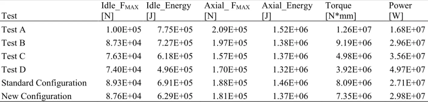
account the maximum Idle, Axial loads and the Driver Roll torque and the power reached during the deformation. The Idle and Axial energy required to carry out the process were also considered.
3 Finite Element results
All the FEM investigated parameters were analized in order to identify the optimal speed law in terms of both the final geometry of the ring and the production forces. In particular, Table 3 shows the geometry of the ring obtained at the end of each Test, while Table 4 reports the phisical parameters. Since the FEM software considers a constant volume of the ring, the external diameter is always (except for Test A in which the resulting ring has a non homogeneus geometry) bigger than the one obtained in the industrial process. This can be explained considering the material lost during the actual process due to oxidation of the external surface of the ring. For this reason, the quality of the final geometry of the ring was considered in terms of the dispersion of the geometrical parameters H and W (
σ
H andσ
W). The related fishtail defect was analized too.Table 3: Geometrical results
Test Dext [mm] H [mm]
σ
H W[mm]σ
W Fishtail [mm]Test A 347.86 28.66 1.014 55.20 1.396 1.88 Test B 377.51 27.89 0.519 54.38 0.462 0.99 Test C 380.94 27.54 0.234 54.04 0.149 0.55 Test D 383.66 27.40 0.127 53.88 0.051 0.43 Standard Configuration 378.01 27.86 0.483 54.475 0.631 0.86 New Configuration 378.01 27.65 0.301 54.14 0.181 0.56
Table 4: Physical results
Test Idle_F[N] MAX Idle_Energy [J] Axial_ F[N] MAX Axial_Energy [J] Torque [N*mm] Power [W]
Test A 1.00E+05 7.75E+05 2.09E+05 1.52E+06 1.26E+07 1.68E+07
Test B 8.73E+04 7.27E+05 1.97E+05 1.38E+06 9.19E+06 2.96E+07
Test C 7.63E+04 6.18E+05 1.57E+05 1.37E+06 4.98E+06 3.56E+07
Test D 7.40E+04 4.96E+05 1.70E+05 1.32E+06 3.92E+06 4.97E+07
Standard Configuration 8.93E+04 6.91E+05 1.88E+05 1.46E+06 8.09E+06 2.71E+07
New Configuration 8.76E+04 6.29E+05 1.81E+05 1.37E+06 7.35E+06 2.98E+07
Results show that the New Configuration produces a ring with better geometry compared to the Standard Configuration. In particular, the dispersion of the height (
σ
H) and the width (σ
W) of the ring is reduced. Tests A andB produce a geometry of the ring characterized by higher dispersion of the data compared to the New Configuration suggesting that an angular velocity of the ring lower than 7 Rad/s is not enough for a correct ring milling. On the other hand, Tests C and D result in a lower standard deviation values of both height and width of the ring compared to the other Tests. In particular Test D is the best configuration assuming the more homogenous ring. Concerning the physical parameters, comparing Standard and New Configurations, it is evident that the maximum forces and energies on the Idle Roll, Axial Roll and on the Torque of the Driver Roll decrease in comparison with the Standard Configuration. Considering the others Tests, it is possible to see how increasing the angular velocity of the Driver Roll leads to a reduction of the forces and energies acting on the rolls, although there is an increasing in the power spent by the Driver Roll. Figure 6 reports the comparison between the fishtail defect for the Standard Configuration and Test D. It is possible to verify that Test D results in a reduction of the defect of 50%
6 Gabriele Allegri/ Procedia Engineering 00 (2017) 000–000
.
Fig.4. Fishtail defect in Test D and Standard Configuration 4 Conclusions
The aim of this work was to investigate the influence of different non-constant Driver Roll rotation laws on the Ring Rolling process. In a Standard Configuration of the process, the angular velocity of the Driver Roll is set as constant causing the decrease of the angular velocity of the ring. This effect leads to the generation of local geometrical defects as the fishtail artifact and a high deviation of the heights and the widths of the produced rings.
To overcome this limitation, a finite element model has been used to verify if a constant angular velocity of the ring can generate benefits in terms of final geometry of the ring and forces generated on the milling plant. Five different rotational speeds have been considered to analyze their effect on the produced ring. The results showed that the New Configuration is able to reduce both the deviation of the geometrical data (
σ
H andσ
W) and the fishtail defect(reduction of 35 %) compared to the Standard Configuration. Moreover, an angular velocity of the ring lower than 7 Rad/s is not enough for a correct ring milling. On the other hand, an angular velocity of the Driver Roll of 10 Rad/s can lead to a more homogenous geometry of the ring and a reduction of the forces and energies acting on the rolls. In conclusion, the proposed finite element model can be used to identify the optimal configuration of a Ring Rolling process that ensures low deviations of the geometrical parameters with an optimization of the forces acting on the milling plant with 2 variable Driver roll angular speeds.
References
[1] Eruc E, Shivpuri R (1992) A summary of ring rolling technology —I. Recent trends in machines, processes and production lines. International Journal of Machine Tools and Manufacturing 32:379–98.
[2] Allwood JM, Tekkaya AE, Stanistreet TF (2005) The development of ring rolling technology. Steel Research International 76:111–20. [3] GUO Ling-gang, YANG He, ZHAN Mei. Research on plastic deformation bheavior in cold ring rolling by FEM numerical simulation [J]. Modeling and Simulation in Material Science and Engineering, 2005, 13: 1029-1046.
[4] Yan FL, Hua L, Wu YQ (2007) Planning feed speed in cold ring rolling. International Journal of Machine Tools and Manufacturing 47:1695– 701.
[5] Giorleo L., Ceretti E., Giardini C. (2016). Idle and axial roll speed law trend effect in an industrial ring rolling process, AIP Conference Proceeding, 1769:130006-1–130006-6;
[6] Giorleo L., Ceretti E., Giardini C. (2015) Speed Idle Roll law optimization in a Ring Rolling process, Key Engineering Materials, Vols 651-653:248-253.
[7] Giorleo L., Ceretti E., Giardini C., (2014) Milling curves influence in Ring Rolling processes, Key Engineering Materials, 622-623:956-963; [8] Giorleo L., Ceretti E., Giardini C. (2013) Speed Roll laws influence in a Ring Rolling process, Key Engineering Materials, 554-557:337-344; [9] Giorleo L., Ceretti E., Giardini C. (2013) Energy consumption reduction in Ring Rolling processes: A FEM analysis. International Journal of Mechanical Sciences Volume 74, September 2013, Pages 55-64.
[10] Giorleo L, Ceretti E, Giardini C (2012) Investigation of the Fishtail Defect in Ring Rolling by a FEM Approach. Proceedings of NAMRI/SME Society of Manufacturing Engineers. 2014.
[11] Xiaodong Luo, Lianjie Li, Wenlin Xu, Yongxiang Zhu (2014). Effect of driver rotational speed on hot ring rolling of AZ31 magnesium alloy. Journal of Magnesium and alloys/2213-9567.
[12]Li, L.J., Luo, X.D., Zhu, Y.X.. Effects of rotational speed of driver roll on hot ring rolling of 6061 aluminum alloy by 3D FE simulation, Advanced Materials Research, 2015, 309-315
G. Allegri et al. / Procedia Engineering 207 (2017) 1230–1235 1235
Gabriele Allegri/ Procedia Engineering 00 (2017) 000–000 5
account the maximum Idle, Axial loads and the Driver Roll torque and the power reached during the deformation. The Idle and Axial energy required to carry out the process were also considered.
3 Finite Element results
All the FEM investigated parameters were analized in order to identify the optimal speed law in terms of both the final geometry of the ring and the production forces. In particular, Table 3 shows the geometry of the ring obtained at the end of each Test, while Table 4 reports the phisical parameters. Since the FEM software considers a constant volume of the ring, the external diameter is always (except for Test A in which the resulting ring has a non homogeneus geometry) bigger than the one obtained in the industrial process. This can be explained considering the material lost during the actual process due to oxidation of the external surface of the ring. For this reason, the quality of the final geometry of the ring was considered in terms of the dispersion of the geometrical parameters H and W (
σ
H andσ
W). The related fishtail defect was analized too.Table 3: Geometrical results
Test Dext [mm] H [mm]
σ
H W[mm]σ
W Fishtail [mm]Test A 347.86 28.66 1.014 55.20 1.396 1.88 Test B 377.51 27.89 0.519 54.38 0.462 0.99 Test C 380.94 27.54 0.234 54.04 0.149 0.55 Test D 383.66 27.40 0.127 53.88 0.051 0.43 Standard Configuration 378.01 27.86 0.483 54.475 0.631 0.86 New Configuration 378.01 27.65 0.301 54.14 0.181 0.56
Table 4: Physical results
Test Idle_F[N] MAX Idle_Energy [J] Axial_ F[N] MAX Axial_Energy [J] Torque [N*mm] Power [W]
Test A 1.00E+05 7.75E+05 2.09E+05 1.52E+06 1.26E+07 1.68E+07
Test B 8.73E+04 7.27E+05 1.97E+05 1.38E+06 9.19E+06 2.96E+07
Test C 7.63E+04 6.18E+05 1.57E+05 1.37E+06 4.98E+06 3.56E+07
Test D 7.40E+04 4.96E+05 1.70E+05 1.32E+06 3.92E+06 4.97E+07
Standard Configuration 8.93E+04 6.91E+05 1.88E+05 1.46E+06 8.09E+06 2.71E+07
New Configuration 8.76E+04 6.29E+05 1.81E+05 1.37E+06 7.35E+06 2.98E+07
Results show that the New Configuration produces a ring with better geometry compared to the Standard Configuration. In particular, the dispersion of the height (
σ
H) and the width (σ
W) of the ring is reduced. Tests A andB produce a geometry of the ring characterized by higher dispersion of the data compared to the New Configuration suggesting that an angular velocity of the ring lower than 7 Rad/s is not enough for a correct ring milling. On the other hand, Tests C and D result in a lower standard deviation values of both height and width of the ring compared to the other Tests. In particular Test D is the best configuration assuming the more homogenous ring. Concerning the physical parameters, comparing Standard and New Configurations, it is evident that the maximum forces and energies on the Idle Roll, Axial Roll and on the Torque of the Driver Roll decrease in comparison with the Standard Configuration. Considering the others Tests, it is possible to see how increasing the angular velocity of the Driver Roll leads to a reduction of the forces and energies acting on the rolls, although there is an increasing in the power spent by the Driver Roll. Figure 6 reports the comparison between the fishtail defect for the Standard Configuration and Test D. It is possible to verify that Test D results in a reduction of the defect of 50%
6 Gabriele Allegri/ Procedia Engineering 00 (2017) 000–000
.
Fig.4. Fishtail defect in Test D and Standard Configuration 4 Conclusions
The aim of this work was to investigate the influence of different non-constant Driver Roll rotation laws on the Ring Rolling process. In a Standard Configuration of the process, the angular velocity of the Driver Roll is set as constant causing the decrease of the angular velocity of the ring. This effect leads to the generation of local geometrical defects as the fishtail artifact and a high deviation of the heights and the widths of the produced rings.
To overcome this limitation, a finite element model has been used to verify if a constant angular velocity of the ring can generate benefits in terms of final geometry of the ring and forces generated on the milling plant. Five different rotational speeds have been considered to analyze their effect on the produced ring. The results showed that the New Configuration is able to reduce both the deviation of the geometrical data (
σ
H andσ
W) and the fishtail defect(reduction of 35 %) compared to the Standard Configuration. Moreover, an angular velocity of the ring lower than 7 Rad/s is not enough for a correct ring milling. On the other hand, an angular velocity of the Driver Roll of 10 Rad/s can lead to a more homogenous geometry of the ring and a reduction of the forces and energies acting on the rolls. In conclusion, the proposed finite element model can be used to identify the optimal configuration of a Ring Rolling process that ensures low deviations of the geometrical parameters with an optimization of the forces acting on the milling plant with 2 variable Driver roll angular speeds.
References
[1] Eruc E, Shivpuri R (1992) A summary of ring rolling technology —I. Recent trends in machines, processes and production lines. International Journal of Machine Tools and Manufacturing 32:379–98.
[2] Allwood JM, Tekkaya AE, Stanistreet TF (2005) The development of ring rolling technology. Steel Research International 76:111–20. [3] GUO Ling-gang, YANG He, ZHAN Mei. Research on plastic deformation bheavior in cold ring rolling by FEM numerical simulation [J]. Modeling and Simulation in Material Science and Engineering, 2005, 13: 1029-1046.
[4] Yan FL, Hua L, Wu YQ (2007) Planning feed speed in cold ring rolling. International Journal of Machine Tools and Manufacturing 47:1695– 701.
[5] Giorleo L., Ceretti E., Giardini C. (2016). Idle and axial roll speed law trend effect in an industrial ring rolling process, AIP Conference Proceeding, 1769:130006-1–130006-6;
[6] Giorleo L., Ceretti E., Giardini C. (2015) Speed Idle Roll law optimization in a Ring Rolling process, Key Engineering Materials, Vols 651-653:248-253.
[7] Giorleo L., Ceretti E., Giardini C., (2014) Milling curves influence in Ring Rolling processes, Key Engineering Materials, 622-623:956-963; [8] Giorleo L., Ceretti E., Giardini C. (2013) Speed Roll laws influence in a Ring Rolling process, Key Engineering Materials, 554-557:337-344; [9] Giorleo L., Ceretti E., Giardini C. (2013) Energy consumption reduction in Ring Rolling processes: A FEM analysis. International Journal of Mechanical Sciences Volume 74, September 2013, Pages 55-64.
[10] Giorleo L, Ceretti E, Giardini C (2012) Investigation of the Fishtail Defect in Ring Rolling by a FEM Approach. Proceedings of NAMRI/SME Society of Manufacturing Engineers. 2014.
[11] Xiaodong Luo, Lianjie Li, Wenlin Xu, Yongxiang Zhu (2014). Effect of driver rotational speed on hot ring rolling of AZ31 magnesium alloy. Journal of Magnesium and alloys/2213-9567.
[12]Li, L.J., Luo, X.D., Zhu, Y.X.. Effects of rotational speed of driver roll on hot ring rolling of 6061 aluminum alloy by 3D FE simulation, Advanced Materials Research, 2015, 309-315