SCHOOL OF SCIENCE
Department of Industrial chemistry “Toso Montanari”
Corso di Laurea Magistrale / Master
Advanced Spectroscopy in Chemistry
Classe LM-71 - Scienze e Tecnologia della Chimica Industriale
In-situ DRIFT/MS study of the conversion of
ethanol on mixed Mg/Si oxides
Experimental Master Thesis
Candidate: Supervisor:
OlenaVozniuk Prof. Fabrizio Cavani
Co-supervisor:
Juliana Velàsquez Ochoa
First Session Academic Year 2012-2013
TABLE OF CONTENTS
Summary
………..51. Introduction……….………….6
1.1. General information……….……….6
1.1.1. Physical properties of butadiene………...……….6
1.1.2. Chemical properties of butadiene………..……7
1.2. Uses of butadiene………..…………8
1.3. Literature review………...………..10
1.3.1. Traditional syntheses of 1,3-butadiene………...……...10
1.3.2. Butadiene from C4 alkanes and alkenes……….…...…...13
1.4. Production of butadiene from ethanol……….………...15
1.4.1. Catalysts for production butadiene………...……15
1.4.2. Reaction pathway………...16
1.5. Infrared spectroscopy in heterogeneous catalysis……….……...18
1.5.1. Introduction to IR spectroscopy………...18
1.5.2. IR techniques for the study of the vibrations of adsorbates on surfaces………….…...22
2. Experimental part………..…...25
2.1. Catalysts………..………..…..25
2.1.1. Synthesis………...………...25
4 ALMA MATER STUDIORUM - UNIVERSITÀ DI BOLOGNA
2.2. Diffuse Reflection Infrared Spectroscopy (DRIFT)……….………..27
2.2.1. Theoretical review: Diffuse Reflectance Infrared Fourier Transform Spectroscopy (DRIFTS)……….………..27
2.2.2. DRIFT apparatus………..28
2.3. Introduction to Mass Spectrometry………..…...29
2.3.1. Electron Ionization……….……….….31
2.3.2. Quadrupole Mass Analyzer………..32
2.4. In-situ DRIFT-MASS instrument………..……...34
3. Results and discussion………...40
3.1. Experiment with fast cooling to 85oC………...40
3.1.1. Mass spectrometry results and discussion………..……...…..40
3.1.2.Diffuse Reflectance Fourier Transform Spectroscopy (DRIFTS) spectra and discussion………..…...49
3.2. Experiment with continuous feeding of ethanol………...……..57
3.2.1. Mass spectrometry results and discussion………...57
3.2.2. DRIFTS spectra and discussion – temperature program………..………...63
3.3. Possible reaction scheme………....70
Conclusions
………....72Acknowledgments
……….73Summary
Due to the high price of natural oil and harmful effects of its usage, as the increase in emission of greenhouse gases, the industry focused in searching of sustainable types of the raw materials for production of chemicals. Ethanol, produced by fermentation of sugars, is one of the more interesting renewable materials for chemical manufacturing. There are numerous applications for the conversion of ethanol into commodity chemicals. In particular, the production of 1,3-butadiene whose primary source is ethanol using multifunctional catalysts is attractive. With the 25% of world rubber manufacturers utilizing 1,3-butadiene, there is an exigent need for its sustainable production.
In this research, the conversion of ethanol in one-step process to 1,3-butadiene was studied. According to the literature, the mechanisms which were proposed to explain the way ethanol transforms into butadiene require to have both acid and basic sites. But still, there are a lot of debate on this topic. Thus, the aim of this research work is a better understanding of the reaction pathways with all the possible intermediates and products which lead to the formation of butadiene from ethanol. The particular interests represent the catalysts, based on different ratio Mg/Si in comparison to bare magnesia and silica oxides, in order to identify a good combination of acid/basic sites for the adsorption and conversion of ethanol. Usage of spectroscopictechniques are important to extract information that could be helpful for understanding the processes on the molecular level. The diffuse reflectance infrared spectroscopy coupled to mass spectrometry (DRIFT-MS) was used to study the surface composition of the catalysts during the adsorption of ethanol and its transformation during the temperature program. Whereas, mass spectrometry was used to monitor the desorbed products. The set of studied materials include MgO, Mg/Si=0.1, Mg/Si=2, Mg/Si=3, Mg/Si=9 and SiO2 which were also characterized by means of surface area measurements.
6 ALMA MATER STUDIORUM - UNIVERSITÀ DI BOLOGNA
1. Introduction
1.1. General information
1.1.1. Physical properties of butadiene
1,3-Butadiene is a non-corrosive, colorless, flammable gas at room temperature and atmospheric pressure. It has a mildly aromatic odor. It is sparingly soluble in water, slightly soluble in methanol and ethanol, and soluble in organic solvents like diethyl ether, benzene, and carbon tetrachloride[2].
Butadiene, C4H6, exists in two isomeric forms: 1,3-butadiene, CH2CHCHCH2 and 1,2-butadiene, CH2CCHCH3(Figure 1.1).
Figure 1.1. Chemical structures of 1,3-butadiene and 1,2-butadiene[3]
General Description: Butadiene is a colorless gas at room temperature with a characteristic hydrocarbon odor. It is a hazardous chemical due to its flammability, reactivity, and toxicity [1].
The double-bond length in 1,3-butadiene is 0.134 nm, and the single-bond, 0.148nm. Since normal carbon-carbon single bonds are 0.154 nm, this indicates the extent of double-bond character in the middle single-bond. Upon complexing with metal carbonyl moieties like Fe(CO)3 , the two terminal bonds lengthen to 0.141 nm, and the middle bond shortens even more to 0.145 nm[4].
1.2.1. Chemical properties of butadiene
Skeletal formula 3D formula
Butadiene has two conjugated double bonds and, therefore, can take part in numerous reactions, which includes 1,2- and 1,4- additions with itself (polymerization) and with other reagents, linear dimerization and trimerization, and ring formation[1]. Polymerization by means of 1,2- and 1,4- addition is the most important butadiene reaction. On 1,2-addition, atactic polymers, in which the vinyl group has an arbitrary steric position, can also be formed. The manufacture of chloroprene (chlorinated hydrocarbons) requires the chlorination of butadiene followed by isomerization and alkaline dehydrochlorination. In the production of adipic acid according to a BASF procedure, butadiene reacts with carbon monoxide and methanol in two steps under different reaction conditions. At a higher temperature, approximately 1850C, and at a lower pressure pentene acid ester reacts again with carbon monoxide and methanol to give adipic acid dimethyl ester. Hydrolysis then leads to the formation of adipic acid.
8 ALMA MATER STUDIORUM - UNIVERSITÀ DI BOLOGNA
Butadiene undergoes hydroformylation to give valeric aldehyde. In the production of hexamethylenediamine, hydrogen cyanide reacts with butadiene in two steps and the adiponitrile thus obtained is hydrogenated to give the diamine. Butadiene also reacts in several ways to give 1,4-butanediol.
Linear dimerization and trimerization: Butadiene forms linear dimers or trimers in the presence of Ni, Co, Pd, or Fe catalysts. Dimerization of butadiene and simultaneous reaction with carbon monoxide and alcohol leads to the synthesis of pelargonic acid, which is a starting material in production of heat-resistant lubricants.
Cyclization, Diels-Alder Reaction: The Diels-Alder reaction is one of the best known reactions of butadiene. Usually, a dienophile, i.e., an olefin with an activated double bond, reacts with butadiene forming a cyclohexane ring. This addition reaction, which is exclusively a 1,4-addition, can also take place with a second molecule of butadiene as the dienophile component, forming 4-vinylcyclohexene-1. Vinylcyclohexene, when subjected to dehydrogenation or oxidation, gives styrene.
In the synthesis of anthraquinone, butadiene undergoes a Diels-Alder reaction with naphthaquinone to give tetrahydroanthraquinone, which in turn is oxidized to anthraquinone. Butadiene readily undergoes a 1,4-addition with sulfur dioxide forming a cyclic sulfone, 2.5-dihydrothiophene-1,1-dioxide. This compound is converted into sulfolan, a heat-stable and highly polar solvent, on catalytic hydrogenation.
Formation of Complexes: Butadiene reacts with numerous metal compounds to form complexes, e.g., with Cu(I)salts, which are used in the extraction of butadiene from C4-hydrocarbon mixtures. Complexes with iron, nickel, cobalt, palladium, and platinum are also well known[2].
1.2. Uses of butadiene
Butadiene, the principal diolefin and four-carbon industrial chemical, is primarily used as a monomer or a co-monomer in production of synthetic rubber. It is the main component of the general-purpose rubber designated SBR (70% butadiene and remainder styrene). The stereospecific polybutadiene rubber (PBR) and thermoplastic rubbers containing
polybutadiene and polystyrene blocks are growing in importance. The third rubber involving butadiene as monomer, is Nitrile rubber (NBR), in which butadiene and 20 – 60 % acrylonitrile are copolymerized. The fourth type is chloroprene rubber (CR) where the monomer is 2- chlorobutadiene. A number of latex materials are also produced from butadiene in conjunction with other monomers. Nitrile latices, produced from acrylonitrile and butadiene are important[2].
Another important area of use for butadiene is in the field of plastics. The main product is the copolymer of acrylonitrile, butadiene and styrene known as ABS resin, where 10-15% butadiene is incorporated. It is also used in the raw material for production of adiponitrile and hexamethylenediamine as intermediates for production of Nylon-66. They are also included in the production of cyclododecatriene as a step toward making Nylon-12 and in manufacture of hexabromocylododecane. A new elastomer system based on carboxy-terminated butadiene acrylonitrile polymers (CBTN) is being developed as an alternative to urethane technology e.g., car bumpers.
Table 1.1. Uses of Butadiene
END USE OF BUTADIENE PERCENTAGE OF TOTAL
SYNTHETIC ELASTOMERS Styrene-butadiene rubber(SBR) Polybutadiene(BR) Polychloroprene(neoprene) Nitrile rubber 63,3 32,0 23,0 5,6 2,7
POLYMERS AND RESINS
Acrylonitrile-butadiene-styrene(ABS)
15,7 4,7
10 ALMA MATER STUDIORUM - UNIVERSITÀ DI BOLOGNA
Styrene-butadiene copolymer(latex) 11,0
CHEMICALS AND OTHER USES Adiponitrile
Others
21,0 13,0 8,0
Currently, crude butadiene is traded globally, with the United States being the only significant importer. Finished butadiene is traded globally, with Canada, Western Europe, Saudi Arabia and Korea being the largest exporters. Mexico, the United States and China are the largest net importers. Global demand for butadiene is expected to grow at about 3% per year, with demand growth for synthetic rubber production expected to be around 2%. Demand growth for Northeast Asia (including China) is expected to be higher than the global average, while growth in the United States and Western Europe is expected to be below the global average[5].
1.3. Literature review
1.3.1. Traditional syntheses of 1,3-butadiene
The first industrial manufacturing processes for butadiene were based on coal conversion products such as acetylene, acetaldehyde, ethanol, and formaldehyde. There are generally three synthetic ways characterized by formation of C4 butadiene chain either from C2 units or from C2 and C1 units, generally in multistep processes.
Traditional butadiene production by synthesis of C4-skeleton stepwise from:
C2: C2H2 (CH3CHO)
C2H5OH
There are four important older manufacturing routes for producing butadiene, which are still in a field of interest for syntheses of 1,3-butadiene.
A certain amount is still being produced from acetylene in a four-step process. This process goes through the conversion of acetylene into acetaldehyde and then acetaldehyde is aldolized to acetaldol. The acetaldol is reduced to 1,3-butanediol with a Ni catalyst at 110o C and 300 bar. Finally, in the fourth step, the 1,3-butanediol is dehydrated in the gas phase at 270o C using Na polyphosphate catalyst:
The selectivity of butadiene is about 70%.
One variation of the four-step process uses acetaldehyde from the dehydrogenation of ethanol. This acetaldehyde is then converted over a Zr-/Ta-oxide/SiO2 catalyst at 300-350o C with an overall yield of about 70%. This process is used commercially in India and China.
Another method of butadiene manufacture based on ethanol is known as Lebedev process. It was developed in the CIS (Commonwealth of Independent States), and is still employed commercially there, as well as in Poland and Brazil. In this process, ethanol is dehydrogenated, dehydrated and dimerized in one step at 370-390o C over a MgO-SiO2 catalyst:
12 ALMA MATER STUDIORUM - UNIVERSITÀ DI BOLOGNA
The selectivity to butadiene reaches about 70%. Today, this process could be of interest to countries not processing a petrochemical base, but having access to inexpensive ethanol from fermentation (bio-ethanol).
During World War II, butadiene was produced in the United States and Soviet Union via the two-step, Ostromislensky process, in which ethanol is first dehydrogenated to acetaldehyde and then the ethanol-acetaldehyde mixture reacts further to form butadiene over a tantala-promoted silica catalyst.
Since then it has not been used widely since it is less economical than the hydrocarbon extraction route, but it is still used in some parts of the world, such as China and India. The Ostromislensky process also has the benefit that it uses ethanol, a renewable resource, as its feedstock[6].
The fourth traditional method, the Reppe process, acetylene and formaldehyde are initially converted into 2-butyne-1,4-diol from which 1,4-butanediol is manufactured. Subsequently, a direct twofold dehydration ensues, but due to technical considerations this is usually a two-step process with tetrahydrofuran as the intermediate product. The Reppe process is totally uneconomical today.
Modern industrial processes for butadiene are based exclusively on petrochemicals. C4 cracking fractions or butane and butane mixtures from natural and refinery waste gases are economical feedstocks[7].
1.3.2. Butadiene from C
4cracking fractions
C4 fractions with an economically isolable butadiene content are available in countries where ethylene is manufactured by steam cracking of naphtha or higher petroleum fractions.
Western Europe and Japan are the main areas utilizing this raw material base for butadiene. In the USA, the usual cracking of natural and refinery gases supplies only very small amounts of butadiene compared to naphtha or gas oil cracking.
Table1.2. Butadiene content (in kg per 100 kg ethylene) using various feedstocks
Separation of butadiene from a mixture of C4 hydrocarbons is not possible by simple distillation as all components boil within a very close temperature range, and some form azeotropic mixtures. Consequently, two isolation processes based on a chemical and a physical separation have been developed:
1. The older, chemical separation process exploits the formation of a complex between butadiene and cuprous ammonium acetate, [Cu(NH3)2]OAc. This process was developed by Exxon as an extraction procedure for processing C4 fractions with low butadiene content. 2. All modern processes for butadiene isolation are based on the physical principle of extractive distillation. In the BASF N-methylpyrrolidone process, butadiene is obtained in approximately 99.8% purity. The butadiene yield is 96% relative to the original butadiene content in the C4 cracking fraction.
Acetone, furfurol, acetonitrile, dimethylacetamide, dimethylformamide and N-methylpyrrolidone are the principal solvents employed in this extractive distillation[7].
1.3.3. Butadiene from C4 alkanes and alkenes
FEEDSTOCK BUTADIENE CONTENT
Ethane 1-2
Propane 4-7
n-Butane 7-11
Naphtha 12-15
14 ALMA MATER STUDIORUM - UNIVERSITÀ DI BOLOGNA
Butane and butene mixtures from natural gas and refinery waste gases are feedstocks for pure dehydrogenation or for dehydrogenation in the presence of oxygen.
Dehydrogenations of n-butane and n-butenes are endothermic processes requiring large amounts of energy:
The Houdry single-step process for the dehydrogenation of butane (Catadiene process from ABB Lummus CRSt used in 20 plants in 1993) is one of the most important processes commercially, and also one of the oldest. A Cr-, Al-oxide catalyst is introduced at 600-620°C and 0.2-0.4 bar. With a butane conversion of 30-40%, butadiene yields of up to 63% can be reached.
The Dow process is a butene dehydrogenation method which takes place with the addition of steam. It operates at 600-675oC and 1 bar over a Ca-Ni-phosphate catalyst stabilized with Cr2O3. The conversion of butane is about 50%, with a selectivity to butadiene of about 90%. Similar processes have been developed by Shell using a Fe-Cr-oxide catalyst with K2O additive, and by Phillips Petroleum with a Fe-oxide-bauxite catalyst.
Besides the dehydrogenation of C4 hydrocarbons to butadiene, another dehydrogenation method (in the presence of oxygen) has gained in importance. Mixed oxide catalysts based on Bi/Mo or Sn/Sb are most often used.
The Phillips O-X-D process (oxidative dehydrogenation) for the manufacture of butadiene from n-butenes is an example of an industrially operated dehydrogenation process. n-Butenes,
steam and air are reacted at 480-600°C on a fixed-bed catalyst of unrevealed composition. With butene conversions between 75 and 80%, the butadiene selectivity reaches roughly 88-92%.
Petro-Tex also developed a process for the oxidative dehydrogenation of butenes (Oxo-D process) that was first used in the USA in 1965. The conversion with oxygen or air is performed at 550-600oC over a heterogeneous catalyst (probably a ferrite with Zn, Mn or Mg). By adding steam to control the selectivity, a selectivity to butadiene of up to 93% (based on n-butenes) can be reached with a conversion of 65%.
Another method for removing H2 from the dehydrogenation equilibrium involves reacting it with halogens to form a hydrogen halide, from which the halogen is later recovered by oxidation. For a time, Shell employed iodine as the hydrogen acceptor in the Idas process (France) for the dehydrogenation of butane to butadiene[7].
Today, butane/butene dehydrogenation has lost much of its former importance due to high costs.
1.4. Production of butadiene from ethanol
Due to the high price of natural oil and harmful effects its usage, as an increase in emission of greenhouse gases, the industry focused in search of sustainable types of the raw materials for production chemicals. Ethanol, produced by fermentation of sugars, is one of more interesting renewable materials for chemical manufacturing. Consequently, 1,3-butаdiеne prоductiоn from еthаnol is an аttrаctive аlternаtivе.
1.4.1. Catalysts for production butadiene
Untill now many types of single, binary and ternary catalysts were studied for the manufacturing of 1,3-butadiene from ethanol, but only a few gave a significant quantity and selectivity.
The first catalysts for Ostromislensky process (two-step production 1,3-butadiene from ethanol) were tantalum oxide catalysts (Ta2O5) supported on the silica gel (Ta2O5/SiO2)
16 ALMA MATER STUDIORUM - UNIVERSITÀ DI BOLOGNA
(1983). Silica gels impregnated with tantalum oxide (SiO2-Ta2O5), silica-magnesium-tantalum and silica-magnesium-chromium were defined as Lebedev process catalysts (one-step production 1,3-butadiene from ethanol) (1928).
The catalysts for conversion of ethanol to 1,3-butadiene should be active for both dehydration and dehydrogenation reactions.
Bhattacharyya et al. discovered that alumina-zinc oxide (60:40) was the best catalyst on single- and two-reactor conversions of ethanol to 1,3-butadiene in the fixed and fluidized beds. Niiyama et al. (1972) studied that dehydration and dehydrogenation of ethanol over acid-base bifunctional catalysts and concluded that the former took place on acidic and the latter on basic sites. Kitayama and Michishita (1981) reported that manganese supported on sepiolite was especially effective for the catalytic conversion of ethanol into 1,3-butadiene. The highest selectivity (over 90%) and the maximum yield of 1,3-butadiene (53 mol.%), was achieved with a high surface area NiO/MgO·SiO2 catalyst, described by Kitayama et al. (1996).
Recently, a variety of silica impregnated bi- and trimetallic catalysts for the conversion of ethanol into butadiene was studied by Jones et al. (2011).They concluded that a degree of acidity in the support is critical as several steps in the mechanism are acid catalyzed. However, the more acidic supports form larger amounts of the by-products ethene and diethyl ether. The most promising catalyst investigated is a Zr:Zn system impregnated onto silica, because both Zn(II) and Zr(IV) are Lewis acidic, which is desirable to enhance the activity.
1.4.2. Reaction pathway
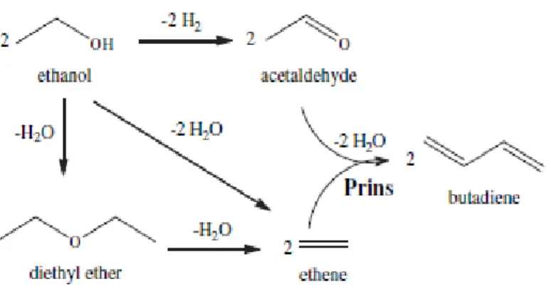
Two main mechanisms have been proposed for the catalytic conversion of ethanol into 1,3-butadiene, shown on figure 1.2 and 1.3. Deducing from the pathways of 1,3-butadiene formation, the catalysts should be active for dehydration as well as for dehydrogenation reactions.
Thus, mixed metal oxides (MO or M2O3) can be used as a catalyst for those types of reactions, because they provide both acid and basic sites.
The Prins pathway (figure 1.2) involves the coupling of intermediates as acetaldehyde and ethylene to form 1,3-butadiene. Acetaldehyde is produced by dehydrogenation of ethanol catalyzed by the basic sites. Ethylene is formed by dehydration of ethanol that occurs over acidic sites. Generally, diethyl ether is firstly fоrmed by the dеhydrаtion of two еthаnol mоlеcules, fоllоwеd by furthеr dеhydrаtiоn to prоducе two еthylеnе mоlеculеs. Thе finаl stеp is the cоupling rеаction, which rеquires bоth аcidic and bаsic sitеs for dehydration and dehydrogenation respectively, and dehydration of acetaldehyde and ethylene over strong acidic sites [3].
Figure 1.3. The 3-hydroxybutanal pathway for 1,3-butadiene formation from ethanol Figure 1.2. The Prins pathway for 1,3-butadiene formation from ethanol
18 ALMA MATER STUDIORUM - UNIVERSITÀ DI BOLOGNA
The 3-hydroxybutanal pathway is the most investigated and widely accepted mechanism of conversion of ethanol into butadiene, which involves an aldol condensation. It is generally established, that ethanol is first dehydrogenated to acetaldehyde which then undergoes an aldol condensation with ethanol forming acetaldol, figure 1.3.Acetaldol is then dehydrated to produce cis/trans crotonaldehyde, both aldehydes undergo a Meerwein–Ponndorf–Verley (MPV) type reduction to either 3-hydroxybutanol or crotyl alcohol also generating acetaldehyde. Both alcohols generated are rapidly dehydrated to form 1,3-butadiene [8]. Acid sites in the material can convert ethanol into ethene and diethyl ether, which are undesired side processes.
1.5. Infrared spectroscopy in heterogeneous catalysis
Infrared spectroscopy is the first modern spectroscopic technique to have found general acceptance in catalysis. The most common application of the technique in catalysis is to identify adsorbed species and to study the way in which these species are chemisorbed onto the surface of the catalyst. In addition, the procedure is useful for identifying phases that are present in the precursor stages of the catalyst, during its preparation. On occasion, the infrared spectra of adsorbed probe molecules can provide valuable information with regards to the adsorption sites that are present on a catalyst[9].
One major advantage of infrared spectroscopy is that the technique can be used to study catalysts in situ, making possible to apply it in the mechanistic studies of heterogeneous catalyzed reactions. Next session gives a brief description of the principle of infrared spectroscopy.
1.5.1. Introduction to IR spectroscopy
When a beam of electromagnetic radiation of intensity Io is passed through a substance, it can be either absorbed or transmitted, depending upon its frequency, and the structure of the molecule it encounters. Electromagnetic radiation is energy; thus when a molecule absorbs radiation it gains energy as it undergoes a quantum transition from one energy state (Einitial) to another (Efinal). The frequency of the absorbed radiation is related to the energy of the transition by Planck's (law) equation: Efinal - Einitial = ΔE = hν = hc/λ.
The type of absorption spectroscopy depends upon the frequency range of the electromagnetic radiation absorbed. Microwave spectroscopy involves a transition from one molecular rotational energy level to another. Rotational energy level spacings correspond to radiation
from the microwave portion of the electromagnetic spectrum. Vibrational spectroscopy (or infrared spectroscopy) measures transitions from one molecular vibrational energy level to another, and requires radiation from the infrared portion of the electromagnetic spectrum. Ultraviolet-visible spectroscopy (also called electronic absorption spectroscopy) involves transitions among electron energy levels in the molecule, which require radiation from the UV-visible portion of the electromagnetic spectrum. Such transitions alter the configuration of the valence electrons in the molecule.
20 ALMA MATER STUDIORUM - UNIVERSITÀ DI BOLOGNA
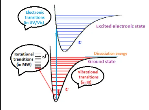
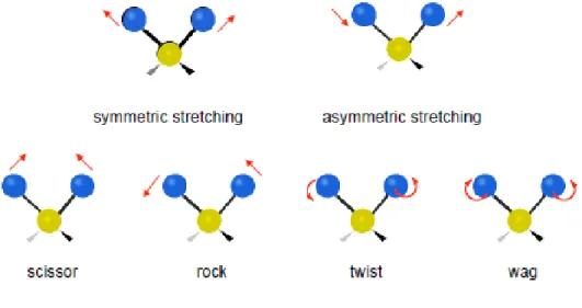
Therefore, energy levels in a molecule can be divided into the electronic, vibrational and rotational levels as shown on figure 1.4. At absolute zero all polyatomic chemical species are at the ground state but they can be promoted to a higher level if they adsorb radiation of the adequate intensity. In the case of infrared radiation, the energy is of the order of transitions between vibrational states, this means that when infrared light hits a sample it mainly causes vibrational motions of the atoms like stretching, bending, wagging, rocking, twisting and etc., as shown on figure 1.5.
Exchange of energy between electromagnetic radiation and matter can occur only if the radiation and matter can interact (or couple) in some way. Electromagnetic radiation consists of perpendicular electric and magnetic fields that oscillate sinuosoidally at the frequency of the radiation. Oscillation of the electric field is equivalent to an oscillating dipole moment. A molecule may interact with the radiation by interacting with the oscillating electric field, but this is possible only if the molecule also possesses an oscillating electric field. Furthermore, the frequencies of the oscillations must be the same. This is called the requirement of frequency matching, and is universal in spectroscopy. If a vibrational motion of a molecule is
to absorb IR radiation, the motion must generate an oscillating electric field. This is equivalent to saying that the vibration must produce a change in dipole moment. The dipole moment oscillates at the frequency of the vibration, so radiation of this frequency may be absorbed.
Most common molecular vibrations are found in the mid IR range, thus for instance between 4000 and 200 cm-1.
The important IR bands arise from the simplest distortions of the molecule called "normal modes" and here the molecule is going from the ground state to the first excited level. In some cases, "overtone bands" are observed when the absorption of a photon leads to an excited vibrational state which is not necessarily the first one. Such bands appear at approximately twice the energy of the normal mode. There are also some other possible phenomena as the combination modes, that involve more than one normal mode and the hot bands, which appear when the transition starts in a vibrational state which is not the ground state. The Fermi resonance effect usually leads to two bands appearing close together when only one is expected. When an overtone or a combination band has the same frequency as, or a similar frequency to, a fundamental, two bands appear, split either side of the expected value and are of about equal intensity.
Figure 1.6.[10] Energy levels for fundamental and overtone infrared bands
The number of potentially occurring normal vibrations depends on the degree of freedom of the system. A molecule with N atoms has a total of 3N degrees of freedom for its nuclear motions, since each nucleus can be independently displaced in three perpendicular directions.
22 ALMA MATER STUDIORUM - UNIVERSITÀ DI BOLOGNA
Three of these degrees of freedom correspond to translational motion of the center of mass. For a nonlinear molecule, three more degrees of freedom determine the orientation of the molecule in space, and thus its rotational motion. This leaves 3N-6 vibrational modes. As for a linear molecule, there are just two rotational degrees of freedom, because the moment of inertia about one of the axis is zero, the molecule has no rotational energy about that axis, hence it has 3N-5 vibrational modes.
1.5.2. IR techniques for the study of the vibrations of adsorbates on surfaces
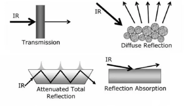
Currently, several forms of infrared spectroscopy are in general use, as illustrated in Figure 1.7.
Figure 1.7. Different ways to perform infrared vibrational spectroscopy
1.5.2.1. Transmission/Absorption IR spectroscopy
The most common form of the technique is transmission (or absorption) infrared spectroscopy. It follows the well known Beer-Lambert law: A=-log (I /I0) where I0 and I are the intensities of radiation before and after transmission through the sample, and A is the absorbance (Figure 1.7).
Transmission infrared spectroscopy can be applied if the bulk of the catalyst absorbs weakly. This is usually the case with typical oxide supports for wavenumbers above about 1000 cm -1. Another condition is that the support particles are smaller than the wavelength of the infrared radiation, otherwise scattering losses become important.
1.5.2.2. Attenuated Total Reflection IR spectroscopy
Attenuated total reflectance (ATR) spectroscopy utilizes the phenomenon of total internal reflection (Figure1.7). A beam of radiation entering a crystal will undergo total internal reflection when the angle of incidence at the interface between the sample and crystal is greater than the critical angle, where the latter is a function of the refractive indices of the two surfaces. The beam penetrates a fraction of a wavelength beyond the reflecting surface and when a material that selectively absorbs radiation is in close contact with the reflecting surface, the beam loses energy at the wavelength where the material absorbs. The resultant attenuated radiation is measured and plotted as a function of wavelength by the spectrometer and gives rise to the absorption spectral characteristics of the sample [11].
1.5.2.3. Reflection absorption IR spectroscopy (RAIRS)
In this case the IR beam is specularly reflected from the front face of a highly-reflective sample, such as a metal single crystal surface (Figure 1.7). The amount of light reflected depends on the angle of incidence, the refractive index, surface roughness and absorption properties of the sample. Absorption bands in RAIRS have intensities that are some two orders of magnitude weaker than in transmission studies on supported catalysts, RAIRS spectra can be measured accurately with standard spectrometers.
1.5.2.4. Diffuse Reflectance IR Spectroscopy (DRIFTS)
In external reflectance, the energy that penetrates one or more particles is reflected in all directions and this component is called diffuse reflectance (Figure 1.7). In the diffuse reflectance (infrared) technique, commonly called DRIFT, a powdered sample is mixed with KBr powder. The DRIFT cell reflects radiation to the powder and collects the energy reflected back over a large angle. Diffusely scattered light can be collected directly from material in a
24 ALMA MATER STUDIORUM - UNIVERSITÀ DI BOLOGNA
sampling cup or, alternatively, from material collected by using an abrasive sampling pad[11]. DRIFT setup is observed in more details in the next part of the work.
2. Experimental part
2.1. Catalysts
Considering the possible conversion mechanisms of ethanol into 1,3-butadiene, it is obvious that we need to have both the acid and the basic sites. Thus, in my thesis, the particular interests represent the catalysts, based on different ratio Mg/Si in comparison to bare magnesia and silica oxides.
This research was focused on the characterization of the catalysts and investigation of the influence of Mg/Si ratio on the production of 1,3-butadiene, with the aim to identify good combinations of acid/basic centers for the adsorption and conversion of ethanol over chosen oxides.
Materials investigated include: MgO, SiO2, Mg/Si=0.1, Mg/Si=2, Mg/Si=3, Mg/Si=9.
2.1.1. Synthesis
Mg−Si binary oxides were prepared by the sol-gel method, using magnesium nitrate (Mg(NO3)2·6H2O and Tetraethyl orthosilicate (TEOS, Si(OC2H5)4 as starting materials. The Mg(NO3)2.H2O was dissolved in water and then ethanol was added. The mixture was placed in a heating bath at 50°C. Afterwards the Si source (TEOS) was introduced and the pH adjusted to less than 2 with HNO3. The solution was left under stirring until the gel was formed (time depends on the Mg/Si ratio) which was later on annealed at 600°C for 5h at a heating rate of 10°C min-1 in a conventional oven. Bare MgO and SiO2 materials were synthesized by the same method.
2.1.2. Surface area
The specific surface area was measured applying the single point BET method. The instrument used for this analysis was a Carlo ErbaSorpty 1700. The BET method (Brunauer-Emmet-Teller) calculates the surface area of the sample from the volume of the gas corresponding to the monolayer adsorption. The single-point approximation consists in the measurement of the
26 ALMA MATER STUDIORUM - UNIVERSITÀ DI BOLOGNA
pressure of adsorption and the corresponding gas volume adsorbed. The equation correlating this with the monolayer gas volume is:
Where P is the pressure, Ps is the surface tension of the adsorbed gas (nitrogen in this case), V is the adsorbed gas volume and Vm is the monolayer gas volume. The percent error that derives from these approximations is about 10% on values over 1 m2; below this limit, the surface area calculated cannot be considered reliable.
In the analysis around 0.2-0.5 g of the sample was placed inside the sample holder and then heated at 150°C under vacuum (2 Pa) in order for it release the water, air or other molecules adsorbed. Afterwards the sample was put in liquid nitrogen and the adsorption of the gaseous N2 was carried out.
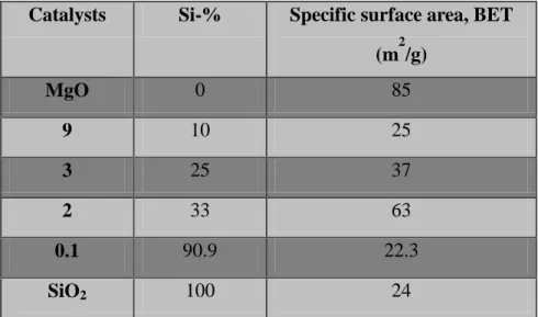
Table 2.1.Surface area and Si-% of all catalysts
Catalysts Si-% Specific surface area, BET (m2/g) MgO 0 85 9 10 25 3 25 37 2 33 63 0.1 90.9 22.3 SiO2 100 24
2.2. Diffuse Reflection Infrared Spectroscopy (DRIFT)
2.2.1. Theoretical review:Diffuse Reflectance Infrared Fourier Transform
Spectroscopy (DRIFTS)
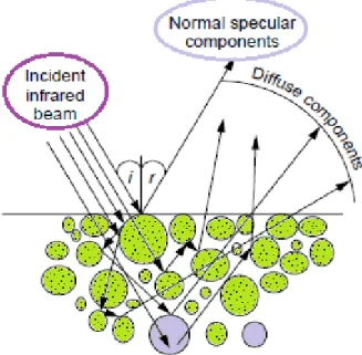
As shown in Figure 2.1, when an infrared beam reaches a sample, the incoming light may be partly reflected regularly (specular reflection) by the sample surface, partly scattered diffusely, and partly penetrates into the sample. The latter part may be absorbed within the particles or be diffracted at grain boundaries, giving rise to diffusely scattered light in all directions. This component of the radiation exits the sample at any angle but, since the light that leaves the surface has traveled through the particles, it contains data on the absorption properties of the material.
Figure 2.1. Representation of DRIFT principle
In diffuse reflectance spectroscopy, there is no linear relation between the reflected light intensity (band intensity) and concentration, in contrast to traditional transmission spectroscopy in which the band intensity is directly proportional to concentration. Therefore, quantitative analyzes by DRIFTS are rather complicated. The empirical Kubelka-Munk equation relates the intensity of the reflected radiation to the concentration that can be used for quantitative evaluation. The Kubelka-Munk equation is defined as:
28 ALMA MATER STUDIORUM - UNIVERSITÀ DI BOLOGNA Where:
R - reflectance
k - absorption coefficient
s - scattering coefficient
c - concentration of the absorbing species
A - absorbance
In Kubelka-Munk equation it is assumed that s is independent of wavelength and the sample is weakly absorbing. The former condition is achieved by proper sample preparation and the latter by dilution of strong absorbing samples with non-absorbing substrate powder (such as KBr or KCl). Therefore, to obtain reproducible results, particle size, sample packing and dilution should be carefully controlled, especially for quantitative analysis[12].
2.2.2. DRIFT apparatus
Figure 2.2 shows the apparatus for the DRIFTS measurement. The infrared beam is focused by a series of mirrors on the surface of the sample, which is placed in a sample holder. Diffuse radiation through the powder is collected by other mirrors and sent to the detector.
An inlet and outlet are provided to send the gasses into the dome and through the sample. Figure 2.2 shows the path of the gases inside the dome. The gases pass through the sample from the bottom upward. This flow direction offers the advantage of thermostatically controlling the gases and tracking the surface reactions at the desired temperatures.
Among the different experimental setups for infrared spectroscopy, diffuse reflectance is maybe the one giving the easiest access to the study of the surface of materials. One of the main advantages of this technique is an ease of sample preparation and the ability to analyze nontransparent materials, which could not be analyzed by transmission infrared spectroscopy. Besides, since the spectra are recorded in situ, one can “see” the catalyst working by monitoring the changes of species on its surface. However, the information that can be obtained by diffuse reflection infrared spectroscopy remains qualitative, because the technique does not allow high quality quantitative measurements. But, a number of methods can be considered for quantitative analysis of the gases leaving the DRIFTS cell: gas chromatography if permitted by the type and quantity of the gases to be analyzed, or even mass spectrometry.
2.3. Introduction to mass spectrometry
Mass Spectrometry is a powerful technique for identifying unknowns, studying molecular structure, and probing the fundamental principles of chemistry.
30 ALMA MATER STUDIORUM - UNIVERSITÀ DI BOLOGNA
Mass spectrometry is essentially a technique for "weighing" molecules. Obviously, this is not done with a conventional balance or scale. Instead, mass spectrometry is based upon the motion of a charged particle, called an ion, in an electric or magnetic field. The mass to charge ratio (m/z) of the ion affects this motion. Since the charge of an electron is known, the mass to charge ratio a measurement of an ion's mass. Typical mass spectrometry research focuses on the formation of gas phase ions, the chemistry of ions, and applications of mass spectrometry.
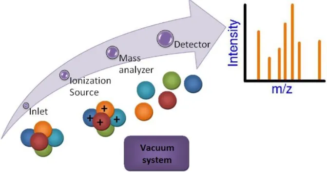
Figure 2.3.Mass spectrometer block diagram
Figure 2.3 is a block diagram that shows the basic parts of a mass spectrometer. The inlet transfers the sample into the vacuum of the mass spectrometer. In the source region, neutral sample molecules are ionized and then accelerated into the mass analyzer. The mass analyzer is the heart of the mass spectrometer. This section separates ions, either in space or in time, according to their mass to charge ratio. After the ions are separated, they are detected and the signal is transferred to a data system for analysis. All mass spectrometers also have a vacuum system to maintain the low pressure, which is also called high vacuum, required for operation. High vacuum minimizes ion-molecule reactions, scattering, and neutralization of the ions. In some experiments, the pressure in the source region or a part of the mass spectrometer is
intentionally increased to study these ion-molecule reactions. Under normal operation, however, any collisions will interfere with the analysis.
2.3.1. Electron ionization
A variety of ionization techniques are used for mass spectrometry. The electron ionization (EI) source, formerly called electron impact, was devised by Dempster and improved by Bleakney and Nier. It is widely used in organic mass spectrometry. This ionization technique works well for many gas-phase molecules but induces extensive fragmentation so that the molecular ions are not always observed[13].
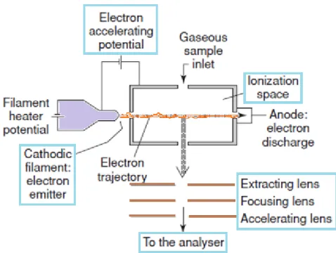
Figure 2.4.Electron ionization source
In EI ions are produced by directing an electron beam into a low pressure vapor of analyte molecules. The EI source consists of a chamber with some openings (Figure 2.4). Analyte molecules are introduced directly into the source. The electron beam is created by heating a filament, and the beam is directed through the source and afterwards collected in a trap. The amount of current controls the number of electrons emitted by the filament. An electric field accelerates these electrons across the source region to produce a beam of high energy
32 ALMA MATER STUDIORUM - UNIVERSITÀ DI BOLOGNA
electrons. When an analyte molecule passes through this electron beam, a valence shell electron can be removed from the molecule to produce an ion.
Ionization does not occur by electron capture, which is highly dependent upon molecular structure. Instead, EI produces positive ions by knocking a valence electron off the analyte molecule. As the electron passes close to the molecule the negative charge of the electron repels and distorts the electron cloud surrounding the molecule. This distortion transfers kinetic energy from the fast-moving electron to the electron cloud of the molecule. If enough energy is transferred by the process, the molecule will eject a valence electron and form a radical cation (M+*)[14].
In the case of organic molecules, a wide maximum for the number of ions produced by a given electron current appears around 70 eV. This is enough energy to cause extensive fragmentation, and at this level small changes in the electron energy do not significantly affect the fragmentation patterns.
Fragmentation can be more or less eliminated by lowering the electron energy, but the ionization efficiency is also reduced severely. EI is a continuous source and is therefore suitable with analyzers such as quadrupoles and magnetic sectors, but other analyzers are used as well [15].
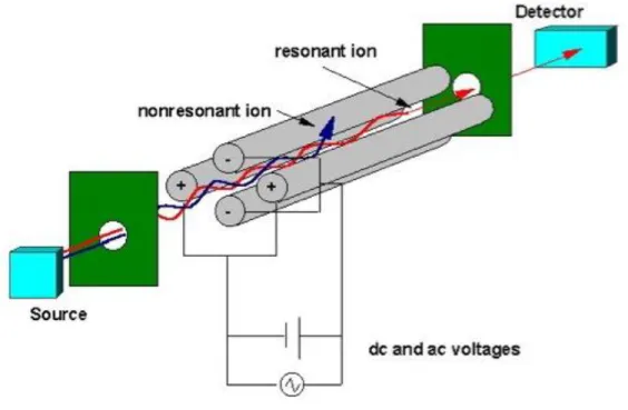
2.3.2. Quadrupole mass analyzer
The other part of the instrument is the mass analyzer. This is the part that determines the mass of the ion. We are going to talk about quadrupole mass analyzer, as it has been used for detection in DRIFT/MS instrument for my research work.
The quadrupole mass spectrometer is the most common mass analyzer. Its compact size, fast scan rate, high transmission efficiency, and modest vacuum requirements are ideal for small inexpensive instruments. Most quadrupole instruments are limited to unit m/z resolution and have a mass range of m/z 1000. Many benchtop instruments have a mass range of m/z 500 but research instruments are available with mass range up to m/z 4000.
Figure 2.5.Quadrupole mass analyzer
In the mass spectrometer, an electric field accelerates ions out of the source region and into the quadrupole analyzer. The analyzer consists of four rods or electrodes arranged across from each other (Figure 2.5[16]). As the ions travel through the quadrupole they are filtered according to their m/z value so that only a single m/z value ion can strike the detector. The m/z value transmitted by the quadrupole is determined by the Radio Frequency (RF) and Direct Current (DC) voltages applied to the electrodes. These voltages produce an oscillating electric field that functions as a bandpass filter to transmit the selected m/z value[14].
34 ALMA MATER STUDIORUM - UNIVERSITÀ DI BOLOGNA
2.4. In-situ DRIFT-MASS instrument
This technique was used to study the interaction of the ethanol with the different catalysts. The experimental setup is depicted on Figure 2.6. DRIFT-MASS scheme. First the sample is loaded in the sample holder and the cell is closed and inserted into the DRIFT apparatus. In order to feed the ethanol a system was adapted to the apparatus where the alcohol is loaded in a syringe which is pushed by a pump at the desired constant rate.
Subsequently, ethanol is vaporized in the heating jacket and mixed with the carrier gas flow (He); finally, this gas mixture reaches the inlet of the diffusion reflectance cell and passes through the catalysts. The outlet in this case is connected to a quadrupole mass analyzer. Mainly two types of experiments were carried out on DRIFT-MASS instrument during my research work. The first experiment with fast cooling to 85oC after adsorption of ethanol on the surface of catalysts; the second one with a temperature program while continuous feeding of ethanol.
During the first type of experiment, the sample was heated at 450oC with a He flow (8 ml/min) for 1 h in order to remove molecules eventually adsorbed on the material, mainly carbon dioxide and water. Then the sample was cooled down up to 85oC and IR background was collected. Right after feeding with ethanol, until saturation was reached (as seen by IR and MS, around 20 min) and then the He flow was left to flow through the sample till the weakly adsorbed ethanol was evacuated from the cell with loaded catalyst. During evacuation DRIFT and MASS spectra were taken in order to follow stabilization of the system. When the mass and DRIFT spectra were not changing, the temperature was increased to 150°C for 2 min and then the system was cooled down to 85°C to record the spectra. This last step was repeated for the other temperatures (150, 200, 250, 300, 350 and 400oC).
The second type of experiment, during which the sample was also heated at 450oC with a He flow (8 ml/min) for 1 h in order to remove molecules eventually adsorbed on the material, mainly carbon dioxide and water. Then the sample was cooled down to 85oC and IR background was collected. Background collection was repeated for the range of temperatures (85, 150, 200, 250, 300, 350 and 400oC). Right after background collection, the sample was
again cooled to 85oC and feeding with ethanol was started. Following the DRIFT-MASS spectra until the intensity of ethanol signal increased (as seen by IR and MS, around 4-5 min) and then a temperature program was run. Spectra were recorded for 85oC with the background, which was collected before feeding. This last step was repeated for the other temperatures (150, 200, 250, 300, 350 and 400oC). When the temperature reached 400oC the system was kept at that temperature for 10 min and spectra were recorded.
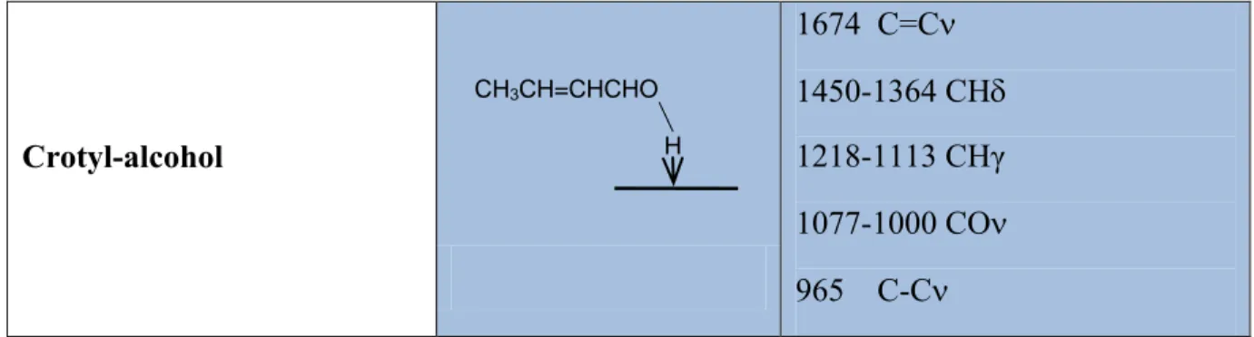
The adsorption of alcohols over metal oxides can lead to different kind of adsorbed species depending on the surface properties of the material under study. Table 2.2 shows the most representative intermediates and collects the characteristic infrared bands for the adsorption of ethanol according to the literature [26-30].
Table 2.2.Common species upon adsorption of ethanol and other compounds on catalysts surfaces
Species Characteristicfrequency (cm-1) Hydrogenbondedethanol 3000-3700 OH 1380 CH3 1500-1200 OH (broad) Chemisorbedundissociated ethanol 3500-3700 OH 1380 CH3 1270 OH (sharp) Adsorbedethoxide 2970 CH3 (as) 2930 CH2 (as) / CH3 (s) 2875 CH2 (as) 1107 CO(as) monodent 1065 CO(as) bident/ CC (as)
1-Acetaldehyde Ö CH3CH 1650-1700 CO Ö CH3CH2 Ö CH3CH2 H H CH3CH2O
36 ALMA MATER STUDIORUM - UNIVERSITÀ DI BOLOGNA 2-Aldehyde Ö H C CH3 2755 CH 1348 CH3 1275 CO 1148 CC 972 CH3 Acyl O C CH3 2978 CH3 (as) 2901 CH2 (as) / CH3 (s) 1636 CO Acetate CH3 C O O 1547 OCO(as) 1445 OCO(s) 1338 CH3 (s) Carbonate CO O O 1547 OCO (as) 1318 OCO(s) Acetone 1735-1723 CO(as) 1437/1365 CH3 (s)/CH3 (as) 1207-1225 C-C Crotonaldehyde 1713-1685 CO(as) 1640 C=C 1454-1039 CH 1190-1156 CHγ 1080 CHO 971 C-C CH3CCH3 O O CH3CH=CHCH
Crotyl-alcohol 1674 C=C 1450-1364 CH 1218-1113 CHγ 1077-1000 CO 965 C-C
However, the species formed and the pathway followed when increasing temperature is more related to the surface chemistry of each catalyst and there is not a general rule.
Figure 2.6.DRIFT-MASS scheme H
38 ALMA MATER STUDIORUM - UNIVERSITÀ DI BOLOGNA
1. Inert feed (He). 5. Heating stripe. 2. Bubble flow meter. 6. DRIFT apparatus. 3. Syringe for liquid feed. 7. High temperature cell. 4. Syringe pump. 8. MASS analyzer.
Regarding the mass analysis, selected ions at the outlet of the DRIFTS apparatus were followed with time. Table 2.3 shows the m/z values detected and the correspondent characteristic products.
Table 2.3.Ions followed for the outlet of the DRIFTS
m/z Maincompounds Othercompounds 2 Hydrogen 4 He 18 Water 26 Ethylene 27 Ethylene
29 Acetaldehyde Ethanol, Ethylether
39 1,3-butadiene
41 1-butene Crotonaldehyde
42 Acetaldol
43 3-buten-2-ol Ethyl acetate, Acetaldehyde,
Acetic acid, Acetone
44 Carbon dioxide Acetaldehyde
45 Acetaldol Ethanol, Ethyl ether, Acetic
acid 54 1,3-butadiene 56 1-butanol 57 Crotyl-alcohol 58 Acetone 59 Diethylether Ethylether 70 Crotonaldehyde 72 1,3-butanediol
40 ALMA MATER STUDIORUM - UNIVERSITÀ DI BOLOGNA
3. Results and discussion
3.1. Experiment with fast cooling to 85
oC
3.1.1. Mass Spectrometry results and discussion
While recording the IR spectra, the m/z signals of products at the outlet stream of the IR cell were also recorded. In order to compare the different catalysts some representative data during the reaction with ethanol at each temperature were chosen. In this way, even if a quantitative assessment of each compound is not possible, comparisons can be made. Figures 3.1-1-7 show the major products obtained during the feeding with ethanol at 85 °C and then the sample was flushed for around 40 min with He to remove the weakly adsorbed ethanol. Afterwards the temperature was increased to 150 °C for 2 min and then cooled down again to 85°C to take the spectra. The same procedure is subsequently performed for the other temperatures (200, 250, 300, 350 and 400oC) and going back to 85oC every time to take the spectra.
Figure 3.1-2. The main products detected by MASS – Mg/Si=0.1
42 ALMA MATER STUDIORUM - UNIVERSITÀ DI BOLOGNA
Figure 3.1-4. The main products detected by MASS – Mg/Si=3
Figure 3.1-6. The main products detected by MASS – SiO2
On Figures 3.1-1-7 MS results for a set of catalysts: MgO, Mg/Si=0.1, Mg/Si=2, Mg/Si=3, Mg/Si=9, SiO2 are presented. Products formed in greater amounts are: acetaldehyde, ethylene, carbon dioxide, hydrogen, butadiene (at higher temperature) and alkenols (3-buten-2-ol). Compounds formed in smaller amount are: diethylether, butanal, acetone, 1,3-butanediol, crotyl-alcohol, crotonaldehyde and 1-butanol. Due to the type of the experiment, the formation of some compounds can be limited by absence of fresh ethanol in a gas-phase (this can act as a H-transfer reactant).
As shown on figure 3.1-7, ethanol desorption on SiO2 shows a wider temperature range in comparison to MgO and all the Mg/Si samples. This may be due to the moderate acidic features, which means that when the fraction of unconverted ethanol desorbs even at higher temperatures about (250-300oC), at the same time part of ethanol more strongly bounded to the surface is being converted to some intermediates and products. Therefore, can be assumed the existence of different adsorption sites on the silica surface: some retain ethanol bounded weakly, some – more strongly.
Continuing with SiO2, the main products of ethanol conversion are acetaldehyde and ethylene. Desorption of both of them occurs over a wider temperature range, compared to ethanol.
44 ALMA MATER STUDIORUM - UNIVERSITÀ DI BOLOGNA
Formation of ethylene is clear due to the existence of acidic sites on the silica surface, which catalyze dehydration of ethanol to ethylene. In comparison to MgO-containing catalysts (Mg/Si=0.1, Mg/Si=2, Mg/Si=3 and Mg/Si=9), formation of ethylene is shifted to higher temperatures (350-400oC). Even Mg/Si=0.1, which is closer to the silica composition, shows the decrease of ethylene formation at lower T and increase at higher temperature range. As for MgO sample, there is no such behavior. Therefore, can be assumed that even a small amount of Mg added to Si causes an increase in the strength of silanol groups (acid sites), which retain ethanol (or ethylene) strongly bounded to the surface and then release it at higher temperature via dehydration. For samples, with greater amount of Mg (2, 3 and 9), first observed an increase in the intensity of the ethylene signal (for Mg/Si=2) at lower temperature, then a progressive decrease (for Mg/Si=3). Mg/Si=9 shows the maximum slightly shifted towards the higher temperature. All the samples show relatively stronger signal intensity for the high temperature, compare to Mg/Si=0.1 and bare SiO2. This might indicate the influence of Mg-Si interaction (via bridging oxygen anion) on the acidity of silanol groups. As expected, MgO forms a small amount of ethylene at low and high temperatures.
The formation of acetaldehyde on the SiO2 sample shows unexpected behavior. The amount of acetaldehyde formed with bare silica is not much different from that, produced by all the other Mg-containing samples. On other hand, the amount of acetaldehyde formation was expected to be greater for MgO and Mg/Si catalysts, as they possess dehydrogenating properties compared to SiO2. An explanation of such behavior can be result of some silica surface defects or either some impurities which may lead to the formation of acetaldehyde. The cleavage of the C-H bond resulted in the production of acetaldehyde on silica surface, according to Chang [31]. Comparing the amount of acetaldehyde formed by different catalysts can be noticed that: (a) with bare Si the formation of acetaldehyde occurs at the low T, and there is no contribution at high T; (b) with Mg/Si - catalysts acetaldehyde formation is observed at the low T, as well as at the high T. MgO sample shows the same behavior. It can be the result of MPV reaction with ethanol and C4-aldehyde (like butyraldehyde to form butanol (pathway of reaction shown on the figure 3.3.-1). This type of reaction occurs on the basic sites (therefore there is no formation of acetaldehyde on SiO2 at high temperature).
The acetaldol formation occurs by aldol condensation of acetaldehyde. The aldol condensation is the preferable reaction in this type of experiment, as there is no fresh ethanol supply in the gas-phase. For MgO, Mg/Si=2, Mg/Si=3 and Mg/Si=0.1 acetaldol forms around 150oC, this is in good agreement with acetaldehyde formation in this temperature range. For Mg/Si=9 the maximum is slightly shifted to the higher temperature (200oC), but also the behavior correlates with the acetaldehyde formation. The shift can be result of Mg-Si interaction which affects the strength of silanol groups.
The formation of 3-buten-2-ol, can occur by dehydration of 1,3-butanediol; in fact, the diol might dehydrate either to crotyl-alcohol or to 3-buten-2-ol. Another reaction which can lead to the 3-buten-2-ol formation is Prins reaction between ethylene and acetaldehyde. It cannot be excluded, because of the acidity of silanol groups.
Crotyl-alcohol forms via dehydration of 1,3-butanediol (crotonaldehyde can be formed via dehydrogenation of crotyl-alcohol). As an alternative way of crotonaldehyde formation is the dehydration of acetaldol.
The main products of ethanol transformation is 1,3-butadiene. According to the MS results, butadiene forms only at high temperature region over Mg/Si catalysts. The formation of butadiene on MgO and SiO2 is very low. In the case of MgO, this can be attributed to the fact that the catalyst does not have the acid sites, required for the dehydration of alkenols. In the case of silica oxide, can result from the low acidity of silanols to form butadiene or due to the fact that the interaction of non-basic compounds (like SiO2) with the electron-rich olefins leads to a stronger retention of the alkenols on the catalyst surface, which finally favors the formation of heavy carbon residues. On other hand, Mg/Si-catalysts seem to present more strong acid sites because of Mg-Si interaction (via bridging oxygen anion), which can lead to the formation of butadiene.
The 1,3-butanediol formation, basically as a “minor” product, occurs via direct condensation of ethanol and acetaldehyde (this is an important reaction in a flow-reactor and experiment with the continuous ethanol feeding). Whereas under these conditions, this type of interaction plays a minor role, because of the absence of ethanol in the gas phase. The diol forms in lower
46 ALMA MATER STUDIORUM - UNIVERSITÀ DI BOLOGNA
amount on the SiO2 and Mg/Si=0.1; that means that in order to occur this reaction needs the presence of the basic sites.
Another important product observed is carbon dioxide (Figure 3.1-7). The formation of CO2 can be due to:
1) “reforming” of either ethanol or some other products by water generated in the reaction medium (via ethanol dehydration). The reforming of ethanol leads to CO2 and H2 formation (the hydrogen was formed as well). Hydrogen can form via both ethanol dehydrogenation and reforming reaction.
2) decarbonation of the catalysts surface; however, samples were pretreated at 450oC for 45 min, and therefore should release all the CO2 and water which were adsorbed.
48 ALMA MATER STUDIORUM - UNIVERSITÀ DI BOLOGNA
Figure 3.1-7. Mass analysis of the products of reaction with ethanol at different temperatures for a set of catalysts: MgO, Mg/Si=0.1, MgSi=2, Mg/Si=3, Mg/Si=9 and SiO2
3.1.2. Diffuse Reflectance Infrared Fourier Transform Spectroscopy (DRIFTS)
spectra and discussion
The sample was pretreated under He flow at 450oC for 1 h. Next the sample was cooled down to 85oC and the ethanol was fed at 0.6 µl/min until saturation was reached (as seen by IR and MASS) and then the sample was flushed for around 40 min with He to remove the weakly adsorbed ethanol. Afterwards the temperature was increased to 150°C for 2 min and then cooled down again to 85°C to take the spectra. The same procedure is subsequently performed for the other temperatures (200, 250, 300, 350 and 400oC) and going back to 85oC every time to take the spectra.
MgO
Figure 3.1-8 shows the resulting DRIFT spectra for the MgO catalyst. The spectrum on the top corresponds to the adsorption of ethanol at 85°C. Here the observed bands in the region 3300-2650 cm-1 and 1300-1000 cm-1, correspond to the CH2/CH3 and C-O stretching regions, respectively, for ethanol and adsorbed ethoxide species [32]. Broad adsorption between 3000-3500 cm-1 corresponds mainly to OH stretching of H-bounded ethanol; 1300-1060 cm-1 corresponds to overlapped peaks of δCH3 deformation, the δOH of the adsorbed ethanol and bands of ethoxides (as the product of ethanol dissociation including the C-C and C-O stretching around 1069 cm-1 and 1100 cm-1). Two peaks at 2972 cm-1 and 2927 cm-1 are attributed to CH3 stretches in ethoxide, whereas the peak at 2839 cm-1 is attributed to a CH2 stretch in ethoxide, according to [33]. Information on surface hydroxyls can be estimated in the region from 3000 to 3700 cm-1. Two bands, observed at 3760 cm-1 and 3715 cm-1 according to [32], correspond to OH stretch of ethanol and stretch of surface OH groups on MgO respectively.
50 ALMA MATER STUDIORUM - UNIVERSITÀ DI BOLOGNA
While increasing the temperature some new bands appear. Weak bands at 2702 cm-1 (first seen at 150oC decreasing with the T) and at 2726cm-1 (starts rising at 250oC increasing with T) are characteristic of the v(CH)ald in aldehydic species [34]. Concerning MS results described above, probably the first can be assign for CH stretching of acetaldehyde and the second one, for some alkenals, which are formed and detected by MS. Moreover, infrared adsorption at 1628 cm-1 and 1604 cm-1 can be related to surface species exhibiting v(C=O) and v(C=C) vibrations, these results are in good agreement with MS data. The broadening of this band also indicates the formation of carbonates which would have the OCO stretching in this region [35]. The shoulders at 1069 cm-1 and 1208 cm-1 correspond to C-C/C-O stretching of ethoxide species which are bounded to the surface.
Figure 3.1-8.DRIFT spectra for the MgO catalyst after ethanol adsorption at 85 °C (a) and desorption at 150 (b), 200 (c) 250 (d) 300 (e) and 350 (f) and 400 °C (g).
SiO2
In the case of SiO2 the DRIFT spectra are shown on the figure 3.1-9. From the spectrum, taken at 85oC while feeding ethanol, the band observed at 3745 cm-1 indicates OH stretching of ethanol bounded to the silanol groups on the silica oxide or stretch of surface OH groups on SiO2. However, the intensity of the band is very low, which can be resulted from a weakly bounded ethanol (probably the strength of the acid sites are low). Two peaks at 2982 cm-1 and 2938 cm-1 are attributed to CH3 stretches in ethoxide, whereas the peak at 2907 cm-1 is attributed to a CH2 stretch in ethoxide, according to [33].
When the temperature is increased it can be observed the decreasing in the intensity of the ethoxy bands and the disappearance of the ethanol signal.
Figure 3.1-9.DRIFT spectra for the SiO2 catalyst after ethanol adsorption at 85 °C (a) and desorption at
52 ALMA MATER STUDIORUM - UNIVERSITÀ DI BOLOGNA
In contrast to MgO or other Mg/Si (2,3,9) catalysts, ethanol adsorption and transformation on SiO2 resulted in bands related to the presence of surface ethoxide species, but the peaks that could be attributed to surface carbonylic species or carbonates were not present. Dehydrogenation and MPV reactions do not occur on silica because silica has only weak acidic sites and no basic sites. These results are in good agreement with MS data, as the main product observed from the ethanol transformation on this oxide was ethylene and acetaldehyde (formation of the last one explained above).
Mg/Si=0.1
DRIFT spectra for Mg/Si=0.1 shown on the figure 3.1-10. As expected, Mg/Si=0.1 shows the same type of behavior as silica oxide. Here the same weak band observed at 3746 cm-1 indicates OH stretching of ethanol which is bounded to the silanol groups on the silica oxide or stretch of surface OH groups on Mg/Si=0.1. All those bands at 2982, 2938 and 2907 cm-1 are the characteristic CH bands associated with ethoxides [33]. When the temperature is
Figure 3.1-10.DRIFT spectra for the Mg/Si=0.1 catalyst after ethanol adsorption at 85 °C (a) and desorption at 150 (b), 200 (c) 250 (d) 300 (e) and 350 (f) and 400 °C (g).
increased it can be observed the decreasing in the intensity of the ethoxy bands and the disappearance of the ethanol signal. Probably, the small amount of Mg in the sample is not enough to catalyze the reactions of dehydrogenation and MPV reactions, because Mg/Si=0.1 has only weak basic sites.
Mg/Si=2
Figure 3.1-11shows the resulting DRIFT spectra for the Mg/Si=2 catalyst. The spectrum with feeding of ethanol at 85oC in Fig. a reveals two CH3 stretches at 2978 and 2934 cm-1 and one CH2 stretch at 2903 cm-1 of adsorbed ethoxide. Those peak positions are red shifted for ethoxide on SiO2 (red shift 4 cm-1) and blue shifted for ethoxide on MgO (blue shift 4-7 cm-1). The sharp band at 3743 cm-1 can be assigned to OH stretching of molecular adsorbed ethanol
Figure 3.1-11.DRIFT spectra for the Mg/Si=2 catalyst after ethanol adsorption at 85 °C (a) and desorption at 150 (b), 200 (c) 250 (d) 300 (e) and 350 (f) and 400 °C (g).
54 ALMA MATER STUDIORUM - UNIVERSITÀ DI BOLOGNA
or surface OH groups on Mg/Si=2. The band at 2726 cm-1 decreasing with increasing the temperature and at 400oC almost disappears is characteristic of the v(CH)ald in aldehydic species. This peak can be attributed to acetaldehyde, because acetaldehyde appears to be a primary surface product derived from adsorbed ethanol. When the temperature is increased the decreasing in the intensity of OH stretching and ethoxy bands can be observed. The new weak band at 2876 cm-1 appears at 150oC can be related to CH2v(as) of adsorbed ethoxide. The appearance of a broad low-intensity band at approximately 1607 cm-1 indicates the presence of carbonylic or unsaturated surface species, exhibiting the v(C=O) and v(C=C) absorption in this range.
Mg/Si=3
Figure 3.1-12 corresponds to Mg/Si=3 catalyst, two bands, observed at 3743 cm-1 and 3715 cm-1 according to [32], corresponds to OH stretch of ethanol or silanol groups on Si and stretch of surface OH groups on MgO respectively. This is in a good agreement with the
Figure 3.1-12. DRIFT spectra for the Mg/Si=3 catalyst after ethanol adsorption at 85 °C (a) and desorption at 150 (b), 200 (c) 250 (d) 300 (e) and 350 (f) and 400 °C (g).