POLITECNICO DI MILANO
School of Industrial and Information EngineeringMaster of Science in Telecommunications Engineering Electronic, Information and Bioengineering Department
Cell Discovery with Directive Antennas in mm-wave 5G Networks
Supervisor: prof. Antonio Capone
Assistant supervisors: prof. Ilario Filippini dr. Vincenzo Sciancalepore
Denny Tremolada ID 816925
A
BSTRACTThe growth of Internet traffic and the increasing relevance of network connections are driving network operators and researchers towards a new standard in mobile communications known as 5G. One of its features is related to the transition from the frequencies in UHF band to the exploitation of the so-called millimeter waves (mm-waves), between 30 and 300 GHz, with a particular attention to the 60 GHz bandwidth, which can offer significant performances in terms of capacity.
The use of these particular frequencies causes a radical change in the transmission mech-anisms, limiting their use to microcells with limited coverage. This implies the inability for a network based only on mm-waves to provide a reliable service and the need to maintain a legacy network composed of macrocells and based on lower frequencies. The MiWEBA project therefore proposes a functional split between C-plane and U-plane, respectively dedicated to the transmission of signaling messages by exploiting the macrocells and to high-capacity user transmissions using microcells.
One of the main drawbacks of the use of mm-waves is related to the impossibility to use omnidirectional antennas during cell discovery and the consequent need to exploit beamforming techniques to compensate for the lower coverage. In order to use proper antenna configurations, a localization mechanism allows the BS to obtain information about the positions of the MSs. The entire process can, however, be delayed by the use of unsuitable configurations, due to the inaccuracy of the localization service and the possible presence of obstacles in the propagation environment. The use of algorithms able to define an effective sequence of antenna configurations is thus at the basis of a satisfactory result in terms of time employed during the cell discovery, in addition to the possibility to apply the concept of learning memory and exploit information based on previous transmissions in order to further shorten the duration of the process.
In this thesis work we analyze the behavior of three algorithms in propagation environments characterized by different levels of MS location information accuracy and the possible presence of physical obstacles and the impact of learning memory on the cell discovery process.
S
OMMARIOL’aumento del traffico Internet e l’importanza sempre maggiore delle connessioni di rete stanno spingendo operatori e ricercatori verso la definizione di un nuovo standard nelle comunicazioni mobili noto come 5G. Una delle sue caratteristiche è legata al passaggio dalle frequenze nella banda UHF all’utilizzo delle cosiddette onde millimetriche (mm-waves), comprese tra 30 e 300 GHz, con una particolare attenzione alla banda a 60 GHz, in grado di offrire prestazioni notevoli in termini di capacità.
L’utilizzo di queste particolari frequenze comporta un cambiamento radicale nelle modalità di trasmissione, che ne limita l’uso a microcelle con copertura limitata. Ciò implica l’impossibilità da parte di una rete basata solo su mm-waves di fornire un servizio affidabile e la necessità di mantenere una rete legacy composta da macrocelle e basata su frequenze minori. Il progetto MiWEBA propone dunque una separazione funzionale tra C-plane e U-plane, dedicati rispettiva-mente alla trasmissione di messaggi di signaling sfruttando le macrocelle e a trasmissioni ad alta capacitá agli utenti utilizzando microcelle.
Uno dei principali svantaggi dell’utilizzo delle mm-waves è legato all’impossibilità di usare antenne omnidirezionali durante la cell discovery, e alla conseguente necessità di usare tecniche di beamforming per compensare la minor copertura. Al fine di utilizzare configurazioni di antenna appropriate, un meccanismo di localizzazione permette alla BS di ottenere informazioni sulle po-sizioni delle MS. L’intero processo può tuttavia essere ritardato dall’utilizzo di configurazioni non adatte, dovuto all’inaccuratezza del servizio di localizzazione e alla possibile presenza di ostacoli nell’ambiente di propagazione. L’utilizzo di algoritmi in grado di definire un’efficace sequenza di configurazioni di antenna è dunque alla base di un risultato soddisfacente in termini di tempo impiegato durante il processo, oltre alla possibilità di applicare il concetto di learning memory e sfruttare le informazioni basate sulle precedenti trasmissioni al fine di ridurne ulteriormente la durata.
In questo lavoro di tesi si analizzano il comportamento di tre algoritmi in ambienti di propagazione caratterizzati da diversi livelli di accuratezza dell’informazione di localizzazione delle MS e dall’eventuale presenza di ostacoli fisici e l’impatto della learning memory nel processo di cell discovery.
T
ABLE OFC
ONTENTS Abstract i Sommario iii Page List of Figures 1 List of Tables 3 1 Introduction 5 2 Introduction to 5G standard 7 2.1 5G overview . . . 7 2.2 5G main requirements . . . 9 2.3 5G application scenarios . . . 13 2.4 5G spectrum opportunities . . . 143 Mm-wave access networks 17 3.1 HetNet . . . 17
3.2 Mm-waves main features . . . 19
3.3 Directional transmissions . . . 24
3.4 Advanced network architectures . . . 25
3.4.1 Control and user plane separation . . . 25
3.4.2 C-RAN solutions . . . 26
3.4.3 Green networking solutions . . . 29
3.5 Initial cell discovery . . . 31
4 Algorithms and learning memory procedure 33 4.1 Directional cell discovery . . . 33
4.2 Random discovery algorithm . . . 35
4.3 DGS algorithm . . . 35
4.5 Learning memory mechanism . . . 37
4.6 Getting location information . . . 38
5 Numerical results 41 5.1 Propagation model and playground . . . 41
5.2 Obstacle-free scenario . . . 45
5.3 Perfect context information scenario . . . 52
5.4 Realistic scenario . . . 59
5.5 Realistic scenario with MS in the corner . . . 68
6 Conclusions and future developments 73 6.1 Conclusions . . . 73 6.2 Future developments . . . 74 A Appendix A 77 B Appendix B 79 C Appendix C 81 Bibliography 85
L
IST OFF
IGURES2.1 Differences between 4G and 5G technical objectives . . . 9
2.2 Comparison between rates in mobile communication generations . . . 9
2.3 Latency times comparison . . . 10
2.4 HetNet . . . 12
2.5 Modular Antenna Array architecture . . . 13
2.6 Main frequency bands for wireless communications between 2 and 90 GHz . . . 15
2.7 Spectra available around 60 GHz . . . 15
3.1 Signal attenuation at sea level and 20 °C versus log frequency . . . 20
3.2 Rainfall attenuation vs frequency . . . 21
3.3 Proposed architecture for 5G cellular networks . . . 26
3.4 C-RAN architecture model . . . 27
3.5 C-RAN centralized model . . . 28
3.6 Fully centralized and partial centralized architectures . . . 28
3.7 Components of the power consumption of China Mobile . . . 29
3.8 Mobile Network Load in Daytime . . . 30
3.9 Deafness problem . . . 31
3.10 Omnidirectional vs directional antennas coverage . . . 32
4.1 Discovery Greedy Search . . . 36
4.2 Enhanced Discovery Procedure . . . 37
4.3 WiFi fingerprinting-based localization service . . . 39
5.1 Obstacles and MSs location . . . 43
5.2 Comparison between DGS and EDP in a memoryless scenario . . . 45
5.3 Comparison between standard deviation values of the number of switches with DGS and EDP in a memoryless scenario . . . 47
5.4 Average number of switches for a BS-MS connection in an obstacle-free propagation scenario . . . 48
5.5 Comparison between the average number of switches using DGS and EDP without exploiting memory . . . 52
5.6 Reachability prevented by reflection mechanisms . . . 53 5.7 Average number of switches when learning memory is applied . . . 55 5.8 Configuration affected by memory range . . . 56 5.9 Comparison between algorithms in a memoryless 9-obstacle scenario with location
errors . . . 59 5.10 Comparison between DGS and EDP in a memoryless obstacle-free and in a memoryless
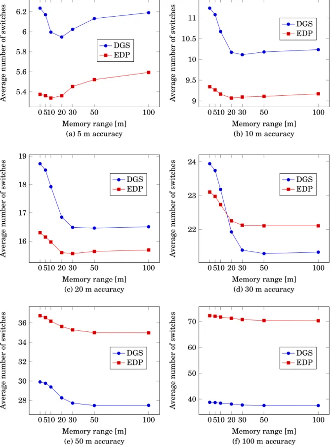
9-obstacle scenario with location errors . . . 60 5.11 Variation of the number of switches when different accuracy values are applied . . . . 63 5.12 Playground representation . . . 66 5.13 New playground representation . . . 68
L
IST OFT
ABLES2.1 Mobile subscription essentials . . . 8
2.2 Traffic essentials . . . 8
5.1 Saved switches for each memory access with DGS algorithm . . . 49
5.2 Saved switches for each memory access with EDP algorithm . . . 50
5.3 Percentage decrease by learning memory application using DGS algorithm . . . 50
5.4 Percentage decrease by learning memory application using EDP algorithm . . . 51
5.5 Saved switches for each successful memory access with DGS algorithm . . . 57
5.6 Saved switches for each successful memory access with EDP algorithm . . . 57
5.7 Average percentage decrease with DGS algorithm . . . 58
5.8 Average percentage decrease with EDP algorithm . . . 58
5.9 Percentage decrease using DGS algorithm . . . 64
5.10 Percentage decrease using EDP algorithm . . . 64
5.11 Percentage decrease using random algorithm . . . 64
5.12 Average percentage of successful accesses using DGS algorithm . . . 65
5.13 Average percentage of successful accesses using EDP algorithm . . . 65
5.14 Average percentage of successful accesses using random algorithm . . . 66
5.15 Memory content of a generic simulation . . . 67
5.16 Number of beams with narrow beamwidths . . . 67
5.17 Average number of switches with memoryless transmissions . . . 69
5.18 Percentage decrease given by memory in DGS algorithm . . . 69
5.19 Percentage decrease given by memory in EDP algorithm . . . 70
5.20 Percentage decrease given by memory in random algorithm . . . 70
5.21 Percentage of successful memory accesses with DGS algorithm . . . 70
5.22 Percentage of successful memory accesses with EDP algorithm . . . 71
5.23 Percentage of successful memory accesses with random algorithm . . . 71
A.1 DGS switches with memory . . . 77
A.2 EDP switches with memory . . . 77
A.3 Successful memory attempts with DGS algorithm . . . 78
A.5 Successful memory attempts with EDP algorithm . . . 78
A.6 Unsuccessful memory attempts with EDP algorithm . . . 78
B.1 DGS switches with memory . . . 79
B.2 EDP switches with memory . . . 79
B.3 Successful memory attempts with DGS algorithm . . . 79
B.4 Unsuccessful memory attempts with DGS algorithm . . . 80
B.5 Successful memory attempts with EDP algorithm . . . 80
B.6 Unsuccessful memory attempts with EDP algorithm . . . 80
C.1 Successful memory attempts with DGS algorithm . . . 81
C.2 Unsuccessful memory attempts with DGS algorithm . . . 81
C.3 Successful memory attempts with EDP algorithm . . . 81
C.4 Unsuccessful memory attempts with EDP algorithm . . . 82
C.5 Successful memory attempts with random algorithm . . . 82
C.6 Unsuccessful memory attempts with random algorithm . . . 82
C.7 Average amount of saved switches for every memory access with DGS algorithm . . . 82
C.8 Average amount of saved switches for every successful memory access with DGS algorithm . . . 82
C.9 Average amount of saved switches in each pattern with DGS algorithm . . . 82
C.10 Average amount of saved switches for every memory access with EDP algorithm . . . 83
C.11 Average amount of saved switches for every successful memory access with EDP algorithm . . . 83
C.12 Average amount of saved switches in each pattern with EDP algorithm . . . 83
C.13 Average amount of saved switches for each memory access with random algorithm . . 83
C.14 Average amount of saved switches for every successful memory access with random algorithm . . . 83
C
H A P T E R1
I
NTRODUCTIONThe evolution in the mobile communication field is going towards the definition of the 5G standard, which includes a larger set of applications in addition to the traditional services. The requirements of a subset of the use-cases can be fulfilled by an improvement of current mobile systems. Conversely, the larger relevance of high-rate and low-latency applications is leading towards the utilization of higher frequency transmissions. In particular, researchers and network operators are going beyond UHF frequencies and focusing on 60 GHz millimeter-waves (mm-waves) communications, able to guarantee remarkably better performances in terms of capacity as well as the possibility of an unlicensed exploitation of such frequency band.
However, mm-waves communications are heavily affected by higher path loss and obstacle attenuation, as well as a larger conditioning by the presence of physical elements in the propaga-tion environment. Moreover, propagapropaga-tions features limit their use to Line-Of-Sight (LOS) and low-order reflected transmissions, which imply a radical change of communication mechanisms. The drawback of the higher path loss can be compensated for by the application of beamforming techniques that focus the energy towards specific directions. The use of narrow beams helps to achieve suitable transmissions, as it allows covering typical propagation distances. However, these features obstruct the exclusive utilization of mm-waves, as they cannot provide a continuous coverage and their use is limited to short-range small cells.
In order to guarantee a reliable service, the maintenance of a legacy network, based on lower frequencies, is required, in particular related to the exchange of signaling messages. A multi-layer HetNet represent a valid solution, able to combine the better coverage of a macrocell with the higher capacity of small cells. In order to exploit the features of both cell typologies, the network architecture proposed in the MiWEBA project is based on a functional split between U-plane and C-plane. The signaling messages exchange will be managed by legacy communication network, able to guarantee a more reliable service as it is less affected by the propagation drawbacks of
mm-waves, which conversely are limited to data transmissions.
The utilization of small cells is based on a connection establishment between a User Equip-ment (UE) and a mm-wave BS. The features of beamforming techniques hinder the cell discovery procedure, as the utilization of narrow beams implies that both UE and BS are required to beam out each other in order to begin the synchronization procedures needed for the association phase. Consequently, the use of unsuitable beams can result in a remarkable delay, due to the large amount of available antenna configurations.
In this work, we analyze the behavior of three algorithms that define an antenna configuration sequence to be used for cell discovery. The cell search procedure is supported by an external localization service, which allows obtaining information about the MS position. Such information will be provided from the MS to the macro cell BS exploiting legacy communication network, with the aim of assisting the evaluation of a proper antenna configuration and reducing the time needed for the procedure. The performances of the algorithms are compared by using several propagation scenarios with different characteristics in terms of accuracy of the localization information and impact of possible obstacles in the environment. Moreover, we introduce the concept of learning memory procedure, able to exploit the information about previous connections in order to successfully assist the procedure and further reduce the delay.
This thesis work is organized as follows: Chapter 2 introduces the main characteristics and reasons that led to the definition of 5G standard. In Chapter 3 the significant aspects of the propagation with millimeter waves are highlighted, as well as a description of the most relevant architectural solutions that will characterize mm-wave access networks. Chapter 4 provides a detailed description of the algorithms used to define configuration sequences to be exploited during the cell search procedure, in addition to introducing the concept of learning memory. Chapter 5 focuses on the numerical results obtained from Matlab simulations, while eventually Chapter 6 contains the conclusions of this thesis work, as well as suggestions for future works on this topic.
C
H A P T E R2
I
NTRODUCTION TO5G
STANDARDThis first Chapter is dedicated to a general description of 5G standard: Chapter 2.1 deals with an introduction and the reasons behind 5G standardization. In Chapters 2.2 the main requirements of 5G networks are listed. Chapter 2.3 contains a description of the main service types, as well as an introduction to the concept of SDN and NFV. Eventually, Chapter 2.4 explains some significant reasons that led to the choice of mm-waves.
2.1
5G overview
In the last few years, high-speed mobile connectivity is becoming one of the main topics in telecommunication field. An Internet connection is now a basic requirement in common life and network providers have to fulfill this need, that will become increasingly important in the next years, when Internet will be related to a greater number of aspects. Technologies that today are at the dawn, as wearable devices, and others that are still being studied, such as self-driving cars, will represent an important aspect of life in a few years. Moreover, it cannot be overlooked the impact of the Internet of Things (IoT), enabling the possibility to connect to Internet a greater number of devices, in addition to the objective of the creation of smart cities, which represent a model of city environment entirely connected in order to improve its efficiency. Today’s infrastructures and technologies will not be able to handle these requirements, therefore a new standard is going to be established, commonly known as 5G and defined by NGMN Alliance as an end-to-end ecosystem to enable a fully mobile and connected society [1].
The number of mobile subscriptions is becoming bigger and bigger, in addition to the amount of data each device needs. The following Tables, taken from [2], offer a forecast of the devices spread and their data requirements in the next years and show how an increase of the number of devices is combined with a growth of the traffic:
Mobile subscriptions 2014 2015 2021 forecast CAGR 2015-2021 unit
Worldwide mobile 7.100 7.400 9.100 5% million
Smartphone 2.600 3.400 6.400 10% million
Mobile broadband 2.900 3.600 7.700 15% million
Mobile PC, tablet and mobile router 250 250 350 5% million
Mobile, GSM/EDGE-only 4.000 3.600 1.300 -15% million
Mobile, WCDMA/HSPA 1.900 2.200 3.200 5% million
Mobile, LTE 500 1.000 4.100 25% million
Mobile, 5G - - 150 - million
Table 2.1: Mobile subscription essentials
Traffic essentials 2014 2015 2021 forecast CAGR 2015-2021 unit
Monthly data traffic per smartphone 1.0 1.4 8.5 35% GB/month
Monthly data traffic per mobile PC 4.0 5.8 20 25% GB/month
Monthly data traffic per tablet 1.8 2.6 9.7 25% GB/month
Total monthly mobile data traffic 3.2 5.3 51 45% EB/month
Total monthly fixed data traffic 50 60 150 20% EB/month
Table 2.2: Traffic essentials
Other kinds of devices, such as tablets, laptops and sensors, will require an Internet connec-tion, and a common view expects 50 billion devices and objects connected to Internet in 2020 [3], even if more conservative evaluations estimate a value of 28 billion [2].
Future systems should be able to support up to 100 times more devices than today, leading to the necessity to support massive capacity and connectivity even in crowded areas. The spread of various typologies of devices, each characterized by different requirements in terms of setup time, latency, energy consumption and data amount, requires 5G networks to provide support for an increasingly various set of services, applications and use cases exploiting a single RAN network, in order to be an economically suitable solution [4]. The availability of a general wireless connectivity will be alongside the extension and the enrichment of traditional wireless services. The possibility to collect information from the environment will enable the application of improved systems in transportation field, allowing exploiting traffic information in order to offer a better travel experience. Moreover, sensors will introduce the possibility to improve people’s healthcare and enable remote operations and controls, and their deployment must be able to support a considerable number of simultaneous connections.
The performances required by 5G networks will be remarkably greater with respect to current networks, and different techniques can be employed to achieve this goal. Network densification, based on hotspot addition, will require a cost-efficient deployment, while spectrum extension will ensure an efficient use of higher spectrum bands, with the exploitation of cooperative access technologies. User perception should be improved, with the goal of 100% of coverage and 99.999% of availability. A comparison between technical objectives of 4G and 5G networks is shown in Figure 2.1:
2.2. 5G MAIN REQUIREMENTS
Figure 2.1: Differences between 4G and 5G technical objectives
2.2
5G main requirements
From the user’s point of view, the transition to 5G networks will deeply positively affect the mobile experience. Figure 2.2 shows a comparison between rates offered by different generations of mobile communications:
Figure 2.2: Comparison between rates in mobile communication generations
LTE Advanced is today’s most advanced technology in cellular systems and can offer a downlink rate of 300 Mbps per user, with the possibility to apply carrier aggregation techniques and reach a peak rate of 1.5 Gbps with the exploitation of five different carriers [5]. The goal of 5G networks will be to supply a 10 Gbps download peak rate [6], while ensuring a 1 Gbps uniform coverage [7].
and other devices in the IoT field need to be battery-equipped, so the extension of the battery duration will result in a longer lifetime, with the goal of a 10-year duration [8]. The developments are going towards the evolution in battery technology and the improvement of the conditions in which devices work, in order to reduce their energy consumption. Some strategies can help in achieving this goal and extending battery lifetime. The solution proposed in [9] is based on the exploitation of the TDD frame structure in order to reduce the activity time of a device and keep it in an energy-saving mode for the majority of the time. Another factor that leads to the necessity of a battery extension is the power consumption in the analog-to-digital (A/D) conversion. Power consumption is linearly proportional to the sampling rate and scales exponentially in the number of bits per samples [10] [11], preventing a high-resolution quantization at wide bandwidths for low-power devices with a large number of antennas [12]. Moreover, as a consequence of the utilization of several antenna arrays on 5G devices, a small improvement on a single antenna can result in a great boost on final outcomes. This aspect can be seen from a larger point of view as a part of a reduction of the network energy usage, coming from both an ecological goal and the purpose of a lowering of the impact of network OPEX [13].
5G networks must satisfy a more stringent requirement related to the latency. Figure 2.3 shows a comparison between latency times in different mobile communication generations:
Figure 2.3: Latency times comparison
Even if LTE Advanced may reach a latency peak of 5 ms in the user plane [14], this value may be too high for some applications. Scenarios such as self-driving cars and systems that replicate natural human interaction with the environment need a latency even smaller than 1 ms. The ultimate goal is to reach the so-called Zero latency condition [15], in which latency is still greater than zero, but it’s so low that the radio interface will not be the bottleneck. Even if next years will be characterized by a remarkable progress in processor speeds and network latency, physical limits must be respected, so services requiring less than 1 ms latency time need
2.2. 5G MAIN REQUIREMENTS
their contents to be stored in a physical location very close to the user’s device. A valid solution locates contents at the base of the cells, however it would cause an increase in CAPEX spent on infrastructures for content distribution and servers. Moreover, if a service requires 1 ms delay and an interconnection between operators, this interconnectivity must also occur very close to the physical location of the users. This requires an interconnection point at every base station, thus impacting the topological structure of the core network. A valid solution is the implementation of a single network infrastructure and only one radio network, which will be utilized and shared by all operators. Such a model would substantially reduce CAPEX in the network build, as only a single network would be built, but would require remarkable levels of cooperation between operators [13].
The need of improved performances with respect to current mobile standards leads to a set of remarkable modifications related to several transmission aspects. The higher data rate required can be partly obtained by the exploitation of a higher spectral efficiency. LTE can reach a spectral efficiency of 4.08 b psH z for a SISO channel and 16.32 b psH z for a 4x4 MIMO channel, while LTE-Advanced can reach 3.75 b psH z for a SISO channel and 30 b psH z for an 8x8 MIMO channel [16]. The application of MIMO technology in 5G standard may allow improving these results, exploiting the greater number of small antenna elements that will be incorporated on 5G devices and multi-user spatial multiplexing techniques.
Economic reasons are pushing towards the goal of lower deployment and infrastructural costs, due to the possibility to create small coverage cells by using low powerage BSs. This aspect has gained a major importance as one of the main drawbacks in today’s mobile communication networks, in particular related to LTE coverage, is that the expansion of macro-networks implies the deployment of more expensive macro-eNBs, while finding new macro-sites becomes more and more difficult. An alternative is represented by the addition of small cells exploiting low-power base stations to existing macrocells, due to an easier and cheaper site acquisition and a lower equipment’s cost. In order to ensure dense coverage, BSs location must be able to provide LOS transmissions, as 5G networks will mostly require this kind of transmissions as described in Chapter 3. Traditional locations are still suitable, while new ones, such as lampposts or sides of buildings [17], will be introduced.
A solution based on different-size cells can be useful also in order to get better results in terms of versatility and scalability, in particular by using the concept of HetNet (Heterogeneous Network), namely a network composed of macrocells, microcells and femtocells [18], shown in Figure 2.4.
Figure 2.4: HetNet
A traditional network composed of macrocells can be upgraded by the installation of BSs to create additional high-capacity small cells in the zones that require a greater amount of traffic in order to increase their capacity, similarly to the concept of cell densification also seen in previous generations. Moreover, small cells can be used to fill in outdoor and indoor areas not covered by the macro network, allowing mobile operators to create a combination of pre-existing technologies, such as 2G, 3G, 4G and Wi-Fi, to ensure higher coverage and lower outage probability [13]. These small cells can increase the user rates and improve network performance and service quality by offloading user traffic.
As shown in Chapter 2.4, 5G communications will be characterized by the use of a much shorter wavelength with respect to current mobile standards, enabling the deployment of antenna arrays with a large number of small elements in the tiny space of the mobile devices, in order to exploit path diversity, especially when LOS transmissions are blocked, and reduce the impact of human obstructions [19]. A single antenna element will not satisfy the gain requirements of several applications, therefore antenna arrays are particularly interesting since they are able to offer sufficiently high gain. The authors in [20] consider how the use of a phased-array antenna configuration would increase the link budget, due to the phased-array gain and the possibility to increase the transmitted power, with a contribution equal to 10 · log10(NT X2 · NR X) dB, where NT X and NR X are respectively the elements of the configuration in transmission and reception. Despite the advantage just presented coming from the use of a fixed antenna array, a different architecture has been introduced. A very critical aspect is the antenna capability to align its narrow beam towards the direction of the strongest signal, especially in mobile applications, therefore a beam-steerable antenna array solution should be considered. The solution proposed in [21] and [22] consists of the integration of all array electronics in a single chip, however this architecture presents a fixed number of antenna elements, so it does not guarantee good levels of flexibility, in addition to drawbacks related to production cost, heat dissipation, feed circuitry complexity and losses in the feeding lines that limit the number of elements in the array [23]. An improvement is represented by the Modular Antenna Array (MAA) architecture proposed in [24], composed of several low-cost mm-wave front-end sub-array modules. Each antenna element
2.3. 5G APPLICATION SCENARIOS
can be provided with the desired amplitude and phase distribution by means of on-chip phase shifters and variable gain amplifiers, and therefore is capable of independent beamsteering. All antenna modules are connected to the central beamforming unit implemented in the baseband, able to refine the coarse beamforming provided by the modules. Figure 2.5 shows a schematic diagram for Modular Antenna Array architecture:
Figure 2.5: Modular Antenna Array architecture
An evolution of MAA architecture is the Full Adaptive Arrays (FAA) concept, in which each antenna element can process its signals independently by exploiting its RF chain. The advantages are related to the increase of the number of the degrees of freedom, now equal to the number of antenna elements, and the lack of limitations in beamforming in both vertical and horizontal planes in a two-dimensional architecture. FAA can help in achieving improved results in the case of groups of users in MU-MIMO mode, as constraints in degrees of freedom curb MAA in beamforming with maximal gains towards arbitrary group of users, while both architectures would obtain the same performances in single-user mode [17].
2.3
5G application scenarios
The possibility to provide connectivity to a larger set of applications enables 5G networks to embrace several new scenarios. In particular, a deep analysis performed by METIS project allows identifying three main service types, each characterized by specific requirements in terms of coverage and data rate [25]:
• Extreme Mobile BroadBand (xMBB) requires extremely high data rates for high-demand applications, such as augmented reality or remote presence [26]. Moreover, low-latency communications can provide a connection experience without perceived delays, in addition to a reliable broadband access over large coverage areas even in crowded environments. This allows guaranteeing satisfactory levels of performances during large public events by improving the Quality of Experience in terms of latency and data rate per user.
• Massive Machine-Type Communications (mMTC) will be used for the billions of battery-equipped devices that will require a connection, and typical applications are related to environmental controls and monitoring tasks. The main challenge is related to the necessity to employ a single communication network to serve various typologies of devices charac-terized by different degrees of complexity and requirements, in addition to the burden of the large overhead needed to manage such amount of devices. Key priorities are scalable connectivity for an increasing number of devices per cell, wide area coverage, deep indoor penetration and low cost and complexity.
• Ultra-reliable Machine-Type Communications (uMTC) are mostly related to safety and time-critical applications [27]. A possible application is vehicle to anything (V2X) communication, able to provide high levels of service experience to moving end-users, where the main priorities are related to the mobility management and the necessity of a robust and highly reliable connectivity able to provide low-latency communications. As far as M2M (Machine-to-Machine) communications for industrial applications are concerned, requirements are mostly related to safety and control features in terms of reliability and availability. The management of such complex networks can be handled by software applications, with the exploitation of a flexible architecture based on emerging technologies such as Network Functions Virtualization (NFV) and Software Defined Networking (SDN). NFV is a network architecture concept that allows the separation of hardware from software, enabling network functionalities to be managed through software applications based on virtualization technologies that are executed on Virtual Machines on a single or more physical server. SDN is an extension of NFV technology that allows a dynamic reconfiguration of the network topology via software. This allows for example directing properly additional network capacity where needed in order to keep satisfactory levels of customer experience quality. The main advantages of such technologies are the optimization of the resource usage, the increase of the availability and a higher degree of flexibility.
2.4
5G spectrum opportunities
The analysis just exposed shows how the possibility to provide connectivity to a large set of different applications leads to the necessity of the adoption of multiple transmission frequencies, in order to properly fit the features of each service. While MTC requirements are mostly related to coverage, so frequencies in the UHF band can be properly used for this purpose due to their more appropriate coverage properties, conversely xMBB requires an extremely high data rate to fulfill the needs described earlier in terms of traffic. Furthermore, the forecast about the growth of data traffic in the next few years emphasizes the necessity to find a solution to prevent system capacity shortage. A solution to the spectrum scarcity may be the transition from lower frequencies to higher spectrum bands, which are more appropriate to fulfill such capacity requirements. The idea
2.4. 5G SPECTRUM OPPORTUNITIES
is to move beyond 6 GHz and exploit the so-called millimeter waves (mm-waves), electromagnetic waves with frequencies in the order of tens of GHz, in particular between 30 and 300 GHz. Figure 2.6 shows a representation of the main frequency bands between 2 and 90 GHz:
Figure 2.6: Main frequency bands for wireless communications between 2 and 90 GHz Preliminary studies prove how higher frequencies can represent a valid solution for mobile communications. The authors in [28] found interesting reflection and penetration properties for a 28 GHz transmission in an urban environment, while [29] proves the viability of a 73 GHz transmission. Among all the available spectrum zones, a considerable interest is reserved to the 60 GHz unlicensed band, between 57 and 66 GHz, and the light-licensed E band, between 71 and 76 GHz and between 81 and 86 GHz. Nowadays, different zones of the spectrum are still under consideration in order to be chosen for 5G transmissions, by the way the bandwidth around 60 GHz has a great potential to play that role, as worldwide it presents a good portion available for this aim. Figure 2.7 shows the different available zones around 60 GHz in several countries:
C
H A P T E R3
M
M-
WAVE ACCESS NETWORKSIn this chapter we deal with the features of 5G standard related to mm-wave access networks. Chapter 3.1 considers the concept of HetNet. In Chapter 3.2 the main features of mm-waves transmissions are exposed. Chapter 3.3 is used to illustrate a general overview about beamforming techniques. Chapter 3.4 is dedicated to a description of the new architectures that will be exploited in 5G networks, focusing on U/C-plane splitting and C-RAN, while in Chapter 3.5 an analysis of cell discovery mechanisms is performed.
3.1
HetNet
A solution to fulfill the different requirements of 5G networks is related to the concept of HetNet introduced in Chapter 2.2, based on a multi-layer network architecture. A network composed of macrocells and microcells can be a valid solution, if advantages of both cell typologies, respectively the universal coverage and the higher available rate due to the exploitation of beamforming techniques, can be exploited. Differences between cells are not only related to their sizes, as microcells are used to offer LOS transmissions, due to the mm-waves high penetration attenuation, while macrocells exploit lower frequency propagations and therefore are able to guarantee an adequate coverage even in NLOS conditions.
5G networks will be innately heterogeneous, as the exclusive exploitation of mm-wave commu-nications is not able to provide a uniform coverage and consequently to supply a reliable service, therefore a legacy network, based for example on LTE technology, is required. Heterogeneous networks are exploiting since GSM technology, where different frequencies are used to separate different-size cells [30]. Transmissions on multiple frequencies are still an available solution in LTE networks, however they are mainly characterized by the reuse of a single frequency, in order to maximize the utilization of the licensed bandwidth, so, in the conventional single-band HetNet
architecture, the same band is used both for the macrocell BS and smallcell BSs. Accordingly, the single-band HetNet requires interference mitigation techniques between macrocells and smallcells, such as Partial Frequency Reuse (PFR) and Soft Frequency Reuse (SFR), that allow mitigating the intercell interference (ICI) and improving performances in terms of throughput and spectral efficiency [31]. However, these techniques split the available bandwidth in different subbands and imply the presence of channelization loss.
5G standard introduces a different model for HetNet networks, in which macro and smallcell BSs use different frequency bands. The standardization of multi-band HetNet with inter-site carrier aggregation capability allows neglecting macro-smallcell interference control schemes. However, there are several drawbacks in the multi-band HetNet: first of all, there is a downside related to coverage, since smallcell BSs, operating at a higher frequency band with respect to macro BSs, can guarantee a scattered and not continuous coverage in the macrocell. Moreover, user devices must support dual connectivity for the two different bands, and their power con-sumption must be taken into account, as the cell search process done performed by UEs connected to the macro BS to find a smallcell BS is expensive from the energy point of view. Eventually, a drawback related to the handover procedure arises, in particular to the impact of failures on the final results, as smallcell coverage is limited and therefore it is not effective to perform regular handover processes as in the conventional scenario of macro BSs with the aim of a seamless user experience. The presence of several cells in the HetNet scenario makes the management of the handover procedure more challenging [32], as the handover process is actually composed of several processes between the different cells of the HetNet and therefore even a failure in a single step would imply that the whole process fails. We can consider the example of handover between two macrocells, where the whole process can be subdivided in intracell, between cells of the same macrocell, and intercell handover, between cells of different macrocells. The first situation is easier to manage, as the macro BS remains the same, while in the latter the MS must first establish a connection with the new macro BS, and later a connection to a smallcell BS controlled by that macro BS.
A significant topic to be considered related to the planning of HetNet is that mmW com-munications will require cell selections and path switching at much faster rates than current cellular systems. As shown in Chapter 3.2, mmW signals are very susceptible to little variations in the propagation environment and even a small movement of the user can considerably modify the propagation conditions, leading to shadowing and intermittent communications. A possible solution to overcome this situation is the exploitation of carrier aggregation techniques, as the simultaneous connection to several BSs could provide path diversity, but requires support for path switching and scheduling in the network. Carrier aggregation must be designed in order to be compatible with earlier mobile generations to allow a better utilization of spectrum [33].
A second issue in the evolution of HetNets for mm-waves will be multi-operator support. Exclusive access with higher frequencies may result in low spectrum utilization efficiency [34],
3.2. MM-WAVES MAIN FEATURES
as the large amount of available spectrum may not be fully utilized by a single operator. A more efficient use of the spectrum neglects exclusive rights to a bandwidth, conversely a dynamic use of the licensed spectrum can assure better results in terms of spectrum utilization, as a static division of resources is not the best solution to fit the dense and time-variant environments that will characterize future 5G scenarios [6]. Operators should therefore find a way to share the spectrum, with the possibility to exploit the so-called Co-Primary Shared Access model, where several operators agree on a joint use of their licensed spectrum. The most significant Co-Primary Shared Access techniques are Mutual Renting (MR) and Limited Spectrum Pool (LSP). In MR, frequency band is divided in blocks, to which single operators have exclusive access, even if there is the possibility for the licensed operator to rent part of the unused blocks to others, while agreements among parties can be established in order to manage access priority matters. In LSP, a group license is given to several operators to access to a fraction of the whole band in a shared way. Mutual agreements among operators allow exchanging shares of the band in order to manage traffic variable loads [35].
Given the possibility of having multiple operators on the same bandwidth, it would be better to exploit some kind of mechanism in order to offer a better service to final users. In particular, an external party may manage cells and provide roaming support: 5G networks will require a bigger number of roaming processes with respect to current networks, due to the well-known coverage properties of the cells. Due to the inherent properties of mm-wave transmissions, which are very dependent on the physical features of the propagation environment, it would be better for a mobile device to be connected to cells from different operators simultaneously, exploiting carrier aggregation techniques, in order to increase the probability to find obstacle-free paths and consequently decrease the outage probability. The spectrum sharing among multiple operators requires more sophisticated inter-cell interference coordination mechanisms.
3.2
Mm-waves main features
The use of frequencies in the mm-wave band leads to the necessity to face new propagation features, that have a lower impact or are even absent in current communication systems. The main drawback related to mm-waves is a remarkable increase of the isotropic path loss. Its impact can be evaluated from an adaptation of Friis transmission equation in a free space scenario, that defines the relationship between the received power Pr and the transmitted power Ptas
Pr= Pt· Gr· Gt· µ λ
4πR ¶n
(3.1)
where Gr and Gtare the antenna gains of the transmitting and receiving antennas respectively, R is the distance between antennas,λis the wavelength used in the transmission and n is equal to 2.1, as in [36]. Focusing only on the last term, it emerges how even a little increase of the
frequency results in a not negligible reduction of the received power as Pr∝ µ1 f ¶2.1 (3.2) The transition from the current mobile frequencies in UHF band to 60 GHz frequency would lead to a more than 100 times lower receiver power and extremely range-limited transmissions, unless a proper configuration of antenna gains.
Another factor that disadvantages propagation is atmospheric absorption. The main reason is related to the oxygen absorption, which has a great impact on transmissions, as shown in Figure 3.1:
Figure 3.1: Signal attenuation at sea level and 20 °C versus log frequency
The absorption, caused by the interaction of electromagnetic waves with oxygen molecules, has its local peak around 60 GHz with a value equal to 20 dB/km, while is absent with frequencies lower than 10 GHz [37]. Moreover, transmissions at 60 GHz are quite influenced by rain attenuation, as raindrops are roughly the same size as the wavelength of the electromagnetic wave and can introduce scattering in radio signal transmission [33]. Figure 3.2 shows the relationship between frequency and rain attenuation varying the quantity of rain. There is a little but not negligible impact, not much greater with respect to current communication systems, because the distances at issue are not so large.
As a consequence of the transition from a few to tens of GHz frequencies, wavelengths will be in order of 1 cm and comparable with the majority of common objects. The propagation environ-ment can therefore be considered as opaque, affecting in particular the aspects of propagation related to objects penetration and reflection. The opaqueness of the environment takes on greater significance because human body itself can heavily prevent transmissions, as it introduces an attenuation up to 20 dB [38]. Moreover, [39] shows the remarkable impact of pedestrians on an outdoor scenario, as they can temporarily block the UE-BS LOS connection and consequently extremely condition the received signal. Given the mm-waves drawbacks related to the objects penetration and a not significant propagation due to diffraction, in addition to a vastly reduction
3.2. MM-WAVES MAIN FEATURES
Figure 3.2: Rainfall attenuation vs frequency
of multipath effects mostly in outdoor environments [40], the main techniques to reach the receiver antennas are the exploitation of LOS transmissions or low-order reflected paths, that are very dependent on the material and the angle of arrival [41]. These propagation features may be the reason of shadowing phenomena, very common in both indoor and outdoor transmissions, as reflective surfaces can both promote and prevent propagation. Common elements, such as building walls, furniture and even human bodies, can be used as reflection surfaces in order to reach users in a NLOS condition, while in the meantime they can obstruct the reachability of a user located behind them leading to an outage situation. In a dynamic scenario, in which the elements in the environment are moving and accordingly the propagation conditions are continu-ously changing in time, the limited smallcell coverage makes connectivity highly intermittent, as an outage situation may arise due to a little variation in the environment or a user movement.
The increase of the transmission frequency leads to the necessity for the devices to operate faster, in order to better evaluate channel variations, due to the higher Doppler spread. By definition, it is proportional to the frequency carrier, therefore the transition to frequencies in the order to tens to GHz results in a small coherence time, that is inversely proportional to the Doppler spread [42]. This increases the probability of having a time selective channel and the consequent necessity of equalization at the receiver.
The use of 60 GHz transmissions will require remarkable efforts in preliminary studies, as mm-wave band is less studied with respect to traditional communication frequencies and there is still lack of channel measurements and modeling effort. Mm-waves represent a novelty in mobile communications, in addition to being a relatively new technology in WLAN systems too, as 60
GHz transmissions are exploited only since the recent 802.11ad version. Conversely, several standards are exploiting lower frequencies since early versions, so considerable standardization efforts have been already done. Moreover, 60 GHz transmissions are more difficult to be modeled, as several factors, such as traffic variations and propagation scenario, must be taken into account in order to derive an efficient model [17].
As far as propagation mechanisms are concerned, the polarization characteristics remarkably affect the received power. Authors in [43] found that the power degradation due to polarization characteristics mismatch between transmit and receive antennas can be up to 10-20 dB. The use of high directional steerable antennas implies that essentially only one component will be used for signal transmission, and even reflected signals remain polarized at the receiver. Moreover, the accurate polarization alignment required by linearly-polarized solutions is not very practical to be implemented for mobile devices [24]. Circular polarization is therefore seen to be a key requirement for 60 GHz wireless applications, as it can significantly increase the robustness of a communication link, by reducing multipath effects in LOS environments in the 60 GHz band, besides reducing channel delay spread and improving error performances for high-rate communications [44].
Moreover, nowadays there are several applications that make use of 60 GHz band: [45] shows a scenario with mobile backhaul exploiting mm-wave transmissions, while [46] considers the use of 802.11ad devices within LAN networks. However, all these mm-wave applications are characterized by point-to-point transmissions and the lack of simultaneous communications. Conversely, 5G networks will be characterized by the presence of several concurrent transmissions, in order to fulfill the requirements described in Chapter 2 and obtain better results in terms of spatial reuse and spectral efficiency. The contemporary presence of multiple links is therefore fundamental, but a potential interference among them arises, leading to the necessity to introduce mechanisms able to coordinate several transmissions.
Despite the drawbacks exposed so far, the adoption of frequencies in the 60 GHz band can result in various positive aspects, in addition to the ones described in Chapter 2. One of the main reasons behind the efforts in 5G standardization is certainly the necessity to increase data rate, and mm-waves can be a valid solution of achieve this goal. A prove of this availability can be obtained starting from Shannon’s capacity theorem. The capacity C of a channel is given by the formula
C = Bw· log2(1 +γ) (3.3)
where Bwis the channel bandwidth andγis the channel SNR, defined as NP
0·Bw, where P is the
received power and N0 is the noise power spectral density [47]. Bandwidth is often expressed in terms of fractional bandwidth (FB), defined as the ratio between the bandwidth Bwand the center frequency f0 of a signal [48], as FB is constant with respect to frequency. In wireless communication systems, coverage is defined with respect to a minimum SNRγ0, therefore, to
3.2. MM-WAVES MAIN FEATURES
keepγ0constant, the corresponding received power P0should be a function of f0as follows: P0=γ0· N0· Bw=γ0· N0· FB · f0 (3.4) The capacity C is therefore a function of the center frequency f0, so it can be improved by adopting a higher frequency.
The use of higher frequencies involves a minor impact of interference on transmissions. Nowadays communication systems are interference-limited, because inter-cell interference from neighboring cells is the dominant source of radio-link impairment, in particular in the case of highly traffic loaded smallcell deployments [49]. In addition to inter-cell interference, another factor to be considered is the intra-cell interference, coming from other transmissions within the same cell. This scenario is no longer suitable for 60 GHz communications, as higher path loss and oxygen absorption heavily attenuate mm-wave transmissions, limiting not only the distances they can cover, but also the interference effects among them, leading to an increase of the frequency reuse [50]. In addition, a further decrease of the interference impact is caused by the smaller transmission beamwidth with respect to current mobile communication systems. Nevertheless, mostly in indoor scenarios [51], interference effects cannot be neglected at all. One of the main techniques to counteract interference and improve network capacity is the concept of spatial reuse, namely the ability of the network to support concurrent transmissions in the same neighborhood without interfering with each other.
Even if mm-wave band has never been used in cellular networks, nowadays there are several wireless systems that exploit 60 GHz transmission band. In addition to the ones described earlier, [52] shows the use of mm-waves in battlefield communications, while [53] deals with a millimeter wave scanner. One of the most interesting uses is WiFi transmission: the current latest version is the 802.11ad WiGig standard, able to provide up to 6.75 Gbps throughput using approximately 2 GHz of spectrum at 60 GHz, while the future version, called 802.11ay, should be able to offer a 20 Gbps throughput [54]. The spread of such popular technologies can indirectly be useful also for the exploitation of 60 GHz band for mobile communications, as it contributes to an advance in CMOS RF technology in order to enable low-cost mmW chips suitable for mobiles devices [12]. Moreover, despite the shortage of dedicated studies in the mobile communication field, the features of wireless communications more strictly related to the propagation are independent of the specific application, therefore some general studies and researches about these topics in the context of 802.11ad standard can be reused also in the cellular network field and operate as starting point for specific and more focused studies.
Furthermore, the features of 60 GHz transmissions allow increasing the security level. Both small beam sizes and oxygen absorption, by limiting the effects of interference, can help in obtaining more harmless communications, as a link will not interfere with another one in the immediate vicinity if their paths are just slightly different, while oxygen absorption enables to avoid that the signal propagates far beyond the target antenna. In order to intercept the signal, an attacker would have to put an intercepting receiver, which has to be tuned to the carrier signal
of the transmitting radio and be in the main beam, on the same trajectory and very close to the target. The presence of the intercepting device would degrade the path of the transmitting radio and jam its receive path, so it would be unlikely that the attacker could actually obtain data and stay undetected.
Eventually, as transmission power is mostly propagated between the transmitting and the receiving antennas through LOS or low-order reflected paths, the behavior of the propagated beams can be considered as quasi-optical. A consequence of this kind of propagation nature is that image based ray tracing can be efficaciously used for predictions of the channel paths and to assist the channel modeling [55], enabling the possibility to run simulations even without physical measurements. However, even if the exclusive application of ray tracing simulations can accurately predict the propagation paths, this approach doesn’t exclude the possibility to integrate and verify theoretical measurements with practical data obtained from measurement campaigns.
3.3
Directional transmissions
The use of mm-waves introduces a trade-off between data rate and coverage, as Equations 3.3 and 3.4 show that data rate can be increased by the use of a higher frequency, while conversely [20] proves that the coverage is inversely proportional to the frequency. Despite the outstanding advantages coming from the use of higher frequencies, however the remarkable impact of the path loss on transmission features cannot be neglected. Friis transmission equation indicated in Equation 3.1 shows that an easy way to counteract the higher path loss is the exploitation of transmitting and receiving gains. The idea is to use high-gain directional antenna arrays, going away from the traditional omnidirectional antenna model suitable for previous generations, as millimeter waves allow exploiting a very small range for antenna size and spacing. This technique enables the possibility to have a directional transmission or reception, combining elements in a phased array in such a way that signals can experience constructive or destructive interference according to the angles, in order to focus the energy towards specific directions and propagate further. The effectiveness of this procedure can be proved starting from Equation 3.2, where the use of 60 GHz frequency would introduce a supplementary path loss of over 27 dB with respect to 2.6 GHz LTE transmissions. The authors in [56], exploiting an antenna array with 16 elements at both transmitter and receiver, show a link budget gain equal to 24 dB, able to almost compensate for the effects of the higher path loss. Consequently, mm-wave propagation, with an appropriate beamforming, may be characterized by slightly lower performances with respect to current mobile frequencies.
The effective use of beamforming technique is complicated by the features of the environment in which communications take place. A real scenario is characterized by a great number of concurrent transmissions between mm-wave APs and MSs, so a remarkable coordination effort
3.4. ADVANCED NETWORK ARCHITECTURES
among transmissions is fundamental, in order to fully cover the whole environment and guarantee a good experience to users even in densely populated networks in terms of fairness, outage rate and number of supported devices. These requirements further complicate the beamforming of such transmissions, because it requires the knowledge of the best beams before every decision of coordinated transmissions, in order to maximize the total system capacity [57]. Moreover, the short coverage of mm-wave APs hinders the effective applications of beamforming techniques, as it requires additional and more frequent efforts for seamless handover.
3.4
Advanced network architectures
The features of mm-waves require innovative network architectures in order to be profitably used in the access networks. In particular, the U/C-plane splitting and the C-RAN represent interesting solutions to be used in mm-wave scenarios and will be described in the next sections.
3.4.1 Control and user plane separation
As described earlier dealing with the concept of multi-band HetNet, future 5G networks will be characterized by the presence of macrocells and smallcells. A reasonable idea is to combine the inherent features of both topologies in order to exploit the consequent properties, where macrocells can be used to guarantee coverage, as lower frequencies can ensure a better propagation against obstacles and path loss, while smallcells will provide extremely high data rates and offloading in zones with a huge traffic concentration. The intermittent coverage of smallcells can however prevent the fulfillment of a reliable service, in particular as far as signaling messages are concerned. The network architecture proposed in the MiWEBA (Millimeter-Wave Evolution for Backhaul and Access) project can help to overcome this issue, as it is based on a functional split between user (U) and control (C) plane, where the latter will be managed through macrocells communications, by the exchange of signaling messages between UEs and BS exploiting legacy transmission technology, while higher frequencies and smallcells can be used to offer high capacity transmissions to users. Figure 3.3 shows the proposed architecture for 5G mobile networks.
Figure 3.3: Proposed architecture for 5G cellular networks
Macrocells are standard cells as they support both C-plane and U-plane signaling, while smallcells are used only to carry user traffic. As they are not configured with cell-specific signals, smallcells are called phantom cells [58]. U/C-plane splitting emphasizes the differences between the BS typologies, as connectivity is guaranteed by macro BSs working on C-plane, enabling a centralized management of UEs mobility and traffic in the HetNet and consequently facilitating the UEs cell discovery, due to the management of the connection procedure between UEs and smallcell BSs. Conversely, smallcell BSs work only on U-plane in order to provide high data rate. For this reason, the increase of the capacity is easy to be managed, as it’s enough to deploy additional smallcell BSs where needed, leading to good performances in terms of scalability. Moreover, the remarkably larger coverage of macrocells with respect to phantom cells implies that the amount of handover in the C-plane is lower compared to the standard coupled HetNet architecture. In a single macrocell, the handover process is reduced to a U-plane handover and therefore lots of control signaling interaction can be saved [59].
3.4.2 C-RAN solutions
Alongside U/C-plane splitting, the C-RAN (Centralized or Cloud Radio Access Network) paradigm can help to overcome the standard HetNet drawbacks. The traditional concept of BS is composed of RRH (Radio Remote Head) and BBU (Baseband Unit) parts physically close, where the first is dedicated to the radio functions of the transmission, including amplification, up/down conversion, filtering, A/D and D/A conversion, while BBU pool is used for processing tasks. C-RAN architecture moves away from this model and represents a system of multiple RRH elements and a single centralized point, namely a farm of baseband processing nodes, responsible for all of the BBU processing tasks, to which the elements are connected exploiting using high bandwidth links. Figure 3.4 shows an overview of the C-RAN architecture, in which three main elements, i.e. the RRHs, the BBU pool and the fronthaul network, can be identified.
3.4. ADVANCED NETWORK ARCHITECTURES
Figure 3.4: C-RAN architecture model
As described earlier, the RRHs are related to the radio tasks of the transmission, so they are responsible of the RF signals downlink to MSs and the baseband signals uplink from MSs to the BBU pool for further processing. The majority of the signal processing functions are now executed in the BBU pool, so RRHs can be relatively simple and can be installed in large scale scenarios and distributed in a cost-efficient manner [60].
The BBU pool is composed of BBUs which operate as virtual BSs in order to process baseband signals and optimize the network resource allocation. The concept of virtualization introduces the possibility to allocate processing capacity in a dynamic way by means of a centralized real-time adaptation technology. The BBU assignment for each RRH can be centralized or distributed, according to the resource management in BBU pool. In addition, different demands on network performance and system complexity must be considered too. In a distributed manner, there is a one-to-one correspondence between RRHs and BBUs, as each RRH is directly connected to its exclusive BBU. This model is characterized by an easy deployment, but it does not exploit the advantages of joint signal processing and central controlling in C-RAN [61]. Conversely, in the centralized manner, all the RRHs may be connected to a switcher device, which flexibly and dynamically schedules processing resources in BBU pool for a single or more RRHs, as shown in Figure 3.5.
Figure 3.5: C-RAN centralized model
The advantages are related to flexibility in resource sharing, energy efficiency by joint scheduling and load balancing, while centralized processing allows implementing avoidance and cancellation interference algorithms and enables the possibility to selectively turn RRHs on/off dynamically according to the traffic variations. Within the centralized model, a further subdivision can be introduced, according to the location of baseband processing, therefore fully centralized and partial centralized architectures can be taken into account. Figure 3.6 shows the functional differences between the two architectures, respectively indicated as Solution 1 and Solution 2:
Figure 3.6: Fully centralized and partial centralized architectures
In the fully centralized architecture, BBU pool is responsible for baseband processing, allowing easy upgrades and capacity expansion and ensuring maximum resource sharing, but high-bandwidth BBU-RRH links are required. Conversely, the partial centralized architecture keeps the baseband processing into RRH tasks, requiring less bandwidth for RRH-BBU links, at the price of harder upgrades and less flexibility with respect to the fully centralized one, therefore the first scheme represents a better solution.
3.4. ADVANCED NETWORK ARCHITECTURES
The fronthaul network, needed for the connections between RRHs and BBU pool, is composed of links that can be realized by using different technologies, exploiting for example optical and wireless links. An optical singlemode fiber, using a standard interface with a digital radio signal such as CPRI (Common Public Radio Interface) or OBSAI (Open BS Architecture Initiative), is a valid solution [62]. An optical solution is more complex to be installed with respect to a wireless one, however the use of a fiber is very convenient, as an optical link can help in reducing the coaxial feed line losses, given the lower attenuation described in [63], increasing system efficiency and providing a high level of flexibility in cell site construction. In addition, it provides large bandwidth and high data rate: for example, the NG-PON2 standard is able to provide a data rate of 40 and 10 Gbps for the downstream and upstream respectively [64]. Conversely, wireless links are faster and cheaper to be deployed than fiber, employing the microwave technology with carrier frequencies between 5 and 40 GHz, however they are characterized by a limited available bandwidth and can provide data rates in the order of a few hundred Mbps. Optical links are more helpful for this purpose and therefore represent a better solution.
3.4.3 Green networking solutions
The separation between functional entities will result in various positive aspects. As described above, the separation between radio and processing functions is no more only logical, but also physical, due to the different locations of RRHs and BBU. This splitting introduces the possibility of having modules that are dedicated only to a subgroup of tasks and consequently have much less energy consumption and complexity, contributing to a reduction of the total price, which has a great impact on the whole process, because power consumption represents a not negligible fraction of the total costs. An example, taken from [65], is shown in Figure 3.7, where the components of the power consumption of China Mobile are represented:
Figure 3.7: Components of the power consumption of China Mobile
In addition, as an easy method to increase network coverage is the deployment of new BSs, but this will result in a total cost increase, the possibility to compensate for the additional costs with the reduction of the power consumption expenses is a profitable way for network operators.
Moreover, in current RAN architecture, the processing capacity of each BS can only be used for its own MSs, without the possibility to share it with others in a larger area [66]. C-RAN concept will remove this limitation, allowing low-cost operations and profitable results in different scenarios. For example, traffic concentrations in residential or commercial zones are very time dependent in the daytime, as shown in Figure 3.8:
Figure 3.8: Mobile Network Load in Daytime
Thus, during the day, BSs in business areas are oversubscribed and the ones in residential areas stay idle, wasting a large amount of power, while nights are characterized by an opposite behavior. The waste is even bigger considering that BSs are dimensioned to handle a peak value of users, so, given an average number of users, even an active BS usually wastes a fraction of its processing capacity. C-RAN architecture is able to overcome this drawback and free up the capacity in order to fully exploit the processing potential of the BSs and cause a boost from the point of view of energy efficiency.
Another benefit is represented by the concept of virtual cell, also known as dynamic cell structuring, able to overcome the problem of limited coverage of the mm-wave smallcell BSs. C-RAN architecture is able to dynamically control smallcells structures in order to track high traffic users, exploiting beamforming techniques. Moreover, the hidden terminal problem introduced by beamforming technology can be avoided, as the C-plane is managed by macro BS in C-RAN architecture. The possibility of tracking users enables the concept of smallcell BS dormancy, as mmwave BSs can be switched on and off according to the users variable locations, enabling the possibility to save power consumption. An improvement in the scalability field is available too, as it’s enough to install new RRHs and connect them with the BBU pool to cover a larger area or split the cell in order to obtain higher capacity. The other main advantages achievable from the use of such technology can be summarized as easier installation, higher performances and improved flexibility [67].