DOTTORATO DI RICERCA IN
INGEGNERIA DEI MATERIALI
Ciclo __XVI_____
Settore Concorsuale di afferenza: ___08/B2_______ Settore Scientifico disciplinare:_____ICAR/08_____
EXPERIMENTAL ASSESSMENT OF ENVIRONMENTAL DECAY EFFECTS
IN MASONRY
VIA NON DESTRUCTIVE DIAGNOSTIC TECHNIQUES
AND
MECHANICAL TESTS
Presentata da: _______Elena Gabrielli______
Coordinatore Dottorato
Relatori
Prof. Ing. Giorgio Timellini_
Dr. Arch. Camilla Colla
Prof. Ing. Giorgio Timellini
1. Introduction………1
1.1 Background and research needs 1.2 Aims
1.3 Phases of research work 1.4 Definitions and clarifications
1.5 First overview of masonry specimens built in the laboratory
2. Weathering effects in masonry materials due to salt transport and
crystallisation ………7
2.1 Moisture transport and capillary rise phenomenon 2.2 Effects of salts on porous masonry materials 2.3 Evaluation of decay effects in masonry 2.4 Conclusions
3. Non-destructive techniques used in the experimental work ………11
3.1 Ultrasonic tests 3.2 Sonic tests
3.3 GPR ground penetrating radar 3.4 Infrared thermography 3.5 Laser scanner
3.6 Digital image correlation
4. Materials and masonry specimens for experimental activity ………33
4.1 Material characterization
4.2 Single units of construction materials: testing arrangement
4.3 Small walls and masonry assemblies for mechanical testing after natural and accelerated ageing
4.4 Procedure for natural ageing 4.5 Procedure for accelerated ageing
5. Non destructive and mechanical evaluation of natural weathering in single units of masonry components materials……….………61
5.1 Mortar prisms: results of the long-term monitoring 5.2 Fired-clay brick: results of the long-term monitoring 5.3 Conclusions
6. Non-destructive evaluation of outdoor full scale walls: moisture and salt transport, decay……….………87
6.1. Sonic tests
6.2. Infrared thermography 6.3. GPR radar
6.5. Wireless electric potential monitoring & ion-chromatography analyses 6.6. Laser scanner
6.7. Digital image correlation 6.8. Discussion
7. Non destructive sonic evaluation of masonry specimens subjected to natural or accelerated ageing………163
7.1. Sonic evaluation: data acquisition and analysis procedure 7.2. Small walls
7.3. Six-brick columns
8. Mechanical evaluation of small masonry walls subjected to natural or
accelerated ageing……….185
8.1 Preparation of the wallets
8.2 Mechanical tests: equipment, set-up and testing procedure
8.3 NDT monitoring of the mechanical tests: equipment and testing procedure 8.4 Data analysis and visualization of results
8.5 Discussion and conclusions
9. Mechanical evaluation of masonry assemblies subjected to accelerated
ageing………221
9.1 Six-brick columns: mechanical compression tests
9.4 Compression tests: discussion of the results and comparison 9.5 Shear tests
10. Discussion and conclusions………275
11. References………279
1. Introduction
1.1. Background and research needs
Environmental decay in porous masonry materials, such as brick and mortar, is a widespread problem concerning both new and historic masonry structures. These materials, because of their micro-structural characteristics are particularly vulnerable to aggressive agents and, when exposed to the environment, inevitably undergo aesthetical or substantial changes in character due to physical, chemical and mechanical processes. The decay mechanisms are quite complex, as they depend upon several interconnected parameters and result from the interaction between the structure itself and the specific micro-climate conditions to which it belongs.
In the last decades, very many studies have been carried out on this topic because of the complexity, diffusion and economic implications of such degradation phenomena. These investigations largely have regarded specific aspects of the different decay processes such as the characteristics of the controlling mechanisms, the physical-chemical reactions occurring or the deterioration susceptibility of various materials in different environments. With regard to the decay caused by aggressive agents and salts in brick masonry – at the focus of this thesis - more recent studies have paid attention to some of the damaging effects (i.e. appearance of the decay, changes in the material pores, variations of the chemical composition of the materials, …) but yet very little is known about the consequences of such decay on the masonry’s mechanical properties. This aspect is of true importance from the structural viewpoint.
Funnily enough, this side has been ignored so far even in standard documents on the topic, which restrict evaluation of the process in construction materials to qualitative, visual inspection. Further, attention in existing documents has been confined to single construction materials and not extended to the masonry composite. Even when accelerated ageing procedures have been proposed, the relation between the level of damage reached and the corresponding load of natural decay has been left undefined. An ulterior evanescent point is the efficacy of the artificial ageing and if it can be retained to cause to the material a similar decay process as it happens in un-constrained natural conditions.
As seen from the above brief discussion, a quantitative assessment of the masonry material degradation and how it affects the load-bearing capacity of masonry structures is still missing, whilst a number of points need deep probing.
1.2. Aims
In order to better investigate and understand the complex relation between material degradation caused by environmental agents and the implications on the resistance of the masonry material and structural element, a research work was planned, limiting the attention mainly to brick masonry wall structures, these being more typical of the Bologna area and Northern part of Italy.
To address this issue, an experimental approach was conceived, considering different integrated testing procedures, both non-destructive and mechanical, together with monitoring methods. The attention was focused on the phenomena related to the presence and transport of moisture and salts in masonry materials and on the damaging effects caused by the crystallization of two different salts, sodium chloride and sodium sulphate.
To confront some of the open, delicate questions reported above, given the already mentioned complexity of the phenomenon, it has been thought of tackling it in the laboratory, facing it from diverse perspectives, through many series of masonry specimens, very different in size and purposes but all made of the same brick units and lime mortar. These new-built specimens on one hand would allow to track the damage process in the materials since its beginning and to strictly monitor its evolution over a number of seasons or years (both the detection of the start of this damage and the long-term monitoring are unaccounted for in the technical literature. Related to this aspect is the validation study/applicability of suitable testing techniques, non-destructive, mini-invasive, analytical, of monitoring, to be used at discrete timings or continuously for this specific field of use), on the other hand they would allow a number of comparisons considering for example different exposure to aggressive agents (in terms of type of salt, of brine concentration, of artificial vs. open-air natural ageing, …), different means of testing (qualitative vs. quantitative, non destructive vs. mechanical testing, punctual vs. wide areas, …), different size of masonry element (1-, 2-, 3-header thick walls, full-scale walls vs. small size specimens, brick columns and triplets vs. small walls, masonry specimens vs. single units of brick and mortar prisms, …).
The combination of different advanced testing methods, also taking into account novel monitoring techniques in an integrated holistic approach, is intended to enhance the current available diagnostic procedures in the field of assessing environmental decay in masonry structures, both in the direction of quantitative assessment of masonry and whole diagnose of the phenomenon. Hence, the experimental laboratory work has had two main aims: 1) improving knowledge of this decay process and its state of advancement, combining meso- and macro-scale investigations so to improve the assessment of decay effects due to aggressive environmental agents in brick masonry (in line with state of the art research, preference has always been given, where possible, to image diagnostic and monitoring techniques) and 2) validate holistic approaches and methodologies also in view of transferring the carried out validation on-site on real cases.
1.3. Phases of research work
This thesis starts with a short introduction to the mechanisms responsible for environmental decay in porous masonry materials and a literature review on previous investigations about the evaluation of weathering effects in masonry materials and structures due to salt transport and crystallization (Chapter 2). From a structural viewpoint, this literature review has pointed to the needs to assess the possible consequences of environmental decay on the physical and mechanical properties of masonry (i.e. the load-carrying capacity) and to better investigate the degradation effects on real cases in their specific microclimatic, by testing and monitoring tools capable of following the evolution over time of the decay processes since their
Thus, a review of the state-of-the-art in non-destructive diagnostic techniques (NDT) and mechanical methodologies available for repeated/single testing of masonry elements and structures was carried out prior to planning the measurement phases and designing the specimens. Among these, some experimental techniques suitable for evaluating environmental-driven problems in masonry structures were selected for this work. Hence, their basic principles and the testing equipment used are presented together with a description of the on-purpose testing procedures implemented, often with a number of innovative aspects (chapter 3).
Taking into account the testing aims, the selected testing techniques and the planned work’s phases, several brick masonry walls and assemblies of different dimensions were on-purpose designed and built in the laboratory. After the physical-chemical and mechanical characterization of the constituent materials, the different series of masonry specimens for NDT and/or mechanical tests are described. In addition, the design and implementation phases of the two ageing procedures used to replicate the environmental damages are illustrated (chapter 4). For accelerated ageing, only sodium sulphate contamination has been foreseen.
Following, the results derived from this vast laboratory campaign made of ageing, data acquisition, data elaboration and visualization carried out since 2010 are presented in separated chapters in function of the different series of specimens and ageing treatments considered.
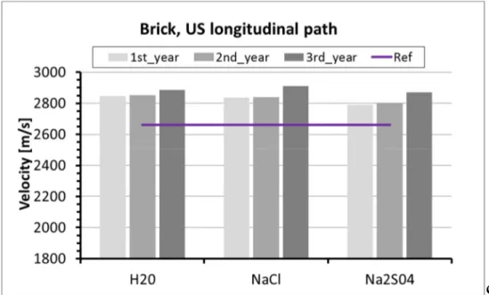
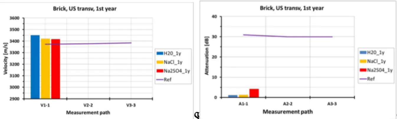
First of all, the damaging effects of the diverse natural ageing contaminations are investigated on several tens of single units of masonry building materials. Thus, in chapter 5 the results of the monitoring and the assessment of the weathering consequences on the physical and mechanical parameters of the materials are reported, These effects were evaluated via visual and photographic inspections, and assessed by gravimetric and dimensional surveys, non-destructive (ultrasound) and non-destructive tests, repeated at the end of each ageing season. In chapter 6, the same problematics are qualitatively and quantitatively investigated with reference to naturally aged full-scale walls by means of repeated non-destructive (such as sonics, IR thermography, GPR radar, …), micro-destructive and advanced monitoring techniques (wireless sensors for electrical impedance of dissolved chloride salt movements), also in order to evaluate the sensitivity of the non-destructive imaging diagnostic techniques to moist and salt decayed areas. In perspective, this work is valuable for transferability and further applications on real structures on-site.
In the next chapter it is reported of non-destructive sonic tests carried out on the sets of small walls and masonry assemblies, either subjected to natural or accelerated ageing, in order to evaluate differences/similarities of the effects and evolution of the environmental decay in masonry which is replicated by means of the two different treatments (chapter 7).
For the same series of specimens, the mechanical evaluation of the degradation effects is reported first with reference to the uniaxial compression tests carried out on small walls subjected either to natural or artificial ageing, at increasing decay levels prior to the mechanical testing (chapter 8) and, secondly, with reference (chapter 9) to axial and eccentric compression tests (2 grades of eccentricity) or shear tests performed on six-brick columns and
triplets respectively. Again, brick columns and triplets had all undergone accelerated ageing, and 4 series were mechanically tested after being subjected to increasing number of crystallization cycles. Main aim of the activities described in these two chapters was to assess the variations of masonry characteristic mechanical properties caused by aggressive environmental exposure. On the occasion of these mechanical tests an innovative non-destructive image monitoring procedure was on-purpose implemented, via digitl image correlation. In the future, it is hoped to transfer this application in-situ on historic masonry. Finally, a comparative analysis of the results is proposed and the outcomes discussed (Chapter 10).
1.4. Definitions and clarifications
For clarity of reading the remaining text and also as a preview, some proposed definitions that are worth at least in the context of this thesis are herein reported.
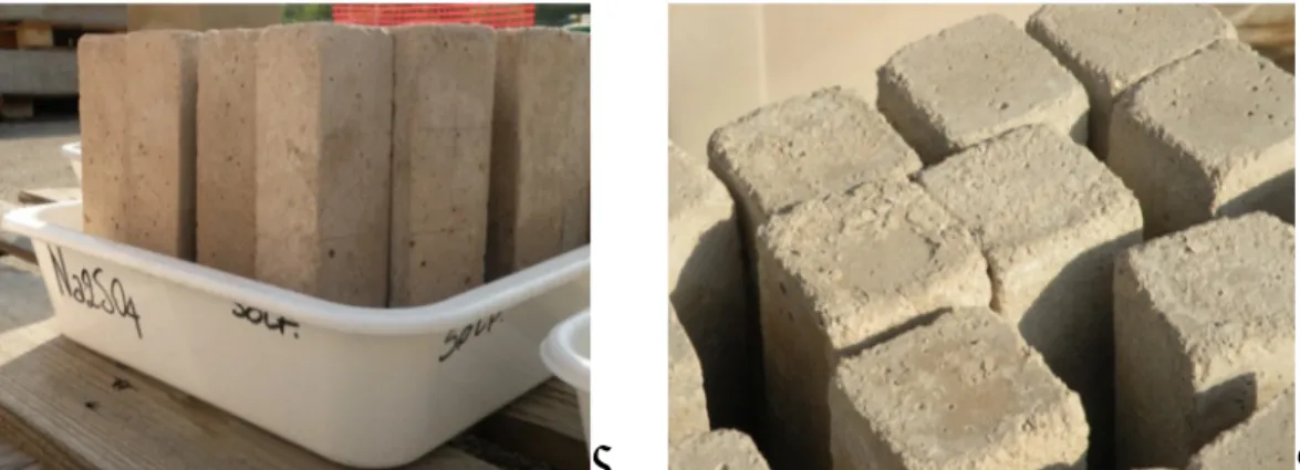
- Natural weathering or natural ageing: outdoors exposure to real weather during the summer seasons only, including rain water, in addition to water or low-concentrated sodium chloride or sodium sulphate brine artificially supplied at the base of specimens and naturally sucked in masonry by capillary rise.
- Ageing summer/season/year: used here as synonyms, they refer to a single period of natural weathering by outdoors exposure of the samples, usually lasting 5-6 months. - Artificial or accelerated weathering/ageing: the masonry specimens undergo cycles of
total immersion in tanks of highly-concentrated sodium sulphate brine followed by treatment in climatic cell while varying the boundary conditions (air temperature and relative humidity) to force salt crystallization.
I would like to acknowledge that my Ph.D. activity has started in the framework of a collaborative 7FP EU research project – SMooHS, Smart Monitoring of Historic Structures - concluded in November 2011 and it has afterwards continued up to now. This aspect is underlined in order to explain why some experiments presented herein had external collaborations.
1.5. First overview of masonry specimens built in the laboratory
2.
Weathering effects in masonry materials
due to salt transport and crystallization
Porous masonry materials such as stone, brick and mortar exposed to the environment inevitably undergo aesthetical or substantial changes in character due to physical, chemical or mechanical processes. Architects, restorers and experts in the field of buildings’ conservation commonly used the word weathering to refer to all such changes.
More specific words as decay, deterioration or degradation are then used, respectively, when these modifications affect the intrinsic properties of a material or when they are associated with a worsening of the material´s characteristics or a decline in its condition or functional capacities (ICOMOS 2010).
These changes are very common in historic or existing masonry structures outdoors exposed and they are strictly related with the presence and movements of water in all its status forms (liquid, gaseous and solid) into the material pores.
The mechanisms responsible for such damages in construction materials represented a topic of continuous research since the 1960´s (Watt 2000, Larsen 1990) because of their complexity, as they involve a large number of parameters usually inter-connected, and because of their economic implications.
Weathering processes, indeed, are the results of a complicated interaction between the structure itself and the specific micro-climate conditions to which it belongs; it is thus necessary to know and fully understand the basics of the controlling mechanisms of the weathering processes, prior to study any method or technique for evaluating, preventing or repairing these damages (Scherer, internal stress).
This chapter is aimed at giving a brief overview on the literature on this topic. It deals first with the basic causes and the physical-chemical principles related to the weathering of masonry, especially in presence of water and salts. The salt-water systems are then described, with particular attention to the behaviour of two salt solutions which are frequently involved in masonry deteriorations: sodium chloride and sodium sulphate solutions. Finally, a description of the decay effects due to environments and of the available tests and existing standards for their evaluation is reported.
2.1. Moisture transport and capillary rise phenomenon
Water plays an important role on weathering of masonry construction materials being the principal responsible or the promoting agent of different types of decay such as:
- chemical decay, like corrosion, hydration or oxidations which may occur i.e. in presence of aggressive pollutants;
- physical decay, due to mechanical stresses induced into the material pores i.e. by freeze-thaw cycles, thermal expansion or salts crystallization/hydration;
- biological decay, as mould growth or biological colonization (ICCROM 99, Guerra 2011).
Water may penetrates into the material pores in different ways such as by capillarity, percolation or vapour.
The capillary rise process ids one of the most common process and it is responsible for salts’ transport and crystallization.
2.2. Effects of salts on porous masonry materials
Salts, typically chlorides, sulphates and nitrates, can derive from different sources i.e. they can be already into the building materials or in the water used for the mortar mix, they can be absorbed from the ground through capillarity, they can enter into the structure from the atmosphere, especially in high-industrialized area or near the sea. In the case of capillary rise, phenomenon of our present interest, the damaging mechanism follows this process: the dissolved salts are moved by water into the material pores until a certain height, function of the capillary and hydrostatic pressure; then, in presence of water evaporation and in certain specific microclimatic conditions, different for the diverse types of salt, they may crystallize on the surface or beneath it.
In the first case, the salt crystals became visible as white depositions, called efflorescences and may seriously affect the conservation of the surfaces, also if plastered; in the second case of salt crystallization, known as sub-florescence the crystals’ volume increase may generate internal pressure greater than the resistance of the pore walls and thus cause material degradation, such as blistering, delamination, formation of cracks, etc. Repeated cycles of salt hydration/crystallization may worsen the process and terribly increase the amount of decay.
2.3. Evaluation of decay effects in masonry
Much has already been done with this respect to the evaluation of decay effects but much has to be done. As an example, there is still a strong interest in finding reliable and repeatable ways of determining the macroscopic hydraulic properties of porous media as stated by different authors [4-5]. In order to achieve this aim and obtain a detailed knowledge about the damp rise and the diffusivity mechanisms in masonry, the characteristic hygrothermal properties of the single building construction materials, such as brick units and mortar samples, as well as the properties of masonry assemblies have to be known. This information would be important both from an experimental view point as it would allow a deeper understanding of the degradation processes, helping in finding proper methods for diagnosis and for appropriate treatment solutions, and from a numerical point of view in order to assess and calibrate ad-hoc models able to i.e. estimate the evolution of the decay mechanisms in historical masonry.
At this regard, few international testing standards are available and they are concerned with the behaviour of single masonry constituent materials in contact with water. As a matter of fact, the dangerousness of the presence of water in a structure, which may cause modifications or decay in the materials, has been recognized from International Technical Committees and, i.e. it has been found that an increase in the value of the water absorption coefficient can be related to an alteration process [6]. Thus, the norms mainly describe water absorption tests to be performed on sets of small samples (typically 3 or 6 cubes with 50 mm side) of hardened mortars [7, 8], natural stones [9,10] and, not well specified specimens of porous inorganic materials used for and constituting cultural properties [11]. In detail, for both mortars and natural stones, the laboratory tests consist in positioning a specimen, previously dried to constant mass, into an uptake container with a constant level of tap water at room temperature (and atmospheric pressure) and in measuring its weight at different time periods (according to the type of material or the speed of water absorption) until constant mass. Thus, the water absorption coefficient can be determined. This parameter is defined as the amount of water absorbed per unit area (expressed in grams/cm2) as a function of time from a sample with one surface in contact with deionised or tap water [11, 12] or as percentage obtained by the ratio of the mass of the saturated sample to the mass of the dry specimen [9].
A slight difference has been found in [11] as this European Standard specifies a method, that may be applied to porous inorganic materials (either untreated or subjected to treatment or ageing) to determine both the amount and the rate at which a specimen absorbs water by capillarity through a surface in contact with water. Thus, it allows the evaluation of the water absorption coefficient as well as of the capillary water penetration coefficient, defined as “the slope of the curve obtained reporting the height of the water front migration versus the square root of time, calculated by linear regression”.
The behaviour of assemblies of 2 or more construction materials (i.e. brick masonry) in contact with water is not considered at all in the norms. In addition, the effects of dissolved salts within porous media has not yet been included in these types of tests. The only references to salts are to be found in the few standards available in the field of accelerated
ageing tests of materials [13-15], which, anyhow, refer to very small specimens of stones, marbles or brick units and do not really explain the relationship between the obtainable results in the case of accelerated ageing and the ones to be achieved by natural environmental ageing.
2.4. Conclusions
Although many characteristics of the salt damaging processes as well as some of their effects are well-known (i.e. appearance of the decay, changes in the material pores, sensitivity of different materials to this decay process …), very little is known on the variations of the resistant capacity of masonry structures when subjected to prolonged salt capillary rise. Understanding better this complex correlation would be very important from a structural viewpoint.
3. Non-destructive techniques used in the
experimental work
The experimental work has foreseen the application and validation of several on-site applicable non-destructive techniques (NDT) and laboratory destructive, mechanical, tests. According to the testing aims, these methods have been chosen after a state-of-the-art review, prior to the beginning of this PhD, during the 7th FP EU project SMooHS, because suitable for diagnose and assessment of masonry structures and for the evaluation of environmentally driven problems considering structural and materials parameters.
The non-destructive imaging techniques employed exploits different physical principles (i.e. acoustic or electromagnetics) and are aimed at evaluating qualitatively and quantitatively the effects and evolution over time of replicated weathering process in on-purpose designed brick walls and masonry assemblies as well as on the single units of building constituent materials. The different types of laboratory mechanical tests (concentric and eccentric compression, shear tests) are aimed at addressing the variations on the principal mechanical characteristic parameters of masonry caused by environmental degradation.
In the following, the basic principles, the testing equipment used and the on-purpose developed testing procedures are described first with reference to the NDT tests and then for the mechanical methods.
3.1. Ultrasonic tests
Ultrasonic (US) tests are a well-known non-destructive acoustic technique based on the propagation of high-frequency waves, typically between 20 and 100 kHz, inside a material. In the field of civil engineering, these tests are largely used to estimate the elastic and mechanical properties of concrete, to detect the presence of defects such as cracks, voids, inhomogeneities in concrete, stone and masonry elements and structures and, also in combination with other techniques, to assess the health-state conditions of structural elements. The ultrasound tests are a well-established non-invasive diagnostic techniques for concrete structures, as testified by several available standards (EN 12504-4:2005, ASTM C 597:02, EN 13791:2007) and natural stone (EN 14579-4:2005). Anyhow, researches are still on-going with reference to concrete structures in order to better investigate the accuracy of this technique, i.e. by performing comparison with other NDT methods (Pascale e Colla, 2006) or to improve the analysis of wave propagation (Garnier V. et al., 2006). Instead, other researches were aimed at evaluating the potentiality of ultrasound tests in characterizing and locating defects in inhomogeneous materials such as wood (Bucur V., 1999; Maack e Krause, 2008) or masonry (Musolino et al., 2007). With reference to masonry materials, the US assessment of porosity and strength of mortars have also been studied (Voigt et al, 2006; Goueygou et al., 2009) and a more recent work has proved the reliability of ultrasound tests as
applications with good results have been carried out also in historic masonry constructions (Dilek, 2007; Brozovsky et al. 2008, Camplani et al., 2008; Pascale 2008; Salazar et al., 2012).
Basic principles and types of tests
Short vibration pulses are generated by an electro-acoustical transducer (emitter) held in contact with the surface of the investigated element. The so-generated longitudinal or transverse stress waves, after travelling through the material, are then recorded by one or more transducers (receivers) positioned in the opposite or same surface of the element according to the data acquisition mode. The vibration is then converted into an electric signal, which is suitably amplified and continuously visualized on a CRT (Cathode Ray Tube) oscilloscope.
From ultrasound tests, the travelling time, Δ [µs], is measured, and knowing the ideal path length, L, the pulse velocity V [m/s], which is the velocity of the P- or S-waves propagation, is calculated:
V= L
Δt 3.1
This velocity, is a function of the characteristic parameters of the material crossed:
) 2 1 )( 1 ( ) 1 ( d l E V 3.2
where: Ed = dynamic modulus of elasticity of the material, ν = coefficient of Poisson of the
material and ρ = density of the material.
Thus, from this equation, knowing the values of ν and ρ of the specific material tested and measuring V, it is possible to evaluate Ed. Then, from the dynamic modulus, an estimation of
the static modulus of elasticity, E, could be performed, by reducing the first value of about a 30%.
In ultrasound tests, the wave attenuation is also measured. The attenuation is the decrease in the wave amplitude during its propagation within a material and it is due to the divergence of the radiation pattern (geometrical attenuation) or to absorption and scattering phenomena depending upon the characteristics of the crossed material.
The structural attenuation, A [dB], has usually the greater influence and depends upon the acoustic pressure (Figure 3.1):
A=20 log10 P0
Figure 3.1: Amplitude of the emitted (P0) and receive signal (P)
For each specific test, it is recommended to evaluated the obtainable resolution, . This is the minimum detectable dimension of a defect and it is a function of the wavelength, , usually defined as a half or a third of the wavelength itself, was calculated for this specific case (Pascale, 2008). The signal wavelength, indeed, depends upon the velocity of the P-waves, VP, into the specific material considered and the maximum signal frequency, f, according to Eq. 3.4:
λ= 3.4
Testing equipment
In this experimental work, ultrasound tests were performed by means of a commercial Olympus EPOCH 1000 available at the LAGIRN laboratory of our department and made of a portable unit and a signal amplifier was employed. This system is characterized by a pulse rate frequency up to 6 kHz, an equivalent measurement rate for the receiver, a gain range from 0 to 110 dB and full EN 12668-1 compliance [3]. A couple of 1MHz frequency probes for P-wave detection, 13mm in diameter, were used. These probes were chosen taking into account on the one hand, the small dimensions of the specimens to be tested (single units of bricks and mortar prisms, see chapter 5) and on the other hand the high resolution signals required which were capable of detecting also small anomalies and/or differences between the mortar prisms belonging to diverse sets.
Testing procedure
Ultrasound tests can be performed in three types of signal transmission mode, according to the relative positions of the emitter and the receiver: direct, semi-direct or superficial transmission tests (Figure 3.3).
Figure 3.3: Ultrasonic tests, data acquisition mode: direct transmission (left), semi-direct
transmission (centre), superficial transmission (right)
In this thesis, only US in direct transmission mode were considered to study brick units and lime mortar prisms in different ageing conditions. Longitudinal and transversal paths on the samples were considered.
The measurements were carried out by positioning the transmitting and receiving probes on each reading stations of the samples by means of a plastic clamp in order to ensure the same contact pressure, independently from the operator. In addition, a dry coupling of the transducers was obtained by interposing a latex sheet, 0.5 mm thick, between the surfaces of the probes and the sample, in order to ensure air removal and, in the same time, avoiding that remaining traces of coupling agents (usually gel or greasy pastes) would enter the material pores and alter the suction/evaporation mechanisms.
Prior to start with the data acquisition, for each set of samples, a calibration of the US signal was performed, by using a specific metal or plexiglas calibration bars with the aim of determining the reference values of time of flight and signal attenuation to be detracted from the single US measures.
3.2. Sonic tests
Sonic tests are an acoustic non-destructive technique, based on the variations of signal velocity and attenuation of low-frequency waves generated by means of an instrumented hammer and received by a transducer, generally an accelerometer after having crossed a material section. These tests are suitable for the detection of defects such as cracks, voids and inhomogeneities, the evaluation of the morphology of the structure and of its characteristics mechanical properties as well as assessment of the health-state of structures like brick, stone masonry and natural stone elements. Sonic tests are used for the damage detection and evaluation of material properties also in historical buildings. They are preferred to ultrasonic tests in cases of large and inhomogeneous elements because of their highest penetration depth. In the fields of civil engineering as well as in cultural heritage sites, many researches and studies carried out in the last twenty years, have proved the reliability of sonic tests in recording useful information about hidden details and defects of a structural element and internal geometry, giving an overall qualitative view on the health-state conditions and structural integrity of the investigated structures and buildings.
Moreover, several studies have proved, by comparing this methods with other diagnostic techniques such as GPR radar, the feasibility and accuracy of the sonic tests for assessing the effectiveness of repair techniques or grout injections on structural masonry walls, i.e. performing the tests before and after the injection it was possible to estimate whether the grout is diffused inside the masonry or not (Binda et al. 2001; Russo et al., 2004; Anzani et al., 2006). Promising results were also obtained with regards to the evaluation of damages in historic stone elements (Cappabianca et al. 2008) Recent advancements on the data acquisition in superficial transmission mode and data analysis procedures allowed to visualize the values of sonic velocity and signal attenuation as 2D images (sonigrams), easing the data interpretation (Colla e Pascale, 2007; Colla et al. 2008). On-site experimental campaigns were successfully carried out also for the assessment of the mechanical properties of the masonry a cultural heritage, historic masonry tower (Colla e Pascale, 2010).
Basic principles and types of tests
In sonic tests low-frequency elastic waves (20Hz – 20KHz) are generated by an instrumented hammer on the surface to be investigated. The elastic shock excitation generates stress waves hat propagate inside the material, as longitudinal or transverse waves. A receiver transducer, usually a piezo-electric accelerometer receives the pulses. The vibration is then converted into an electric signal, which is visualized on a CRT oscilloscope or on the screen of a personal computer.
For each measurement path, a pair of waveforms is recorded by a data acquisition unit: the signal generated by the hammer and the received signal after propagation in the material. Sonic investigations can be performed in different ways, depending on the relative position between the hammer and the receiver: direct, semi-direct or surface transmission may be carried out (Figure 3.4). In direct transmission mode, or transparency, the hammer and the receiver are placed on two opposite surfaces of the structural element, on the same axis, so that the direction of transmission pulse is perpendicular to these surfaces. Instead, in the
surface method, or indirect transmission, both hammer and accelerometer are placed on the same surface, and measurements are taken along a straight line, vertical, horizontal or diagonal. Finally, in the semi-direct transmission mode, the stations of signal emission and reception belong to adjacent faces, but in some cases even opposite.
As for ultrasound tests, the so-called time-of-flight, ToF, in µs is measured (Figure 3.5) and the apparent pulse velocity, in m/s, is calculated, by knowing the ideal length of the wave path (Eq. 3.1). The wave attenuation, A (Figure 3.6) is also measured and reported to a dimensionless value with respect to the amplitudes of the transmitting (AmaxTx) and receiving
signals (AmaxRx – AminRx) by means of:
A=20 log10A0
A 3.5
where A0 = Amax Tx, and A = Amax Rx - AminTx.
The variations on the values of the pulse velocity which are related to the density and the mechanical properties of the material, also in combination with the changes in the values of attenuation, for more accurate results, allows evaluating the homogeneity of the investigated material.
Figure 3.4: Sonic tests, data acquisition mode: direct transmission (left), surface transmission
(centre), semi-direct transmission (right)
Figure 3.6: Sonic tests, measure of the amplitude of transmitting (left) and receiving signals
(right)
Testing equipment
The sonic tests instrumentation consisted in an …. Hammer with a beryllium tip,
Micro-accelerometer
Figure 3.7: Sonic tests, testing equipment, hammer and receiver
Testing procedure: data acquisition and analysis
Prior to start with the data acquisition, the measurement stations have to be selected, usually by tracing rectangular grids on the surface/s to be investigated. The measurements positions and/or grids have to be chosen according to the testing aims and traced on the studied elements. No other surface treatments/preparation are required.
In this thesis, sonic tests were carried out in direct-through transmission mode and surface modes on naturally aged full-scale brick walls and naturally or artificially aged small walls and masonry assemblies.
The small walls and masonry assemblies were tested only via direct sonic tests and the measurements performed by placing the hammer and receiver on opposite positions, on the
lateral faces of the specimens, in order to carry out measures along the plane of the wall. Variations in sonic velocity and attenuation are measured.
On full-scale walls a rectangular grid of measurement points was marked on both main wall surfaces prior to perform direct sonic tests (Figure 3.8). The instrumented hammer and the receiver were progressively moved along the stations of the grid but always facing each other, starting from the top left corner of the wall front face.
On each position, the values of time-of-flight, signal velocity and signal attenuation were evaluated. The results beyond being visualized in graphs reporting the parameters as a function of the measurement stations, are post-processed together with the geometrical (x, y) coordinates of each station, by using a mapping SW in order to obtain grey-scale or coloured 2-D images which allows an easier visual interpretation and comparison of such results.
Figure 3.8: Example of measurement grid for direct sonic tests in full-scale walls (left),
“Surfer” command window for plotting sonic results as coloured or greyscale maps (centre), example of a 2D direct velocity maps
To perform sonic tests in superficial transmission modes on the full-scale walls, both the hammer and the receiver (micro-accelerometer) are placed on the same wall surface (front side). In this case, the grid selected was not rectangular, but instead the stations were positioned at the intersection between 8 concentric circumferences of radius varying from 0.1m to 0.8m and 16 diameters with different angles, with the receiver staying still at the center of the grid and the transmitter moving on each station (Figure 3.9). Also in this case, data were analysed in terms of time of flight and signal velocities.
Figure 3.9: Example of measurement grid for surface sonic tests in full-scale walls (left), data
3.3. GPR ground penetrating radar
The GPR radar is a non-destructive technique based on reflection of electromagnetic signals born in the 50’s in the geophysical field with specific tasks of soil investigation and only since the ’80 has started to be use in the field of civil engineering. It is a global and fast technique, on-site applicable, which allows to scan large areas of walls, pavements and other elements, including historic constructions and thick stone or brick masonry. Among other applications, it is suitable to evaluate element and layer thickness, also in case of multi-whyte walls and to detect inner defects such as voids, inclusions, detachments, cracks and in-homogeneities in structural elements made of several different materials, like natural stones, stone and brick masonry, concrete. GPR allows also to assess the health-state conditions of new and historic structures and the presence of moisture and salts within walls.
This method is suitable for testing concrete and masonry structures also of large dimensions like bridges (McCann, et al. 2001).
Although it is a rapid, no-contact high resolution method for detecting and mapping features in engineering applications but it cannot be used for high resolution soundings in great depth ranges or in environments with high electrical conductivity. The range and resolution of GPR decreases with the presence of conductive materials like brine or conductive pore water. At saline contents of 0.05% by weight 900 MHz bow tie antenna were significantly attenuated. When testing through soil, the best results were obtained when using radar through dry soil. (Colla et al. 1997)
Successful results were obtained Detail knowledge obtained about the construction has a positive fall back on the structural model and on the analyses aimed at evaluating the load carrying capacity and safety of the object. It seems very promising the possibility of merging the GPR data about the hidden wail geometry with the impact-echo and sonic data about the time of flight of stress waves in different masonry patterns, in order to estimate homogeneity and constitutive parameters of a mechanical model of the masonry. Thermography inspection have also shown to be very useful in this case of archaeological cultural heritage benefiting from high protection, providing useful information about the health and patterns of superficial material layers.
Colla, C., De Miranda, S., Ubertini, F., 2008, On site diagnostic investigations for the assessment of the House of the Wooden partition, in Herculaneum, in On site assessment of concrete, masonry and timber structures SACoMATiS 2008. Proceeding of the First International RILEM Symposium, L. Binda, M. di Prisco, R. Felicetti, Vol. 2, 945-954.
The applied diagnostic procedure has served to identify the characteristics of the elements that determine the structural behaviour. The
Basic principles
Short electromagnetic pulses (frequency range 500-2500 MHz) are propagated into the structure thanks to an antenna moved on the surface, along survey lines. In reflection mode, the reflected signals are picked up by a receiving antenna moving on the same surface as the transmitter; in transmission mode, the receiver is placed on the rear surface of the element
(this operating mode is less frequently adopted). The propagation of the radar signal depends on the condition and dielectric properties of the materials encountered. The signal velocity and attenuation are the factors that describe the propagation of the radar waves into the materials. These parameters are a function of the relative permittivity, conductivity and magnetic permeability of the materials, which also determine the signal power reflected at boundaries where the dielectric properties vary.
Testing equipment
Signal generator and control unit with data storage functions and monitor for real-time data visualisation. One or more antennae boxes containing a transmitting and a receiving antenna (usually dipole antennas). Survey wheel can be attached to antenna for precise recording of survey length. After data acquisition, data elaboration is performed on a PC with appropriate SW
Figure 3.10: GPR testing equipment and antenna
Testing procedure: data acquisition and analysis
Choice of antenna frequency must be suited to characteristics and thickness of materials investigated, dimensions and location of defects sought. Necessity to access a sufficiently wide testing surface in function of penetration depth and antenna dimension.
3.4. Infrared thermography
Infrared thermography (IRT) is a non-destructive investigation technique, which is becoming more frequently employed in civil and architectural inspections, in the diagnostic phase, in preventive maintenance or to verify the outcome of interventions. On historic structures, it allows investigating details of construction (e.g. hidden structure or masonry texture behind the plaster), damage and material decay (e.g. moisture, plaster detachment from a wall, detachment within a fresco, cracks pattern evolution, temperature pattern evolution,
Infrared thermography is a non-destructive investigation technique, which is becoming more frequently employed in civil and architectural inspections, in the diagnostic phase, in preventive maintenance or to verify the outcome of interventions. On historic structures, it allows investigating details of construction, damage and material decay. In order to obtain more detailed information IRT can be used with other NDT techniques (e.g. ultrasound, radar etc.)
Applications of infrared thermography in civil engineering are not limited to the identification of heat losses in building envelopes; infrared thermography methods enable localisation of voids and other irregularities in the near surface region, localisation of plaster delaminations, detection of moisture in the near surface region etc.
Masonry and especially historic masonry has a very inhomogeneous structure containing several different materials (brick, stone, mortar, plaster, wood, metal etc.) with different thermal properties; in this cases thermography is a very reliable method to assess the following testing problems in the surface near region: detection of plaster and tile delaminations, location of mounting parts behind plaster, characterisation of masonry structure behind plaster, location of empty joints, detection of enhanced moisture, location of delaminations of strengthening materials.
In the following, some relevant information arising from literature review are summarized. Very interesting is the case of the massive masonry of the Historical Arsenal of Venice (Grinzato et al., 2002 [5]) where IR thermography has been applied successfully for the knowledge of wall bonding, moisture mapping and the measure of the thermal diffusivity of bricks and plaster.
A review of results (hidden structure identification, adhesion of frescoes testing, cracks mapping and air flows study) given by thermography applied for the conservation and monitoring of the Scrovegni Chapel at Padova, frescoed by Giotto, is presented in [6] (Grinzato et al., 2002).
Different thermographic techniques for frescoes NDT were compared by Carlomagno et al. and reported in [7] (2002). The authors evidenced how the choice of the most appropriate thermographic technique, for non-destructive evaluations, depends on several considerations linked on both material characteristics and test objectives.
The application of infrared thermography to the non-destructive testing of concrete and masonry bridges was evaluated by Clark et al. ([8], 2003), while Avelidis et al. ([9], 2003) evidenced the importance of proper emissivity values for building diagnostics. Since in
literature there is little work that has been published on emissivity values for building materials (mostly historical buildings) at a range of temperatures, the results that arise from this research work, provide valuable information to the thermograph whose investigation is concerned with buildings and historic complexes (however the best approach, whenever possible, is to measure emissivity on site).
Some others interesting applications of infrared thermography for the investigation of historic structures by Avdelidis et al., 2004 are reported in [10]; the authors concluded that infrared thermography provides significant information for the assessment of materials and techniques for the protection of cultural heritage. In particular, it can be used efficiently for the assessment of conservation materials and techniques on the subject of surface cleaning, stone consolidation, restoration of masonry by repair mortars, as well as to disclose any substrate features, such as tesseræ on plastered mosaic surfaces.
Rosina et al. ([14], 2004) developed an IRT procedures for the monitoring of restoration interventions on ancient building surfaces (i.e. application of protective films, water repellent, restoration of plaster delamination), the surveillance of the risks areas (i.e. risk for dew, infiltration, thermal bridges, window frames).
The use of infrared thermography for non-destructive evaluation of one- and two-layer masonry structures has been examined by Meola and reported in [19] (2007)
Remarkable is also the investigation by IR thermography of Roman archaeological stone masonry structures with thick plaster overlay (Colla et al., 2008 [24]). Particular aims have been to investigate the state of bonding between the plaster and its support, to locate moist areas in a façade wall highly inhomogeneous in terms of plaster materials, surface roughness and plaster thickness, and to unveil construction details hidden under the finishing layer, such as the shape and layout of the masonry units or the inclusion of metal elements. The authors concluded that the information provided by IR inspections outcome is of great significance in terms of acquired knowledge about the archaeological masonry construction and has positive consequences on structural evaluation.
Basic principles
The presence of a subsurface defect modifies the diffusion rate of thermal propagation. Infrared thermography is a contactless NDT technique able to record the distribution of surface temperatures and thus to unveil details of what is under the surface, within shallow depths, or its thermal behaviour.
Passive and active thermography testing procedures can be differentiated. In passive thermography, abnormal temperature profiles indicate a potential problem, and an important measurement parameter is the temperature difference with respect to a reference. Generally, passive thermography is rather qualitative since the goal is simply to pinpoint anomalies. In active thermography it is necessary to bring some energy to the area inspected, in order to obtain significant temperature differences witnessing the presence of subsurface anomalies.
Testing equipment
Infrared thermo camera with a specific wavelength window (depending on the material to be tested), different kinds of lens (depending on the distance from the analyzed surface, on the surface dimensions and on the minimum dimensions of the expected defect), PC, post-processing software.
Figure 3.12: Data acquisition
3.5. Laser scanner
In this thesis, a triangulating desktop laser scanner was used, which is proven to be a reliable technology for non-contact surface measurements. The technique is called triangulation because the laser spot, the camera and the laser emitter form a triangle. Exploiting the principle of the topographic forward intersection it is possible to determine the position of a point in the 3D space defined by the instrumental reference system (Fig. 2). The distance between the laser emitter and the camera sensor (representing one side of the triangle) is known by the constructor specification, and it is called “baseline” (b). The out-coming angle (α) of the laser beam is also known by a prior calibration of the rotating mirror. Then the laser beam undergoes a reflection on the targeted surface, and its footprint on the receiving sensor (usually a CCD or CMOS) makes it possible to calculate the angle (β). These three informations (α, β, b) combined with the trigonometric formulas (1) and (2) fully determine the coordinates of the points cloud in which the surface can be discretized.
Following a process of triangulation, the points cloud can be converted into a mesh of triangles, which constitute the 3D surface of the object. If the device is able to capture also the color RGB information
Basic principles
X, Y, Z) coordinates of a single point
Testing equipment
The laser scanner used in this work is produced by NextEngine Inc. and is based on Multi-stripe Laser Triangulation (MLT) technology. The laser scanner acquires the data in two different modes corresponding to two different baselines: Macro mode and Wide mode. Some constraints on the distance between the object and the scanner are given for each mode (Tab. 1). The choice of the scan mode depends on the object’s size and the desired output accuracy.
NextEngine HD
(desktop triangulation scanner
Table 1. NextEngine laser scanner specifications.
Dimensions 224 x 91 x 277 mm
Macro Mode Wide Mode Field of View 13x10 cm 35x25 cm
Working distance 18 cm 40 cm
Accuracy ±127 µm ±381 µm
Resolution 200 DPI 75 DPI
Texture density 400 DPI 150 DPI
Points/sec 50000 50000
The scanner mounts a couple of twin arrays of Class four 1M 10-mW solid-state lasers with custom optics at a 650-nm wavelength. The scanner also features twin 3 MP CMOS RGB image sensors, and built-in white light texture illuminators [7, 8] This technique was chosen because it is contactless, rapid and capable of providing quantitative information, thus it could be helpful in order to monitor the degradation processes caused by moisture and salt
3.6. Digital image correlation
Finally, an additional innovative non-destructive procedure was considered to evaluate the decay progress and evolution in outdoor walls based on the digital image correlation technique.
The Digital Image Correlation (DIC) is a non-destructive, contactless, optical technique which allows the determinations of high-definition full-field maps of displacements and strains of a surface object subjected to an external force. The method, 2D or 3D, exploits the principles of photogrammetry, digital image processing and stereo-images and it allows a continuous data acquisition. It employs a mathematical algorithm to compare digital images taken at different deformation states of a specimen by means of 1 or 2 digital cameras. This comparison is based on tracking the position in the consecutive, subsequent images of a random speckle pattern applied to the investigated surface prior to the test by using appropriate patterning techniques (spray painting, cotton swab, stencil, speckle patterning, air brush, etc.) [...3Vancouver, + general?] (Fig. 1). The results obtained by means of the DIC technique, in terms of displacement, deformation and strain fields are displayed as greyscale or coloured maps [21 8*]. 38, 40–46].
Figure 3.13: Monitoring over time of the displacement of 1 point [...] cambiare scritta assi
1.1. Basic historic information and principle of DIC
The DIC technique was developed in the early ‘80s at the University of South Carolina as a 2D method to measure the in-plane displacement field of an object while it is undergoing a deformation or a movement. In this case, one digital camera acquires the images and dedicated software compares the reference, non-deformed image with the subsequently recorded deformed images (Fig. 2 left). This process follows different steps: firstly, the reference image is divided into sub-images, or square subsets, which are centred on a point of interest –where the displacements will be calculated-. Each sub-image is then used to track the corresponding location of each control point in the deformed image, by means of a correlation function, until reaching the maximum correlation coefficient between the reference subset and the “deformed” subset, obtaining the displacement of the considered point (Fig. 2 right). Then, the same procedure is repeated to calculate the displacements for all points and images [tesi scaric 12/11; H. Song et al. / Tectonophysics xxx (2013) xxx–xxx &
(Pan et al., 2009b; Sutton et al., 2009; Zhang et al., 2006)]. Fig. 2 di H.Song??? W.H. Peters and W.H. Branson [50].
This simple methodology is appropriate for planar specimens and it gives accurate results only if the specimen is parallel to and at a constant distance from the digital camera for the entire duration of the experiment in order to discard or at least minimize the effects of out-of-plane displacements. In this case, indeed, the monocular vision of the sample allows detecting only in-plane displacement (u, v) and corresponding deformation fields (εx, εy, γxy).
Figure 3.14: Digital camera and relative monocular vision (left); greyscale correlation
between un-deformed and deformed sub-image (right) [DICmanual & Tung et al 2010]
A 3D version of the DIC method has been implemented at the beginning of this century, in order to measure the out-of-plane motion [...]. This procedure is based on the simultaneous acquisition of pair of images, by means of two CCD cameras, placed in front of the investigated object with different angles (Fig. 3). The post-processing software analyzes and compares each couple of deformed images to the pair of reference images by applying first a stereo imaging equation and then a correlation algorithm (comparison of images pixel by pixel). For an accurate determination of the 3D coordinates (x, y, z) and the 3D displacement vector [u(P), v(P), w(P)] of each point P of the images, it is required to calibrate the DIC system prior to the test, in order to calculate the intrinsic and extrinsic parameters of the digital cameras set-up (distortion of the lens, relative distance of the cameras, orientation of the cameras with respect to the object surface, ...) which are characteristics of the specific stereoscopic configuration used [A; vet spost???]. The calibration procedure consists in recording simultaneously a set of images with the two cameras while the position and inclination of a calibration target is changing in front of the specimen to be investigated. The calibration target is usually a white flat plate with a grid of black dots of known dimension and distribution (Fig. 4). The calibration images acquired are used by the software to calculate the coordination system of axis and establish the ideal working plane. The result of the calibration indicates the quality of the adopted configuration and allows selecting the best stereovision system for this specific experiment, which is the one with the least error [A].
a) b)
Figure 3.15: a) Set-up of the 3D DIC method, acquisition of stereoscopic images, b) 3D
vision [Zafar, DICmanual]
a) b)
Figure 3.16: Simultaneous acquisition of couple of reference images, a) from the left camera,
b) from the right camera
a) b)
Figure 3.17: a) a calibration target, b) example of calibration procedure
The accuracy of this non-destructive monitoring technique relies upon several factors including the interpolation and correlation algorithms, the distortion of the lenses, the light distribution uniformity and the quality of the superficial speckle pattern. The first two parameters are distinctive of the equipment selected for the measurements, while the dot
pattern and brightness are defined and controlled by the operator before and during the test. In particular, since a fundamental assumption of the DIC method is that the light intensity field defined on the surface as a digital greyscale does not change during deformation, the operator should guarantee the steadiness and uniformity of the brightness throughout the experiment. Last but not least, the surface preparation plays an important role on the precision of the measurements, thus, the surface has to be treated (Fig. 5) in order to show a random pattern of dots, as much as possible non-repetitive, isotropic and with high-contrast chromatic areas, so that each point of the surface could be recognized and tracked by the DIC [V3 + ...].
a) b)
4. Materials and masonry specimens for
experimental activities
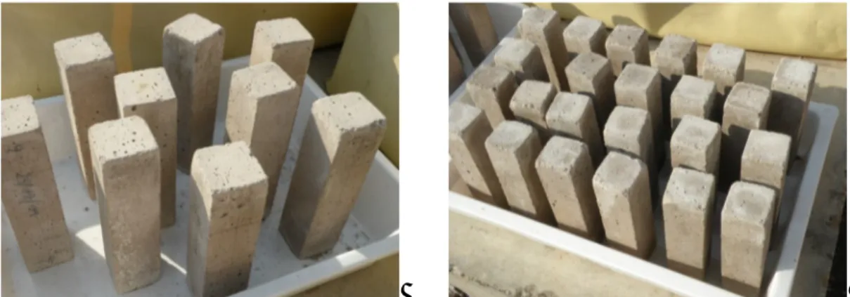
In this experimental research, different series of professionally made full-scale walls, wallets, masonry assemblies (brick columns and triplets) were considered as well as new units of porous building materials (bricks, mortar) (Figure 4.1). After design and construction, firstly they underwent natural or accelerated ageing according to on-purpose developed procedures aimed at reproducing the effects of the decay due to environmental agents such as moisture and salt. Given that the main aim of this thesis was to study the controlled evolution over time of this degradation and hence its effects on the physical and mechanical properties of masonry materials, in a second step they were characterized by means of repeated non-destructive and mechanical tests.
In this chapter it is described the physical-chemical and mechanical characterization of the masonry constituent materials. Following, for the different series of specimens, the design and construction phases, the dimensions, numerosity and aims of test o are reported. Finally, the two implemented ageing procedures are illustrated.
4.1 Material characterization
Given that one of the main focus of the planned experimental work was to follow the decay evolution in masonry since its beginning, new porous construction materials were selected, that is fired-clay bricks and natural hydraulic lime mortar (Figure 4.1). The outdoors phases of the foreseen experiments being undertaken in the Bologna climate, a market search was made for locally produced materials. This search was not successful for the mortar mix.
First of all, as the durability of masonry structures subjected to weathering is function, among other factors of the characteristics of its individual component materials, the physical-chemical and mechanical properties of both bricks and lime mortar were studied by means of several laboratory testing techniques. The main aim of these preliminary tests was to determine with a detailed level of information the starting, undamaged, conditions of the 2 porous materials in terms of characteristic properties. Special attention was paid to those physical properties connected to water and salt transport phenomena. The lab tests described in the following paragraphs were partly carried out at the MPA laboratory of the University of Stuttgart, thanks to a collaboration started in the framework of the 7FP EU research project SMooHS (D5.2-5, SMooHS), and partly at the LISG laboratory of the DICAM Department of the University of Bologna. When possible, standard procedures were followed in order to obtain reliable and replicable results, otherwise, on-purpose procedures partly based on previous research experiences available in literature were developed.
Water would have been important in the experiments, both in the specimens construction stage (mortar mix, wetting of bricks) and in the ageing stage (water and brine sorption/immersion). Therefore, parallel to test the two single building materials, ion-chromatography analysis was carried out in MPA also on to the tap water of the Bologna aqueduct to quantify its salt content and thus, to determine a possible initial value of salt contamination. The results, in terms of anions and cations concentrations, show a low initial amount of chlorides and nitrates but high concentrations of sulphates, equal to 0.0138% -wt. (Table 4.1, Table 4.2). This not negligible initial sulphate content has to be kept into account because it may influence the material’s ageing processes, especially the natural one (§4.5).
Table 4.1: Tap water from Bologna, ion-chromatography analysis: concentrations of anions
(D5.2 part5, SMooHS)
F- Cl- NO3- SO4
2-mg/l % -wt mg/l % -wt mg/l % -wt mg/l % -wt
tap water not detected 37.2 0.004 10.3 0.001 138 0.014
Table 4.2: Tap water from Bologna, ion-chromatography analysis: concentrations of cations
(D5.2 part5, SMooHS)
Na+ NH4+ K+ Mg2+ Ca2+
mg/l % -wt mg/l %-wt mg/l % -wt mg/l % -wt mg/l % -wt
4.1.1 Mortar mix
A commercial ready-mix hydraulic lime mortar was selected. The binder in pure NHL5 while maximum size of aggregates is 4 mm (Figure 4.2). The fresh lime mortar was prepared adding tap water of the Bologna aqueduct to the commercial mix with pure NHL5 binder in the proportions water-to-mortar-mix 0.16 l/Kg. In the experiments, the mortar was used both for construction of the masonry specimens and for casting a high number of mortar prisms of standardized dimensions (b x s x h) 4 x 4 x 16 cm3. These were prepared in the Bologna lab, according to (EN 1015-11): the fresh mix was poured into moulds, in two layers each one compacted with a pestle and then, let to cure in a climatic chamber for 28 days, 7 days at 20°C and RH=95% and 21 days at the same temperature but reduced RH (65%).
To determine the undamaged conditions of the specific mortar used, a complete laboratory testing procedure was carried out, although some physical-mechanical properties of the commercial binder selected were already known from the available technical data sheet, i.e. for the compression strength, it is classified as a class III mortar (UNI EN 1015-11) (Figure 4.2). According to the indications of each specific standard, the different measurements were carried out directly on dust samples of the commercial mortar or on prisms.


![Figure 5.25: Scheme used to obtain the cubes from brick units (left) and set-up of the uniaxial compression test on brick cubes (right) [5]](https://thumb-eu.123doks.com/thumbv2/123dokorg/8161355.126695/83.892.110.784.809.993/figure-scheme-obtain-cubes-brick-units-uniaxial-compression.webp)
