P. Livieri et alii, Frattura ed Integrità Strutturale, 50 (2019) 613-622; DOI: 10.3221/IGF-ESIS.50.52
613
Stress intensity factor for small embedded cracks in weldments
Paolo Livieri
University of Ferrara, Department of Engineering, Italy [email protected]
Fausto Segala
University of Ferrara, Department of Mathematic, Italy [email protected]
ABSTRACT. In the present work, the stress intensity factor (SIF) of embedded small cracks placed at the weld toe is calculated by means of two procedures based on the Oore-Burns integral. In the first approach, the defect is considered as a circular disk and the SIF is evaluated by means of the Oore-Burns weight function. By taking advantage of a suitable change of variable, the singularity of the weight function on the crack border can be removed. In this way, the numerical evaluation of the SIF is possible without the use of specific integration algorithms, although the nominal stress field becomes singular when the crack approaches a V-sharpe notch. As an example, the obtained equations are applied to a defect located in the neighbourhood of a weld toe with an opening angle of 135 degrees under mode I loading. Subsequently, for a crack similar to a star domain with a border expressed by means of the Fourier series, the SIF is given by means of an explicit equation based on the Oore-Burns weight function.
KEYWORDS. Weight function; Stress intensity factor; Three-dimensional crack; Weld.
Citation: Livieri, P., Segala, F., Stress intensity
factor for small embedded cracks in weldments, Frattura ed Integrità Strutturale, 50 (2019) 613-622.
Received: 19.07.2019 Accepted: 17.08.2019 Published: 01.10.2019
Copyright: © 2019 This is an open access
article under the terms of the CC-BY 4.0, which permits unrestricted use, distribution, and reproduction in any medium, provided the original author and source are credited.
INTRODUCTION
he safety factors in the presence of a defect can be verified by the knowledge of the stress intensity factor (SIF) evaluated for an elastic linear material [1]. As proposed by Bueckner [2] and Rice [3], the SIF calculation can be performed by means of the weight function technique. The numerical analysis is reduced to an evaluation of an integral exactly over the region covered by the crack. This method can be applied both for two-dimensional models (crack as a line) or for three-dimensional problems (crack as a surface). In the literature for two-dimensional cracks, there are many formulations in closed form obtained with different methodologies [4]. However, for the three-dimensional cracks, the number of proposed solutions is poor (see, for example, bibliographical references [5–6]). In fact, in many cases the use of
P. Livieri et alii, Frattura ed Integrità Strutturale, 50 (2019) 613-622; DOI: 10.3221/IGF-ESIS.50.52
614
simplifications in the form of a defect is common and it is comparable to relatively simple geometric shapes of which the solution is already known. Usually, by simplifying, the defect is compared to an elliptical equivalent crack [7], while in order to simulate the propagation phase, the defect is continuously assimilated to a succession of ellipses [8–9].
The weight function introduced by Oore-Burns (OB) allows the value of the SIF of three-dimensional cracks under mode I loading with a generic shape to be calculated [10]. Although not exact, this weight function, for the three-dimensional case [11], is an excellent approximation that retains all the typical characteristics of the weighted functions in [12]. In particular, in the case of a semi-axial ellipse (1, b), when eccentricity e tends to zero, the main contribution of the Oore-Burns integral differs from Irwin’s analytical solution [13] for an amount equal to
2
20
e
[14]. The advantage offered by the Oore-Burns integral is to use a generic shape of the defect and the evaluation of SIF at each point of the creak contour without the need to consider the elliptical shape. Unfortunately, the difficulties associated with the analytical calculation of the integral result in the user choosing a particular grid [12, 15]. The resolution strategy proposed in [15] is not always easy to reach the convergence condition. However, it should be emphasised that the Oore-Burns integral is recommended by ASM standards in the case of isolated three-dimensional cracks to have an estimate of the SIF value throughout the profile of a real crack. The designer is therefore motivated to find a solution in closed form for a rapid evaluation of the SIF of a crack with generic form [16].
In this paper, we first summarise an analytical technique to get the Oore-Burns integral as an exact solution. Then, for a circular crack, a simple general equation for the SIF estimation is proposed and, as an example, it is used in the case of welded structures. Finally, the Oore-Burns integral is very well approximated by means of an explicit form for an irregular crack shape similar to a star domain under uniform tensile loading.
ANALYTICAL BACKGROUND
et be an open bounded simply connected subset of the plane as in Fig. 1. We define:
2 ( ) ( ) ds f Q Q P s
(1)where Q Q x y ( , ) , s is the arch-length parameter and the point P(s) runs over the boundary . In their famous work in 1980, Oore-Burns proposed the following expression for the mode I stress intensity factor for a crack subjected to a nominal tensile loading σn(Q) evaluated without the presence of the crack:
2 ( ) 2 ( ') , ' ( ) ' n I Q K Q d Q f Q Q Q
(2)Under reasonable hypothesis on the function σn(Q), the integral (2) is convergent and the proof is based on the
asymptotic behaviour of f(Q) [17].
Figure 1: Inner crack
L
P. Livieri et alii, Frattura ed Integrità Strutturale, 50 (2019) 613-622; DOI: 10.3221/IGF-ESIS.50.52
615 OORE-BURNS ON A CIRCULAR CRACK
et Ω be a fixed set. We can reconstruct the OB integral along the front crack ( by its values along ) by the equation
( , ', ) (1, '/ , )
I n I
K Q K Q (3)
where n( Q) with 0
If we “read” the boundary point Q’ in terms of an angle α that is, for example Ω is star shaped with respect to the origin, (3) takes the simplest form
( , , ) (1, , )
I n I
K K (4)
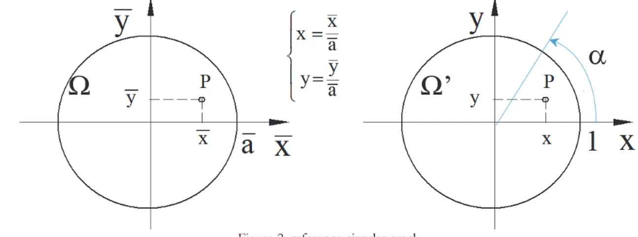
In the particular case when Ω is a disk of radius a centred at the origin of the plane ( , )x y , we denote by (x,y) the system
in dimensionless coordinates x= x a and y= y a (see Fig. 2).
Figure 2: reference circular crack
By definition, for the unit disk Ω’, by (1) and (2) it follows:
2 2 ,0 2 2 1 2 ( , ) ( , ) ( ) cos sin I x y a x y h x y K dx dy x y
(5) With ( , ) 1/ ( , ) h x y f x y (6)
2
2 ( , ) cos sin d f x y x y
(7)By introducing the change of variables
0, ,
0, / 2
(1 sin )cos cos sincos cos (1 sin )sin
x r r y r r (8) where
L
P. Livieri et alii, Frattura ed Integrità Strutturale, 50 (2019) 613-622; DOI: 10.3221/IGF-ESIS.50.52
616
2
2sin sin
r (9)
by some simple calculations 4 sin sin cos
dx dy r d d (10)
2
1 r 2sin (11) r
By using Eqn. (8–11), we have the following expression for the stress intensity factors on the unitary disk
2 ,0 4 ( ) ( , ) sin cos I K x y d d
(12)where the integral is computed on the “longitude”
0, and the “latitude”
0, / 2
.Moreover, the pressure σ(x,y) is “read” in the new coordinates (, φ) for any fixed α, in the sense that x and y are given by (8), with r being defined by (9). If the crack has a radius equal to a the stress intensity factor becomes
2 ,0 4 ( ) ( , ) sin cos I a K x y d d
(13)When
, from (13) we obtain the well-known result: 1
,0 2 ( ) 1.12837 I a K a (14)
We may test the efficiency of Eqn. (13) by comparison with the special cases of nominal stress distribution considered in the literature [18]. Furthermore, many other new examples have been obtained in reference [19] by changing the shape of the nominal stress σ.
SIF FOR AN IRREGULAR CRACK SHAPE LIKE A STAR DOMAIN
or a crack like a star domain as reported in Fig. 3, the Oore-Burns integral can be evaluated without a particular numerical procedure. The Oore-Burns integral will be approximated by means of Riemann sums.
Let us use the Cartesian reference system x,y, Q’ is a point of coordinate (R,α) on . Now we consider a new orthogonal reference system u,v with origin in Q’ with n tangent to (see Fig. 3). A mesh of size δ on can be considered, where δ divides the length of . Qjk of coordinate (kδ, jδ) in the u,v plain, and also Qjk = Rδ(cos(jδ), sin(jδ)).
Pm in Fig. 3 is a point of coordinate mδ with respect to the initial point PO. The Riemann sums KI(δ, Q’) is given by:
( ) 2 ( , ') jk ij I Q A K Q k
(15) where
1 2 2 ij jk m A
Q P (16)The sum (15) is made on 0 m 2 1, Qjk
.
P. Livieri et alii, Frattura ed Integrità Strutturale, 50 (2019) 613-622; DOI: 10.3221/IGF-ESIS.50.52
617 Figure 3: Mesh for Riemann sums
In a previous work [20], we showed that the stress intensity factor can be expressed in the following form:
( ') ( , ') ( ') ( ) I I K Q K Q Q C O (17) where 3 2 2 2 2 1 3 3 2 C J I (18) with 0 sin I d
, 1 0 J
th d and 1 2 is the well-known Riemann function evaluated in 0.5 (C=0.930).
If we know the polar equation of the crack border ( )R , it is convenient to discretise the angle instead of the arc length
s. Now we consider:
2 2
( ) R ( ) R' ( )
(19)
The coefficients (16) assume the form
1 2 2 ( ) jk jk m B Q P m
(20)where Pm is the point of the contour corresponding to m . The coefficient C is then replaced by: 3 2 2 0.889 0.038 ( ) cos ( ) D (21)
where α indicates the position of Q’ for a given origin on the crack border.
The condition Q can be given in terms of a Fourier series as a function of R R ( ) , so that:
0
( ) rcos r sin
P. Livieri et alii, Frattura ed Integrità Strutturale, 50 (2019) 613-622; DOI: 10.3221/IGF-ESIS.50.52
618
By setting x2 y2 , w x i y , Q is equivalent to:
0 1 1 Re r Im r r r r A A w B w
(23)For example, if ( ) 1R Acos with 0 1 2
A
, the condition Q becomes
2 A x 0
(24)
Finally, the equation for SIF assessments can be rewritten as:
( ') ( , ') ( ') ( ) I I K Q K Q Q D O (25) with ( ) 2 ( , ') jk ij I Q B K Q k
(26)(for more details see reference [21]).
NUMERICAL EXAMPLE
n order to verify the accuracy of the proposed procedure, now we analyse two reference cases: the first is a circular defect at the weld toe, the second is an irregular crack under uniform tensile loading.
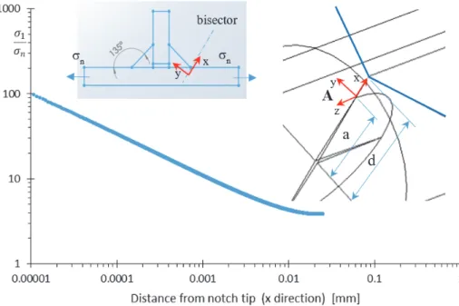
Fig. 4 shows a welded T-joint under tensile nominal stress. In Fig. 4, a disc is put at the weld toe of the welded T-joint and the stress intensity factor is evaluated by considering the asymptotic stress field as reported in [22–23]. The crack lies along the bisector at variable distance d from the weld corner. The T-joint is subjected to a tensile nominal stress, but along the bisector of the weld corner the hoop stress assumes the simple form:
326 . 0 399 . 0 KNr (27)
where KN is the Notch Stress Intensity Factors of mode I and it is equal to 2.46 MPa mm0.326 for a nominal tensile stress σn
of 1 MPa. This value was calculated by means of a careful notch stress analysis by considering the T-joints of Fig. 5 as three-dimensional components without taking into account the effects of the width as analysed in [24].
Figure 4: Welded T-joint under tensile loading.
P. Livieri et alii, Frattura ed Integrità Strutturale, 50 (2019) 613-622; DOI: 10.3221/IGF-ESIS.50.52
619 Figure 5: Circular crack at the weld toe of Fig. 4.
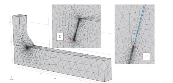
Tab. 1 shows the comparison on the Stress Intensity Factor prediction by means of Eqn. (13) and the results obtained with FE analysis. An accurate mesh is considered and the strand of the principal stress along the crack direction is shown in Fig. 6. The dimensions of smaller elements at the tip of the crack were in the order of 10-5 mm. Fig. 7, as an example, shows the
mesh used for point C.
The difference between the analytical and numerical results is less than 7%. So that, from an engineering point of view, the simple Eqn. (13) can be used for SIF assessments of a small defect in the neighbourhood of the weld toe as made in references [8–9] for semi-circular cracks.
If the crack has an irregular shape not approximable to a disc, Eqn. (25) can be used. In order to estimate the fatigue limit for small cracks or defects under a uniform tensile stress, Murakami and Endo [25–27] proposed 4area as an empirical
parameter to estimate the maximum SIF value of a convex-shaped crack. On the basis of numerous numerical analyses, Murakami and Nemat-Nasser proposed a synthesis relation for the maximum value of the SIF of superficial cracks in the form: KI,maxY area , where Y is a dimensionless factor that assumes the value of 0.629 for lateral cracks [25]. In the case of internal cracks, the value of Y is approximated to 0.5 [25].
P. Livieri et alii, Frattura ed Integrità Strutturale, 50 (2019) 613-622; DOI: 10.3221/IGF-ESIS.50.52
620
Figure 7: Example of mesh used in the numerical FE analysis for the evaluation of SIF for point C (the dimensions of smaller elements at the tip of the crack were in the order of 10-5 mm- a=0.3 mm, d=0.4 mm).
a d A I n K Eqn. (13) C I n K Eqn. (13) A I n K FE C I n K FE [mm] [mm] [mm0.5] [mm0.5] [mm0.5] [mm0.5] 0.3 0.4 1.088 0.795 1.166 0.816 0.1 0.15 0.818 0.583 0.858 0.611 0.1 0.3 0.566 0.488 0.608 0.524
Table 1: Stress intensity factor at points A and C of Fig. 5 for a nominal tensile loading σn (opening angle 135°).
X
Y
0 30 60 90 120 150 180 210 240 270 300 330 1 0.5 0 [deg]Figure 8: Defects (maximum diameter 0.42 mm) Figure 9: Defect in dimensionless form obtained by dividing the radius by half the value of the maximum diameter.
As an example, the calculation procedure described in the previous section is used to calculate the form factor Y, which refers to a small defect detected inside a metallic material. Fig. 8 reports an irregular defect of a maximum diameter equal to
P. Livieri et alii, Frattura ed Integrità Strutturale, 50 (2019) 613-622; DOI: 10.3221/IGF-ESIS.50.52
621
0.42 mm. The dimensionless shape of the defects is reported in Fig. 9, where the half maximum diameter is considered in the dimensionless operation.
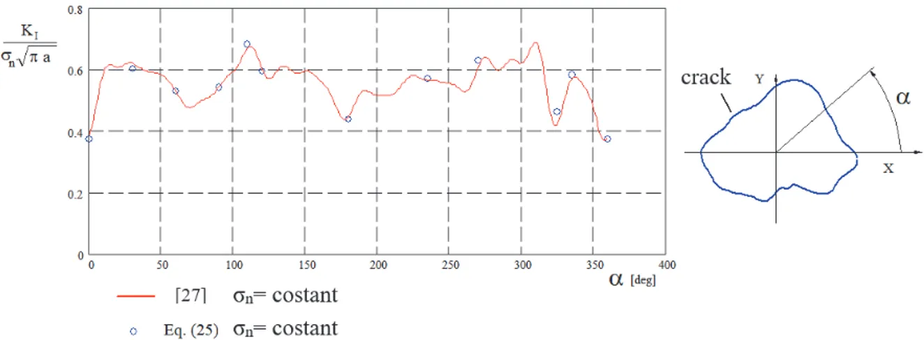
The numerical results are shown in Fig. 10. The symbols represent the numerical values obtained by means of Eqn. (25), whereas the continuous line is the SIF calculated by considering the defect of Fig. 8 as a first order deviation of a circle (see reference [28] for details). In this case after the reading of the border in the Fourier series, the stress intensity factors are given as a sum of harmonic terms weighed by numerical coefficients derived from the Oore-Burns integral in a similar way to that obtained in references [29–30].
Figure 10: SIF of the crack of Fig. 8 under uniform tensile loading σn. (a is half maximum diameter).
CONCLUSIONS
he calculation of the stress intensity factor (SIF) of small circular defects located at the weld toe is possible without the use of specific numerical procedures despite the singularity of the stress field when the distance from the notch tip becomes zero. If the defects do not have a circular form, by taking advantage of the Oore-Burns weight function, a procedure is developed for cracks similar to a star domain. In this way, a more precise evaluation of the SIF is possible and the shape factor of non-convex defects should be estimated. The influence of mode II will be take into account in the future.
REFERENCES
[1] Webster, S., Bannister, A. (2000). Structural integrity assessment procedure for Europe – of the SINTAP programme overview, Engineering Fracture Mechanics, 67(1), pp. 481–514.
[2] Bueckner, H.F. (1970). A novel principle for the computation of stress intensity factors, ZAMM 50, pp. 529–546. [3] Rice, J.R. (1989). Weight function theory for three-dimensional elastic crack analysis. ASTM STP1020, Wei R.P. and
Gangloff R.P., Eds. Philadelphia, American Society for Testing and Materials, pp. 29–57.
[4] Fett, T., Munz, D. (1997). Stress intensity factors and weight functions, Computational Mechanics Publications. [5] Mastrojannis, E.N., Keer, L.M., Mura, T. (1979). Stress intensity factor for a plane crack under normal pressure,
International Journal of Fracture, 15 (3), 247–258.
[6] Wen, P.H., Aliabadi, M.H., Rooke, D.P. (1998). Mixed-mode weight functions in three-dimensional fracture mechanics: static, Engineering Fracture Mechanics 59(5), pp 563–575.
[7] Hobbacher, A. (1995). Recommendation on fatigue of welded components, IIW Document XIII-1539-95/XV-845-95.
[8] Gurney, T.R. (1991). The fatigue strength of transverse fillet welded joints. Abington Publishing, Abington, Cambridge [9] Maddox, S.J. (1987). The effect of plaste thickness on the fatigue strength of fillet welded joints. Abington Publishing,
Abington, Cambridge.
[10] Livieri, P., Segala, F. (2012). Evaluation of Stress Intensity Factors from elliptical notches under mixed mode loadings. Engineering Fracture Mechanics, 81, pp. 110–119
P. Livieri et alii, Frattura ed Integrità Strutturale, 50 (2019) 613-622; DOI: 10.3221/IGF-ESIS.50.52
622
[11] Oore, M., Burns, D.J., (1980). Estimation of stress intensity factors for embedded irregular cracks subjected to arbitrary normal stress fields. Journal of Pressure Vessel Technology ASME, 102, pp. 202–211.
[12] Livieri, P., Segala, F. (2010). An analysis of three-dimensional planar embedded cracks subjected to uniform tensile stress, Engineering Fracture Mechanics, Volume 77, 2010, Pages 1656-1664.
[13] Beghini, M., Bertini, L., Vitale, E. (1991). A numerical approach for determining weight functions in fracture mechanics. International Journal for Numerical Methods in Engineering, 32, pp. 395–607.
[14] Irwin, G.R., (1962). Crack-extension force for a part-through crack in a plate. ASME, Journal of Applied Mechanics, pp. 651–654.
[15] Livieri, P., Segala, F. and Ascenzi, O. (2005). Analytic evaluation of the difference between Oore–Burns and Irwin stress intensity factor for elliptical cracks. Acta Mechanica, 176, pp. 95–105.
[16] Desjardins, J.L., Burns, D.J., Thompson J.C., (1991). A weight function technique for estimating stress intensity factors for cracks in high pressure, Journal of pressure Vessel Technology, ASME, 113, pp. 10–21.
[17] ASM Handbook, (1996). Fatigue and Fracture. Vol 19, ASM international.
[18] Livieri, P., Segala, S. (2016). Stress intensity factors for embedded elliptical cracks in cylindrical and spherical vessels Theoretical and Applied Fracture Mechanics 86(1), pp. 260-266.
[19] Ascenzi, O., Pareschi, L., Segala, F. (2002). A precise computation of stress intensity factor on the front of a convex planar crack. International Journal for numerical methods in Engineering 54, pp. 241–261.
[20] Tada, H., Paris, C.P., Irwin, G.R. (2000). The stress analysis of cracks handbook. Third edition, ASME press.
[21] Livieri, P., Segala, F. (2015). New weight functions and second order approximation of the Oore-Burns integral for elliptical cracks subject to arbitrary normal stress field, Eng. Fract. Mech. 138, pp. 100–117.
[22] Livieri, P., Segala, F. (2014). Sharp evaluation of the Oore-Burns integral for cracks subjected to arbitrary normal stress field, Fatigue & Fracture of Engineering Materials & Structures 37, pp. 95–106.
[23] Livieri, P., Segala, F. (2018). An approximation in closed form for the integral of Oore–Burns for cracks similar to a star domain. Fatigue Fract Eng Mater Struct, 41, pp. 3–19.
[24] Lazzarin, P., Tovo, R. (1998). A Notch Intensity Approach to the Stress Analysis of Welds. Fatigue and Fracture of Engineering Materials and Structures 21, pp. 1089–1104.
[25] Livieri, P., Tovo, R. (2009). The use of the JV parameter in welded joints: stress analysis and fatigue assessment.
International Journal of Fatigue, 31(1), pp. 153–163.
[26] Livieri, P., Tovo, R. (2017). Analysis of the thickness effect in thin steel welded structures under uniaxial fatigue loading. International Journal of Fatigue, 101(2), pp. 363–370.
[27] Murakami, Y., Endo, M. (1983a). Quantitative evaluation of fatigue strength of metal containing various small defects or cracks. Engineering Fracture Mechanics, 17 (1), pp. 1–15.
[28] Murakami, Y., Nemat-Nasser, S. (1983b). Growth and stability of interacting surface flaws of arbitrary shape. Engineering Fracture Mechanics, 17 (3), pp. 193–210.
[29] Murakami, Y, (2002). Metal Fatigue: Effects of small defects and non-metallic inclusions, Elsevier
[30] Livieri, P., Segala, F. (2010). First order Oore–Burns integral for nearly circular cracks under uniform tensile loading. International Journal of Solids and Structures. 47(9), pp. 1167–1176.
[31] Gao, H., Rice, J.R. (1987). Somewhat circular tensile cracks. International Journal of Fracture 33, pp. 155–174
[32] Rice, J.R. (1985). First order variation in elastic fields due to variation in location of a planar crack front. ASME Journal of Applied Mechanics 52, pp. 571–579.

![Fig. 4 shows a welded T-joint under tensile nominal stress. In Fig. 4, a disc is put at the weld toe of the welded T-joint and the stress intensity factor is evaluated by considering the asymptotic stress field as reported in [22–23]](https://thumb-eu.123doks.com/thumbv2/123dokorg/4746815.46749/6.892.176.731.868.1088/tensile-nominal-stress-intensity-evaluated-considering-asymptotic-reported.webp)