Exploring the Low Voltage Behavior of V2O5
Aerogel
as Intercalation Host for Sodium Ion Battery
Arianna Moretti,a,bMarco Secchiaroli,cDaniel Buchholz,a,bG. Giuli,cRoberto Marassi,c,∗
and Stefano Passerinia,b,∗,z
aHelmholtz Institute Ulm (HIU), Electrochemistry I, 89081 Ulm, Germany bKarlsruhe Institute of Technology (KIT), 76021 Karlsruhe, Germany
cSchool of Science and Technology, University of Camerino, I-62032 Camerino, Italy
Boosted by costs benefits, the development of room temperature Na-ion batteries is strongly desired for stationary applications. In this study we explore the possible use of V2O5aerogel as anode material for sodium ion batteries. The aerogel is able to reversibly
insert more than 3 Eq. of sodium in the voltage range 0.1 V–4 V vs. Na/Na+demonstrating to possess additional capacity when cycled to lower voltage. The anode delivers about 200 mAh g−1in the voltage range 0.01 V–1.5 V vs. Na/Na+. The preliminary characterization of a full Na-ion cell made coupling the V2O5 aerogel anode with carbon-coated Na3V2(PO4)3 cathode is also
reported. The cell, showing an average voltage of 2.5 V, performed 200 cycles with good efficiency and a maximum specific capacity of 113 mAh per gram of anode material.
© The Author(s) 2015. Published by ECS. This is an open access article distributed under the terms of the Creative Commons Attribution 4.0 License (CC BY,http://creativecommons.org/licenses/by/4.0/), which permits unrestricted reuse of the work in any medium, provided the original work is properly cited. [DOI:10.1149/2.0711514jes] All rights reserved.
Manuscript submitted August 28, 2015; revised manuscript received October 6, 2015. Published October 16, 2015.
In the past years lithium ion batteries (LIBs) have strongly evolved, conquering the market of portable electronic devices and penetrating that of electro-mobility. However, issues related to lithium availability and costs of other materials used in LIBs are rising up. Therefore, spe-cial efforts are presently dedicated to the development of alternative battery chemistries based on different shuttling cations like Mg2+,1,2
Al3+3,4 and Na+.5,6 In this context, sodium ion batteries (SIBs) are
considered as a suitable alternative to the more expensive LIB tech-nology in stationary energy storage applications because their pro-duction does not require any technological development aside from the development of appropriate electrodes’ materials. In comparison with Li+, the Na+cation is heavier (23 g mol−1vs 6.94 g mol−1) and larger (0.98 Å vs 0.69 Å) leading to lower gravimetric energy and, possibly, slower kinetics. On the other hand, sodium is widely avail-able, therefore, its cost is noticeably low, and worldwide distributed.6
Moreover, the absence of known Na-Al electrochemically formed al-loys permits the use of aluminum current collectors at the anode side, further reducing the cost of the final battery.
Presently, the research stream in SIBs’ development concerns with the identification of suitable electrode materials taking advantage of the mature background available in lithium ion systems. Several cath-ode materials are currently investigated, especially those based on layered oxides and polyanionic compounds.6–10The latter exhibit the
advantage of being thermally more stable,11thus, enabling safer
en-ergy storage.
Vanadium-based compounds are of particular interest due to the different oxidation states accessible realizing multi-electrons redox reactions. Indeed, Na3V2(PO4)3 is able to reversibly release two equivalents of Na+ions (corresponding to a theoretical capacity of 118 mAh g−1), making use of the V3+/V4+redox couple at around 3.3 V. Additionally, the same material is also investigated as negative electrode as, at 1.5 V, one additional equivalent of Na+is reversibly hosted into the structure while V3+ is partly reduced to V2+.12 The
main drawback of this material is represented by the rather low elec-tronic conductivity, which, however, can be by-passed with the use of nano-sized particles, as well as their carbon-coating.13
Among the layered oxides, another vanadium-based compound, V2O5, is receiving renewed attention. The possibility to use V2O5as host structure for Na+was initially explored in the ’80s.14However,
the research interest shifted toward lithium based systems, which is why up to now, only few reports on sodium intercalation into vana-dium oxides exist. Very recently, crystalline V2O5 was explored as
∗Electrochemical Society Active Member. zE-mail:[email protected]
cathode material for room temperature SIBs,15–17revealing a
capac-ity of more than 200 mAh g−1 as well as promising cycling ability. Furthermore, amorphous, bi-layered V2O5 gels revealed noticeably sodium storage capacity.18–20 The main feature of V
2O5 gels is the possibility to tune the interlayer space distance during the synthesis. This can be expanded up to 13 Å, a value that is almost twice that of other layered transition metal oxides.10,21Moreover, V
2O5can be synthesized with different particle morphologies, such as nanowires or nanoribbons, having high surface areas and reduced solid-state diffusion pathways.17,20
With regards to negative electrodes suitable for applications in Na batteries the choice is quite limited. Hard carbons demonstrated good specific capacities and high cycling stability.22,23However, their
working potential is close to that of metallic sodium, raising serious safety concerns due to the risk of sodium plating, in analogy to graphite in LIBs. Titanium oxides, like Na2Ti3O724–26or TiO2polymorphs,27,28 are receiving particular attentions due to their good rate capability and long-term cycle ability. Alloying materials,29–31or intermetallic
compounds32 offer high delivered capacities (about 400–500 mAh
g−1). However, their severe volume variations upon (de-)sodiation lead to a continuous exposure of fresh, unprotected surfaces and, thus, to an extended electrolyte decomposition, limiting the cycling stability. Nevertheless, Sn-C composites31and Sb-C33have been demonstrated
as viable anode materials, although concerns about availability, cost and toxicity might limit their use.
As mentioned above, V2O5has been mainly investigated as cath-ode material, thus its electrochemical behavior below 1V vs. Na/Na+ is poorly known. In this work we explore, for the first time, the pos-sibility to use amorphous V2O5aerogel as anode material for SIBs. Its electrochemical activity versus lithium at low potential (0.1 V vs Li/Li+) has been reported recently.34 In addition, it was shown that
the composite VO2∗1.65 H2O semi-microspheres/graphene could re-versibly host and release Na+ions (at low rate) between 0.05 V and 3 V vs Na/Na+.35Likewise, we expect insertion capability at low voltage
of Na+ ions due to the large interlayer spacing between the V2O5 bi-layers. The peculiar morphology of aerogel material facilitates the electrolyte penetration allowing good contact with the entangled V2O5 ribbons. Moreover, the mechanical stress that usually accompanies Na+ion (de-)insertion in crystalline compounds, may be less detri-mental for aerogels derived electrodes, which are characterized by the lack of long-range structural order.
Herein, we present the use of amorphous V2O5aerogel as anode material for SIBs reporting its electrochemical characterization in half-cells. The feasibility of this material for possible applications is demonstrated via full sodium-ion battery based on V2O5aerogel and Na3V2(PO4)3electrodes.
Carbon coated Na3V2(PO4)3(NVP/C) was synthesized by carbo-thermal reduction method, using poly(acrylic acid) (PAA) and D-( +)-glucose as carbon sources, according to the procedure used for the analog Li compound reported in Ref.36. In brief, sodium carbonate (Na2CO3, 99.9%), ammonium metavanadate (NH4VO3, 99.9%), and ammonium dihydrogen phosphate (NH4H2PO4, 99.9%) in a molar ratio of 3:2:3, respectively, were dissolved/dispersed in ethanol. The dispersion was ball-milled for 8 hours. After drying the powder was ground and annealed in Ar:H2atmosphere (95:5) in two different steps (350◦C for 5 h and 850◦C for 8 h).
Thermogravimetric analysis (TGA) was conducted heating V2O5 and NVP/C samples respectively under nitrogen or oxygen flow (5◦C min−1), by mean of a Netzch TG209 F1. The carbon content was determined by elemental analysis (Elementar vario MICRo cube). The total surface area of the aerogel was measured by nitrogen absorption at 77 K using an automated gas sorption analyzer (Autosorb iQ-Quantachrome Instruments).
X-rays Powder Diffraction (XRPD) of V2O5was performed using a Brucker D8 Advance diffractometer equipped with Cu Kαradiation source (wavelength of 1.54 Å). The sample was loaded in a capillary (0.4 mm internal diameter) and spectra were recorded in the 2θ range from 2 to 70◦ with a 0.0071◦ step and 2 s counting time, using a focussing Goebel mirror. The XRD pattern of NVP/C was measured with an automated Philips Bragg-Brentano diffractometer using the Cu Kα radiation recording the spectra in the 2θ range 13–140◦with a 0.02◦step size and exposure time of 9 s. Phase purity and cell pa-rameters where evaluated by Rietveld structural refinement using the software GSAS.37The refinement was carried out in the R-3c space
group (rhombohedral unit cell), following the procedure reported in Ref.36and using the values reported by Zatovsky38as starting atomic
coordinates. Micrographs of V2O5 powders and electrodes were ac-quired using a ZEISS LEO 1550 VP Field Emission Scanning Electron Microscope (FE-SEM). The particle morphology of NVP/C was eval-uated by using scanning electron microscopy (SEM-Zeiss Leo Gemini 1530) and transmission electron microscopy (TEM-JEOL 1400).
Electrode preparation and electrochemical characterization.—
Aerogel electrode preparation was done inside a dry-room to avoid water uptake from ambient air. The V2O5aerogel powder was mixed and stirred overnight with conductive carbon (Cnergy, Super C65, IMERYS, total surface area 62 m2g−1) and polyacrylic acid (Mv 450000, Sigma-Aldrich) in ethanol. The slurry was casted on alu-minum foil (20μm thick) and the final electrode composition was 70 wt% active material, 20 wt% conductive carbon and 10 wt% binder. After drying at room temperature circular electrodes (1.13 cm2) were cut and finally dried under vacuum at 150◦C for 12 hours. The aver-age active material mass loading was 1.2 mg cm−2while the average thickness of the dry electrodes was 30μm. The electrode surface area can be estimated to be 0.136 m2cm−2(i.e., square meters of surface area per square centimeter of electrode).
The NVP/C electrodes were prepared by dispersing 80 wt% of the active material, 10 wt% of conductive carbon and 10 wt% of the poly(vinylidene fluoride) (PVDF) binder in N-methyl-2-pyrrolidinone (NMP). The slurry was then spread onto the aluminum foil current collector. (30μm thick) The electrodes (1.13 cm2) were vacuum dried
Full cells were assembled using V2O5 aerogel anodes and Na3V2(PO4)3 cathodes. Sodium metal was used as reference elec-trode in order to simultaneously follow the voltage behaviour of each electrode and perform the anode pre-sodiation. This latter process was conducted at current densities of 15 mA g−1, or 3.7 mA g−1, untill the 0.1 V (vs Na/Na+) cutoff potential was reached. Finally, the anodes were de-sodiated at a rate of 100 mA g−1to a cutoff potential of 1.5 V (vs Na/Na+). Subsequently the cells were let to cycle at the same rate using the Na3V2(PO4)3as working electrode and V2O5as counter. The cathode/anode active materials’ mass ratio in the cell ranged between 1.3 and 1.6.
Results and Discussion
The X-ray diffraction pattern of V2O5aerogel (Figure1a) exhibits only few reflections of very low intensity due to the low degree of crystallinity, matching with the generally accepted structural model of V2O5xerogels39–41described as stacked V2O5bi-layers (see inset in Figure1a). The 001 reflection, related with the distance between the bi-layer plains (i.e., along the c axis in Figure1a), is associated with the amount of solvent molecules trapped in between the layers (i.e., not completely removed during the final drying step).42Such space is
available for the insertion of large cations. Using the Bragg equation the interlayer distance of the as-synthesized V2O5 aerogel resulted to be about 12.4 Å. TGA analysis (see Figure S1 in supplemental material) revealed a weight loss of about 15.6% that corresponds to the above mentioned residual acetone and bound (structural) water. Elemental analysis showed the presence of 2.7% of carbon, therefore the estimated composition of the aerogel is V2O5· 1.28 H2O· 0.14 C3H6O.
As shown by the SEM micrographs in Figures1b–1c, the aerogel is formed by entangled ribbons, forming a highly porous frame.43High
magnification imaging is difficult due to the low intrinsic electronic conductivity of the aerogel and to the ultrathin nature of the ribbons (few nanometers), which length exceeds 1 μm. It is important to highlight that such morphology is expected to be favorable for Na+ insertion because of two reasons: first, the cation diffusion pathways into the solid phase are very short due to the ultrathin nature of the ribbons; and, second, the pores are filled by the electrolyte solution. In fact, the diffusion length for sodium cations corresponds to the solid phase thickness of V2O5aerogel. According to the approach proposed by Passerini et al.,44the solid phase thickness (l) can be obtained from
the equation d= k/S∗l where d is the bulk material density (assumed to be 2 gcm−3as determined for similar V2O5aerogel material45), and k is a scaling factor equal to 10−6 m. With the specific surface area (S) being 80 m2g−1, as measured with BET analysis, the estimated solid phase thickness of V2O5 aerogel is about 6 nm, which is in excellent agreement with the SEM investigation (Figures1band1c). Obviously, those assumptions are only valid if the morphology is maintained after electrode processing. The SEM micrographs of the electrode, Figures 1d–1e, show a certain collapse of the structure, occurring upon electrode fabrication due to solvent evaporation as already reported in our previous work.20 Nevertheless, the typical
V2O5ribbons are still visible at higher magnification indicating that the solid phase thickness is not strongly changed.
Figure 1. XRD pattern (a) and crystalline structure (inset) of V2O5aerogel powder. (b, c) SEM images of V2O5areogel powder and (d-e) composite electrodes. The voltage profiles of the V2O5 aerogel in the voltage range
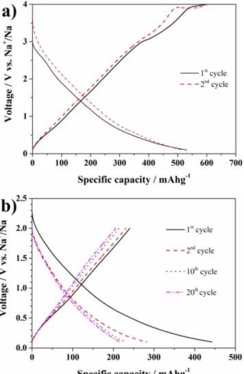
between 4.0 V and 0.1 V vs Na/Na+is reported in Figure2a. The discharge capacity at low cycling rate (C/10 or 14.7 mA g−1) exceeds 500 mAh g−1, corresponding to the insertion of more than 3.4 eq. of Na+. This value is among the highest reported so far for V2O5 -based electrodes (Table 1 in supplemental material),15–19,46 usually
investigated as cathodes and thus only in the voltage range of 4.0 V– 1.0 V (or 4.0 V–1.5 V) vs Na/Na+. However, between 1.0 V and 0.1 V
Figure 2. (a) Voltage profile of V2O5aerogel electrode upon the initial two
cycles at current density of 14.7 mA g−1(0.1 C) in the voltage range 0.1 V–4 V vs Na/Na+. (b) Selected voltage profiles of the V2O5electrode cycled at
C/10 in the voltage range 0.1 V–2 V vs Na/Na+
vs Na/Na+a capacity exceeding 300 mAh g−1(corresponding to 2 Eq. of Na+) is available, underlining the suitability of V2O5as potential anode material for SIBs. In addition, the sloping discharge potential profiles appear reversible in contrast to the report of Augustyn et al.,34
in which the Li+insertion into aerogel, or crystalline V2O5, was found associated with a remarkable first cycle irreversible capacity (probably due to electrolyte degradation). Therefore, these authors proposed the occurrence of a conversion mechanism occurring upon V2O5lithiation at low potentials, leading to the formation of VO and Li2O.34,47For many 3d-metal oxides, such reaction is generally accompanied by a plateau at around or below 1.0 V vs Na/Na+ (or vs Li/Li+).48This
plateau, however, is not present in the tests reported here, as indicated by the discharge profile in Fig.2a. Thus, it is reasonable to propose that the capacity in the whole potential range results only from Na intercalation, which is accompanied by the almost complete reduction of V5+to V3+(the theoretical capacity for the four electron process is about 588 mAh g−1).
During the following electrode desodiation (Fig.2a) some irre-versible process occurs at about 4.0 V vs Na/Na+, especially in the second cycle, which was not observed in our previous study in which a lower cutoff voltage of 1.5 V vs Na/Na+was applied.20The plateau
occurring at about 4.0 V vs Na/Na+might be related to a change of the surface chemistry favouring electrolyte decomposition. For such a reason, the upper cutoff was limited to 2.0 V and the obtained voltage profiles at C/10 are shown in Figure2b. Limiting the upper cutoff re-sulted in a delivered capacity of 250 mAh g−1during the first charge and 200 mAh g−1 in the subsequent cycles. The capacity contribu-tion arising from the sodiacontribu-tion of the Super C65 conductive carbon is, in the same voltage range, 75 mAh per g of carbon or 15 mAh per gram of composite electrode, clearly evidencing that the majority of the capacity is associated to the electrochemical reaction between Na and V2O5aerogel. Nevertheless, the comparison of the voltage vs capacity profiles in Figure2bshows as the aerogel-based electrode is affected by a continuous capacity fade as also observed in analo-gous Li+cells.20This behaviour is generally attributed to vanadium
ion dissolution49that, in case of the aerogel, is enhanced by the high
surface area.50Since surface coating techniques are not applicable as
often require annealing that would turn V2O5aerogel into the crys-talline form, we believe that a viable strategy to reduce the aerogel capacity fading could be the use of alternative electrolytes with in-situ SEI forming ability and/or reduced vanadium solubility. Further studies on this topic are currently ongoing in our laboratories.
The rate capability of the V2O5aerogel electrode was further eval-uate as shown in Figure S2 in the supplemental material. At 1C (147 mAg−1) and 2C (300 mAg−1) rates the discharge capacity is about 125 mAhg−1 and 77 mAh g−1, respectively. With a further increase of charge/discharge rate the capacity drops to very low values but recovering when lower rates of 1C are applied again.
To explore the behaviour of the aerogel at even lower voltages, the lower cutoff was step-wise lowered to 0.01 V vs Na/Na+, as shown in Figure 3a, while the upper cutoff limit was kept at 2 V
Figure 3. (a) Voltage profile of a V2O5 aerogel electrode obtained at
74 mAg−1(C/2) using progressively lower (the upper cut-off is fixed at 2 V vs Na/Na+). The inset shows the capacity delivered for each cycle at specific cutoff. (b) Long-term performance of V2O5aerogel electrode upon continuous
cycling at 100 mA g−1in the voltage range 0.01 V–1.5 V vs Na/Na+.
vs Na/Na+. The cell, cycled at C/2 (i.e., j= 74 mA g-1), displays a reversible capacity of 250 mAh g−1at almost every cutoff value (see inset). However, decreasing the potential cutoff has only a negligible influence on capacity.
The long-term cycling ability was tested at a current density of 100 mA g−1(about 0.7 C) between 1.5 V and 0.01 V vs Na/Na+as reported in Figure3b. This further reduced upper cut-off limit resulted in a somehow lower initial capacity (about 200 mAh g−1), but after 40 cycles a capacity value of 146 mAhg−1 was still achieved while the capacity retention from the 50th to the 200th cycles was about 68%. Although the fading issue needs to be further addressed, these preliminary results are promising, making worth the investigation of V2O5aerogel as anode material in full sodium-ion cells.
Carbon-coated Na3V2(PO4)3 was chosen as cathode material to demonstrate the feasibility of V2O5-based negative electrodes. The quality of the synthesized material was ascertained by XRD investi-gation. The differential plot, obtained by structural refinement of the collected XRD pattern is shown in Figure S3 in supplemental mate-rial. No peaks associated with crystalline impurities are present and no reflections corresponding to graphitic carbon are visible, meaning that carbon is mostly, if not totally, amorphous. The rhombohedral unit cell of Na3V2(PO4)3(space group R-3c) can be described as being com-posed of a network of VO6octahedron, each sharing corners with three PO4tetrahedrons. One Na-ion is located in one M1 (6b) site and, the other two, in the M2 (18e) site. The M1 sites are situated between two adjacent [V2(PO4)3] units in the same [V2(PO4)3]∞ribbon while M2 sites are located between adjacent [V2(PO4)3]∞ribbons, leading to a open 3D framework structure.12The lattice parameters resulted to be
Figure 4. C-coated Na3V2(PO4)3powder. (a-b) TEM and (c-d) SEM images,
at different magnification level.
a= b = 8.7278(9) Å, c = 21.8058(8)Å, and the unit cell volume 1438.5 (Å3), in good agreement with literature data.51From
thermo-gravimetric analysis (reported in Figure S4 in supplemental materials) the amount of carbon coating is estimated to be 5.4 wt%. TEM im-ages in Figures4a–4breveals that NVP/C is composed of particles of average size around 50 nm. The particles are well embedded and dispersed in a continuous porous carbon matrix, comparable with that reported by Wang et al.,52obtained from the decomposition of PAA
and D-(+) glucose. As shown in the SEM micrographs in Figures 4c–4d, the primary particles are merged together in large agglomer-ates surrounded by carbon. The carbon matrix enhances the electronic conductivity of the composite53while the porous structure is
benefi-cial for the Na+diffusion thanks to an higher contact area between the electrode and the electrolyte.54,55A constant current – constant
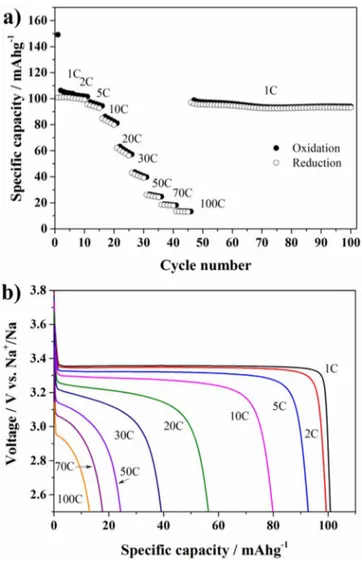
voltage (CC-CV) test was performed during charge of the cell at 1C up to 3.8 V vs Na/Na+. The latter potential was hold until the current decreased to a value of C/20. The subsequent discharging down to 2.5 V was performed at different rates (from 1C to 100C). The re-sults are shown in Figure5a. The composite cathode material showed good rate capability at medium C-rates, retaining more than 80% of the initial discharge capacity from 1 to 10C, delivering 100 and 82 mAh g−1respectively. By increasing the discharge rates the capac-ity decreases, however, the cell still delivers about 40 mAh g−1at 30C retaining 40% of the initial discharge capacity. The discharge voltage profile for the 5thcycle at each rate is reported in Figure5b. The char-acteristic flat voltage profile of Na3V2(PO4)3gradually shrinks with increasing cycling rate due to the intrinsic low electronic conductiv-ity and Na+-ion diffusion in the material (10−12to 10−15cm2s−1).56
When the cycling rate was brought back to 1C, the initial capacity was recovered almost completely (97 mAh g−1) proving that no sig-nificant active material deterioration occurred during cycling at very high current rates. On the other hand upon extensive cycling at 1C the capacity progressively decreases as also shown by the shrinkage of the voltage plateau at 3.4 V vs Na/Na+in the selected voltage profiles plot reported in Figure S5 in supplemental material. Nevertheless, the electrochemical performances of the carbon coated Na3V2(PO4)3are satisfactory for application in full SIBs.
The applicability of V2O5 aerogel as anode material in full sodium-ion cells was studied in combination with the carbon-coated
Figure 5. Electrochemical characterization of C-coated Na3V2(PO4)3. (a)
CC-CV test: while the charge is kept at 1 C the discharge rate is progres-sively increased up to 100 C (five cycle at each discharge rate was performed). Cut-off voltage: 3.8 V–2.5 V vs Na/Na+; the constant voltage period was kept until the current reached a value of C/20. (b) Discharge voltage profiles at different C-rates (the 5thcycle at each rate is reported).
Na3V2(PO4)3cathode. The anode was electrochemically pre-sodiated to compensate for the irreversible capacity occurring at the first cycle. The cell was subsequently cycled at current density of 100 mA g−1 (with respect to the weight of the anode). The cut-off voltages were set to 0.1 V–1.5 V vs Na/Na+and to 3.0 V–4.0 V vs Na/Na+for the anode and the cathode, respectively.
In a first attempt the cell was subjected to a pre-sodiation at a current density of 15 mAg−1 (Figure S6a in supplemental material). As reported in Figure S7 in supplemental material, during the first discharge the sodium-ion cell delivered 0.17 mAh, but the cell capac-ity continuously decreased upon cycling. Additionally the coulombic efficiency was unsatisfactory being lower than 90%.
In order to ameliorate the cell performance by reducing the ir-reversible capacity of the anode and improving the efficiency, a slower pre-sodiation was performed (Figure S6b in supplemental material) at current density of 3.7 mAg−1 (C/40). Indeed, the ini-tial anode capacity was 624 mAhg−1 (almost 300 mAh g−1 higher than that obtained using a higher current density) corresponding to the insertion of about 4.2 Eq. of Na+. The corresponding de-sodiation capacity is comparable to that of the faster pre-de-sodiation (about 122 mAh g−1). During subsequent cycling shown in Figure 6, the cell delivered less capacity than the one reported in Fig-ure S6 but the coulombic efficiency remarkably improves (>97%). The capacity progressively increased to a maximum of 0.135 mAh
Figure 6. Cycling performance of the V2O5aerogel/C-coated Na3V2(PO4)3
cell. The current density is 100 mA g−1(based on anode weight) and cut-offs set to 0.1 V–1.5 V and 3 V–4 V for the anode and the cathode respectively.
at the 28th cycle. Such value corresponds to 113.14 mAh g−1 and 60 mAhg−1 for the anode and the cathode, respectively. However, upon cycling the capacity faded constantly. After 150 cycles the cell capacity retention was only about 52% with respect to the maximum value obtained in the 28thcycle. The examination of the voltage pro-files in Figure7areveals that initially (i.e., from 1stto 28thcycle) the cell is charge limited by the anode reaching the cut-off of 0.1 V (i.e., before the cathode delivered its full capacity). The discharge, how-ever, is limited by the cathode reaching its lower cut-off limit. This is certainly associated with the initial irreversibility of the carbon-coated Na3V2(PO4)3also shown in Figure5a, which, however, is opposed to that of the anode. In practice, during the charge the cathode delivered to the anode a larger capacity than it could take back in the following discharge. However, in each following cycle the anode irreversibly consumed part of the Na+ ions available in the cell, allowing the cathode to deliver and take increasing capacities. The combination of these two irreversible but opposite processes led to a maximum in the cell capacity occurring at the 28thcycle. On continuous cycling, however, the cathode exhausted its capacity to provide Na+ ions to the cell, as indicated by the fact that the cathode hit its upper cutoff limit (see Figure7b). Thus, the continuous capacity fade of the anode resulted in the following cell performance decrease, in agreement with the half-and full-cell data reported above.
Nonetheless, the presented results are certainly encouraging. The cell performance, i.e., the cycling stability, can be further improved via the careful selection of electrolyte components and proper cell balancing.
Conclusions
Layered V2O5aerogel possesses appealing performance in terms of sodium ion uptake below 1 V vs Na/Na+. The ability to uptake the large Na+ ions may arise from the large interlayer space and short diffusion pathways characteristic of the aerogel morphology and structure. The overall electrochemical performance is satisfactory although the long-term cycling stability needs to be improved. In addition, deeper studies are necessary to clarify weather insertion is the main reaction mechanism. The suitability of V2O5 as negative electrode material for SIBs is also confirmed in full Na-ion cells using carbon coated Na3V2(PO4)3as positive electrode material. To the best of our knowledge the use of V2O5aerogel in full sodium ion battery has never been reported. This “proof of concept” cell relies only on vanadium redox couples, which is certainly advantageous with respect to cobalt- or nickel-based electrodes, when cost and abundance of raw materials are taken into account. Furthermore, the cell exhibits an average voltage of 2.5 V, which is higher than that of Ni-MH or vanadium redox flow batteries.
Figure 7. Selected anode and cathode voltage profiles recorded from the
sodium-ion cell reported in Figure6. The evolution of anode and cathode voltages during the capacity increase (up to the 28thcycle) is shown in panel
a). Panel b) illustrates the later cycles (up to the 200th).
Acknowledgments
This work was supported by BMBF within the project “MEET Hi-END - Materialien und Komponenten f¨ur Batterien mit hoher En-ergiedichte” (F¨orderkennzeichen: 03X4634A). The authors would like to thank IMERYS for providing material.
References
1. H. D. Yoo, I. Shterenberg, Y. Gofer, G. Gershinsky, N. Pour, and D. Aurbach,Energy & Environmental Science, 6, 2265 (2013).
2. M. M. Huie, D. C. Bock, E. S. Takeuchi, A. C. Marschilok, and K. J. Takeuchi,
Coordination Chemistry Reviews, 287, 15 (2015).
3. N. Jayaprakash, S. K. Das, and L. A. Archer,Chemical Communications, 47, 12610 (2011).
4. Q. Li and N. J. Bjerrum,Journal of Power Sources, 110, 1 (2002).
5. V. Palomares, P. Serras, I. Villaluenga, K. B. Hueso, J. Carretero-Gonzalez, and T. Rojo,Energy & Environmental Science, 5, 5884 (2012).
6. N. Yabuuchi, K. Kubota, M. Dahbi, and S. Komaba,Chemical Reviews, 114, 11636 (2014).
7. D. Buchholz, A. Moretti, R. Kloepsch, S. Nowak, V. Siozios, M. Winter, and S. Passerini,Chemistry of Materials, 25, 142 (2012).
8. S.-M. Oh, S.-T. Myung, J. Hassoun, B. Scrosati, and Y.-K. Sun,Electrochemistry Communications, 22, 149 (2012).
9. D. Buchholz, C. Vaalma, L. G. Chagas, and S. Passerini,Journal of Power Sources, 282, 581 (2015).
10. L. G. Chagas, D. Buchholz, C. Vaalma, L. Wu, and S. Passerini,Journal of Materials Chemistry A, 2, 20263 (2014).
20. A. Moretti, F. Maroni, I. Osada, F. Nobili, and S. Passerini,ChemElectroChem, 2, 529 (2015).
21. D. Buchholz, L. G. Chagas, C. Vaalma, L. Wu, and S. Passerini,Journal of Materials Chemistry A, 2, 13415 (2014).
22. S. Komaba, W. Murata, T. Ishikawa, N. Yabuuchi, T. Ozeki, T. Nakayama, A. Ogata, K. Gotoh, and K. Fujiwara,Advanced Functional Materials, 21, 3859 (2011). 23. D. A. Stevens and J. R. Dahn,Journal of the Electrochemical Society, 147, 1271
(2000).
24. P. Senguttuvan, G. Rousse, V. Seznec, J.-M. Tarascon, and M. Rosa Palacin, Chem-istry of Materials, 23, 4109 (2011).
25. H. Pan, X. Lu, X. Yu, Y.-S. Hu, H. Li, X.-Q. Yang, and L. Chen,Advanced Energy Materials, 3, 1186 (2013).
26. A. Rudola, K. Saravanan, C. W. Mason, and P. Balaya,Journal of Materials Chemistry A, 1, 2653 (2013).
27. L. Wu, D. Bresser, D. Buchholz, G. Giffin, C. R. Castro, A. Ochel, and S. Passerini,
Advanced Energy Materials, 5(2) (2015).
28. L. Wu, D. Bresser, D. Buchholz, and S. Passerini,Journal of The Electrochemical Society, 162, A3052 (2015).
29. A. Darwiche, C. Marino, M. T. Sougrati, B. Fraisse, L. Stievano, and L. Monconduit,
Journal of the American Chemical Society, 134, 20805 (2012).
30. D. Su, C. Wang, H. Ahn, and G. Wang,Physical Chemistry Chemical Physics, 15, 12543 (2013).
31. D. Bresser, F. Mueller, D. Buchholz, E. Paillard, and S. Passerini,Electrochimica Acta, 128, 163 (2014).
32. A. Darwiche, M. T. Sougrati, B. Fraisse, L. Stievano, and L. Monconduit, Electro-chemistry Communications, 32, 18 (2013).
33. L. Wu, X. Hu, J. Qian, F. Pei, F. Wu, R. Mao, X. Ai, H. Yang, and Y. Cao,Energy & Environmental Science, 7, 323 (2014).
34. V. Augustyn and B. Dunn,Electrochimica Acta, 88, 530 (2013). 35. H. Fei, Z. Li, W. Feng, and X. Liu,Dalton Transactions, 44, 146 (2015). 36. M. Secchiaroli, F. Nobili, R. Tossici, G. Giuli, and R. Marassi,Journal of Power
Sources, 275, 792 (2015).
37. A. C. Larson and R. B. Von Dreele, General Structure Analysis System (GSAS), Los
Alamos National Laboratory Report LAUR, 86-748 (2004).
38. I. Zatovsky,Acta Crystallographica Section E, 66, i12 (2010).
39. M. Giorgetti, S. Passerini, W. H. Smyrl, and M. Berrettoni,Inorganic Chemistry, 39, 1514 (2000).
40. V. Petkov, P. N. Trikalitis, E. S. Bozin, S. J. L. Billinge, T. Vogt, and M. G. Kanatzidis,
Journal of the American Chemical Society, 124, 10157 (2002).
41. O. Durupthy, N. Steunou, T. Coradin, J. Maquet, C. Bonhomme, and J. Livage,
Journal of Materials Chemistry, 15, 1090 (2005).
42. W. H. Smyrl, S. Passerini, M. Giorgetti, F. Coustier, M. M. Fay, and B. B. Owens,
Journal of Power Sources, 97–98, 469 (2001). 43. J. Livage,Chemistry of Materials, 3, 578 (1991).
44. S. Passerini, J. J. Ressler, D. B. Le, B. B. Owens, and W. H. Smyrl,Electrochimica Acta, 44, 2209 (1999).
45. F. Coustier, J.-M. Lee, S. Passerini, and W. H. Smyrl,Solid State Ionics, 116, 279 (1999).
46. D. Su, S. Dou, and G. Wang,ChemSusChem, 8, 2877 (2015).
47. E. C. Almeida, M. Abbate, and J. M. Rosolen,Solid State Ionics, 140, 241 (2001). 48. P. Poizot, S. Laruelle, S. Grugeon, and J.-M. Tarascon,Journal of The Electrochemical
Society, 149, A1212 (2002).
49. G. Sudant, E. Baudrin, B. Dunn, and J.-M. Tarascon,Journal of The Electrochemical Society, 151, A666 (2004).
50. B. B. Owens, S. Passerini, and W. H. Smyrl,Electrochimica Acta, 45, 215 (1999). 51. J. Liu, K. Tang, K. Song, P. A. van Aken, Y. Yu, and J. Maier,Nanoscale, 6, 5081
(2014).
52. Q. Wang, B. Zhao, S. Zhang, X. Gao, and C. Deng,Journal of Materials Chemistry A, 3, 7732 (2015).
53. Y. H. Jung, C. H. Lim, and D. K. Kim,Journal of Materials Chemistry A, 1, 11350 (2013).
54. J. Mao, C. Luo, T. Gao, X. Fan, and C. Wang,Journal of Materials Chemistry A, 3, 10378 (2015).
55. J. Kang, S. Baek, V. Mathew, J. Gim, J. Song, H. Park, E. Chae, A. K. Rai, and J. Kim,Journal of Materials Chemistry, 22, 20857 (2012).
56. S.-J. Lim, D.-W. Han, D.-H. Nam, K.-S. Hong, J.-Y. Eom, W.-H. Ryu, and H.-S. Kwon,Journal of Materials Chemistry A, 2, 19623 (2014).