SCHOOL OF DESIGN
MSc. in Design and Engineering
Master of Science Thesis
Compliant Mechanism in Passive Tremor
Suppression Glove for Parkinson’s Patients
Thesis Supervisor: Prof. Mario Guagliano
Co-supervisor: Dr. Stefano Monti
Author: Gautham Nambiar (891937)
Academic year 2018/2019
3
Acknowledgement
At the outset let me express my deep and respectful veneration to the supreme power we call ‘The Almighty’ for His abundant blessing and benevolence which I have been getting, especially since my sophomore year and that guided me to this level to reach the submission of my thesis successfully. I reverently hope that Omnipotent’s grace will continue to lead me in future too. I would like to express my sincere gratitude to several individuals, institutions, organizations and host of well-wishers for their unstinted support to make me what I am today. First and foremost, among them being my world renowned University Politecnico Di Milano, for not only accepting me to the ‘Masters Programme’ but also providing me with scholarship for almost couple of years, without which I doubt realization of my dream to reach this level would have been possible. I am deeply indebted to my esteemed Institution for all that they had provided me with, to prosecute my studies to a logical and successful conclusion.
I wish to express my heartfelt gratitude and sincere thanks to my co-supervisor Dr. Stefano Monti for his untiring enthusiasm, insightful and invaluable suggestions, sharing helpful information, practical advices and ideas which no doubt took me a long way at all levels in my writing this thesis. His deep knowledge, unfathomed professional expertise and his profound experience have enabled me to complete this Thesis successfully. I am highly indebted and grateful to my esteemed professor, Dr. Mario Guagliano for his precious time in guiding me and solving my queries patiently improving/correcting the flow of my Thesis, but for his unstinted cooperation, support and his sagacious guidance it would not have been possible for me to complete this Thesis in a time bound manner. Thanks a lot Sir, for your patience, kindness and forbearance especially for those many hours you had spent guiding with me. I will be ever grateful for all that you have gracefully done for my added value education.
I will be failing in my duties if I do not extend my sincere gratitude to all my Professors, Asst. Professors, Laboratory personnel and all other staff members who are so much dear to my heart, for rendering me with all additional knowledge and support. I would like to express deep and sincere thanks to the Dean and faculty members for providing valuable guidance throughout my
4
post-graduation period. Their dynamics, wisdom, vision, sincerity and motivation have deeply inspired me. I am indeed indebted to all for your love and care.
I am deeply grateful to my grandparents, Nanikutty Amma, Mr. K.V.G. Nair and Mrs. Roopa Nair, my beloved parents Mr. Krishnakumar and Mrs. Sreekala Krishnakumar and my brother Gaurav and all my uncles and aunts as also all my family members for their love, care and sacrifices, for my upbringing, educating and preparing a suitable ground for me to take a safe flight into my future.
Last but not the least, my special thanks and gratitude are due to my friends who have always been very kind and stood beside and motivated me in achieving my goal, but for their sincere support and encouragement it would have been next to impossible to have successfully completed my course to a logical conclusion. Thank you all.
6
ABSTRACT
Tremor is the most common movement disorder, affecting 5.6% of the population with Parkinson’s disease or essential tremor over the age of 65. Conventionally, tremor diseases like Parkinson’s are treated with medication. An alternative non-invasive symptom treatment is the mechanical suppression of the oscillation movement. In this thesis, the weaknesses of past wearable tremor-suppression orthoses for the upper limb has been identified and with the use of compliant mechanisms a unique and efficient solution to suppress this type of hand tremor has been designed and developed.
An Anti Tremor Glove is designed for the elderly and all those suffering from these diseases to ease their lifestyle. The glove consists of two principal parts one, is the compliant link connecting the hand to the forearm and two, the damping system on the forearm portion of the glove. Based on the research done in the field of tremors the only available data on tremor frequencies is of Parkinson’s patients. The damping system of the glove which works on the principle of friction requires the patient’s hand frequency, hand tremor velocities and acceleration. This glove is designed and engineered for people with Parkinson’s whose frequency of tremor ranges from low frequency values of 1.5 Hz to high frequency values up to 9 Hz. The Anti Tremor Glove can be tuned for higher frequencies which would make it a completely universal product which would suppress all tremor types when further research in this regard is done.
KEYWORDS: Compliant Mechanisms; Flexibility; Stiffness; Parkinson’s Disease;
7
ABSTRACT
Il tremore è il disturbo che colpisce il 5,6% della popolazione ed è tipicamente associato alla malattia di Parkinson oppore come tremore che si manifesta ad un’età superiore ai 65 anni. Convenzionalmente, le malattie come il Parkinson sono trattate con farmaci. Un trattamento sintomatico alternativo non invasivo è la soppressione meccanica del tremore. In questa tesi, sono state identificate le debolezze delle protesi indossabili per l'arto superiore presenti oggi sul mercato e viene presentata una soluzione innovativa che si avvantaggia dei cosiddetti compliant mechanisms.
In generale, un guanto anti-tremore è progettato per tutti coloro che soffrono di queste malattie per facilitare il loro stile di vita. Il guanto è costituito da due parti principali: la prima consiste nel collegamento tra mano e avambraccio, che sfrutterà l’elasticità offerta dal Compliant Mechanism; il secondo consiste in un sistema di smorzamento sulla parte dell'avambraccio. Sulla base della ricerca condotta, i soli dati disponibili sulle frequenze di tremore sono relativi ai pazienti con Parkinson. La frequenza del tremore varia in un range di frequenza da 1,5 Hz a 9 Hz. Il guanto anti-tremore può essere sintonizzato per frequenze più elevate che lo renderebbero un prodotto completamente universale che sopprimerebbe tutti i tipi di tremore quando si effettuano ulteriori ricerche in questo senso.
PAROLE CHIAVE: Meccanismi conformi; Flessibilità; rigidità; Morbo di Parkinson; Tremore
8
Table of Contents
Acknowledgement
3Abstract
6List of figures
11List of tables
14CHAPTER 1
1. Compliant mechanisms
151.1 What are compliant mechanisms? 15
1.2 Advantages of compliant mechanisms
17
1.3 Limitations of compliant mechanisms 18
1.4 Applications of compliant mechanisms
20
CHAPTER 2
2. Tremors
21 2.1 Definition21 2.2 Symptoms of tremor 21 2.3 Tremor classification 22 2.4 Tremor diagnoses
22 2.5 Pathophysiology of a tremor 23 2.6 Tremor frequency
24
2.7 Whom does it affect?
24
2.8 Available treatments 25
CHAPTER 3
3. Tremor suppression
263.1 Biomechanics of the upper limb
26
9
3.2.1 Products available
27
3.2.2 Benchmarking 30
3.2.3 Other non-commercial solutions
31
CHAPTER 4
4. Need for efficient orthotics
334.1 Existing product limitations 33
4.2 Future research
33
4.3 Required improvements
34
CHAPTER 5
5.
Proposed solution
355.1 What research suggests?
35
5.2 Product inspiration 35
5.2.1 Literature review
35
5.3 Design brief 40
5.4 Product ideation
41
CHAPTER 6
6. Anti Tremor Glove
426.1 Concept sketches
42
6.2 Components of the glove
44
6.2.1 The compliant links 44
6.2.2 The damping system 44
6.3 Working
45
CHAPTER 7
7. Material selection
477.1 Flexibility and stiffness
47
7.2 Material index 49
10
7.4 Material ranking for the damping system
51
CHAPTER 8
8. Determining the forces
538.1 Experimental data
53
8.2 Pull force and frictional force calculations 54
CHAPTER 9
9. CAE analysis
57CHAPTER 10
10. Manufacturing and cost analysis
7110.1 Epidemiology of tremor 71
10.2 Manufacturing process selection 71
10.3 Material costs
74
10.4 Overhead costs 76
CHAPTER 11
11. CAD model and prototype
77CHAPTER 12
12. Conclusion
84References
8711
List of figures
Figure 1: Examples of compliant mechanisms in nature 16
Figure 2: The bow and one of Leonardo da Vinci’s early designs have used compliant
mechanisms 17
Figure 3: Wright brother’s aircraft design used compliant wing warping to ensure a sustained
flight for humans 17
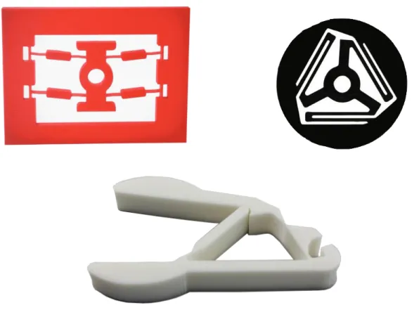
Figure 4: A bi-stable switch, a planar spring and a gripper these are examples of compliant
mechanisms 19
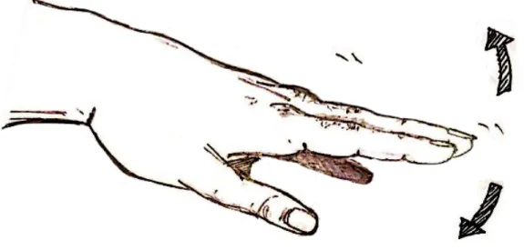
Figure 5: Sketch indicating the flexion and extension direction of the wrist 26
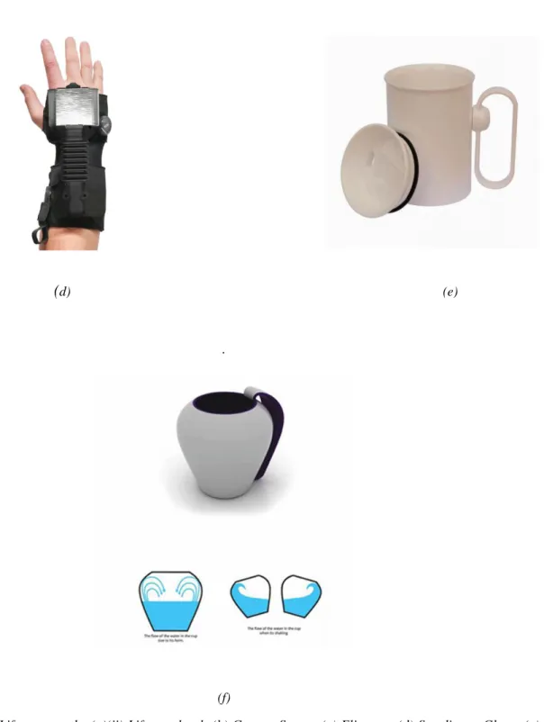
Figure 6: (a)(i) Liftware steady, (a)(ii) Liftware level; (b) Gyenno Spoon; (c) Elispoon; (d)
Steadiwear Glove; (e) Hand Steady Cup; (f) No spill cup 28
Figure 7: Prototype (a-c) and concept (d, e) orthoses. (a) WOTAS – active attenuator with electrical motor [35]; (b) Pneumatic Actuator – active attenuator with pneumatic piston-coil system [36]; (c) DVB Orthosis – semi-active attenuator using tuneable viscous shear resistance [37]; (d) Soft band Orthosis – semi-active attenuator using viscoelastic tendons [39]; (e) Piezoelectric Fibre Glove – active attenuator with piezoelectric fibre
composites [38] 30
Figure 8: (a) The First Embodiment with the direction of hand movement and forces Fc and Ft
acting on the link; (b) Position of the internal jaw during extension of the hand; (c) and position
during flexion of the hand 36
Figure 9: (a) Second Embodiment with the direction of hand movement; (b) Stretched out telescopic link in the extended position of the hand; (c)Contracted link in the flexed
position. 37
Figure 10: (a) Third Embodiment with the direction of hand movement; (b) extension of the hand
12
Figure 11: (a) isometric view of the new ball joint with grooves connected to the shaft; (b) Two
orthogonal views of the new ball joint. 39
Figure 12: Shows the fourth embodiment with a tuned mass damper setup on the forearm. Arrows show the direction of the hand and forearm movement. 39
Figure 13: The initial concept sketches that formed the basis of the final product 43
Figure 14: Shows the two compliant links with varying cross-section 44
Figure 15: Exploded view of parts 45
Figure 16: The cross-section of the damping system and its two extreme positions 46
Figure 17: The location of the mechanism on the arm within the glove and the complete glove worn by the user 46
Figure 18: A schematic representation showing the cantilever with the dimensions 47
Figure 19: Ashby chart showing the selected materials based on the constraints and the material index of 1 50
Figure 20: Examples of some common polypropylene medical products like syringes containers and foot orthosis 51
Figure 21: Examples of some household toys and enclosures made of ABS plastic. 52
Figure 22: Test positions to analyze (a) rest tremor and (b) position to analyze postural tremor 53
Figure 23: A simplified schematic representation of the glove mechanism 54
Figure 24: The initial compliant dual link design for analysis 57
Figure 25: The dual compliant link after assigning the material and properties 58
Figure 26: The dual compliant link with the applied Reference points, loads and boundary conditions 59
Figure 27: The meshed dual link for analysis 59
Figure 28: The von Mises stress result for 5N on the dual link 60
13
Figure 30: The compliant ridged link design for analysis 61
Figure 31: The ridged compliant link with the assigned material and properties 62
Figure 32: The ridged compliant link with the applied Reference points, loads and boundary conditions 62
Figure 33: The meshed ridged link for analysis 63
Figure 34: The von Mises stress result for 5N of the ridged link 63
Figure 35:The magnitude of displacement result for 5N of the ridged link 64
Figure 36: The new compliant link with smoothly varying cross-section for analysis 65
Figure 37: The new compliant link after assigning the material and properties 66
Figure 38:The part with the applied Reference points, loads and boundary conditions 66
Figure 39: The meshed part for analysis 67
Figure 40:The von Mises stress result for 5N 67
Figure 41:The magnitude of displacement result for 5N 68
Figure 42:The von Mises stress result for 10N 68
Figure 43: The magnitude of displacement result for 10N 69
Figure 44: The assembled mechanism and the arranged parts 77
Figure 45: Virtual 3D Printing tray and the positions of the parts that will be printed on the build-plate. 80
Figure 46: Layer by layer view shows the infill pattern and the main material in yellow and the support material in purple. 81
Figure 47: The 3d printed prototype parts and the assembled glove worn and two hand positions are shown. 82
14
List of tables
Table 1: Description of commercial products that adapt or suppress hand tremor 30 Table 2: Shows the acceleration angular velocity and frequency of the tremor in 10 different
patients 54
Table 3: PRIMA selection criterion chart 65
15
Chapter 1
1. Compliant mechanisms
1.1 What are compliant mechanisms?
A device or a machine that transforms input forces and movement into a desired set of output forces and movement is a mechanism. Generally, machines have mechanisms which contain parts that are arranged and move in a specific manner in order to obtain the desired output. Humans have been young machines since prehistoric times where we started with six simple machines like the axe, the ramp and so on these gave us a mechanical advantage and made certain tasks easier [1]. During the renaissance we saw some eminent scientists like Simon Stevin and Galileo Galilei work on dynamics and of mechanical powers and gave us laws that still hold relevant and have proved to be the foundation of mechanics [2]. We have come a long way from the simple machines to highly sophisticated modern machines that made life lot a lot easier. But what remains common is the basic types of mechanisms and movements that help these machines fulfil their purpose. These mechanisms are formed through assemblies of various rigid parts with multiple joints creating a system with controlled movements [3].
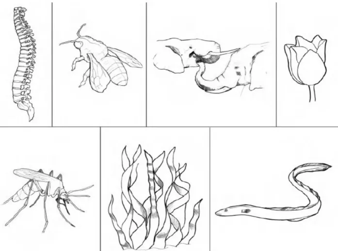
There is another type of mechanisms which gives us an entirely different idea, from rigid parts connected at joints. These mechanisms are a direct example of most moving things in nature which are very flexible and their motion is achieved by the bending of these flexible parts [4]. We can find many examples in nature like the trunk of an elephant, eels, seaweed, wings of a bee and the blooming of flowers. (figure 1)
If something bends and does what it is intended to do, then it is compliant. If this flexibility fulfils a particular purpose, then it can be called a compliant mechanism.
16
Figure 1: Examples of compliant mechanisms in nature
Even though compliant mechanisms existed in nature and around us since a very long time, designers tend to follow the traditional method of having stiff parts joined either with hinges or fasteners to create a moving machine. Now the use of compliant mechanisms is catching on and designers and engineers are incorporating compliance into new age human-designed products. It is rather ironical that the earliest of inventions show a much higher use of compliant mechanisms than in the present world. It could be because we were closer to nature then.
An interesting example of a compliant mechanism with a multi-millennia history is the bow (figure 2). Ancient bows were made using a composite of bone, wood, and tendon, and they used the flexibility of their limbs to store energy that would be released into propelling the arrow. It is interesting to see the sketches of Leonardo da Vinci [5] and see many compliant mechanisms (see figure 2 for an example).
17
Figure 2: The bow and one of Leonardo da Vinci’s early designs have used compliant mechanisms.
Even one of the great achievements of engineering – sustained human flight – began with a compliant mechanism when the Wright brothers (figure 3) used wing warping to achieve control of their early aircraft [6].
Figure 3: Wright brother’s aircraft design used compliant wing warping to ensure a sustained flight for humans
Now that we know what compliant mechanisms are, we can delve a little deeper into its uses, advantages, challenges etc. and understand more of its applications in today’s world.
1.2 Advantages of compliant mechanisms
Compliant mechanisms have compelling advantages over conventional mechanisms as many functions can be performed by minimal attachments. Due to this, the potential for lower costs of
18
parts is significantly high. Low costs are also because of reduced assembly, lesser components to stock and simplified manufacturing (such as fabricating a mechanism from a single mold). Compliant mechanisms give another advantage of optimum performance and high precision [7, 8] due to reduced wear and reduced or eliminated backlash. These mechanisms are low in weight and this makes it favorable for transportation and applications that are weight-sensitive. The need for lubrication at joints is inessential and this makes it a significant performance improvement that proves to be helpful for many applications in different environments. Another category of advantages lies in the ability to miniaturize compliant mechanisms. Microelectromechanical systems (MEMS) for example, are easily fabricated and produced from planar layers and compliant mechanisms offer a way to achieve motion with the extreme constraints caused by the resulting geometry [9, 10]. Compliant mechanisms are of paramount importance in the creation of nanoscale machines.
1.3 Limitations of compliant mechanisms
Even though the advantages of compliant mechanisms are impressive, they also have some challenges that must be carefully considered in their design. Just like how the integration of different functions into fewer parts offers advantages, it also requires a simultaneous design considering its motion and force behavior. This further becomes a challenge because of the fact that the deflections are mostly in the nonlinear range and the simplified linear equations are not useful to define or understand their motion. Since the motion of compliant mechanisms is based on bending of parts, stress is high at the bending areas, it is important to study fatigue life of compliant parts. During its life bending motion is repeated throughout and fatigue loads are developed, so the fatigue life of the mechanism must exceed its expected life. Fortunately, there are methods for analyzing and testing fatigue life which help design compliant mechanisms for their needed fatigue life, special attention and effort is required to ensure that the mechanism has the life required. No matter howwell designed and tested compliant mechanisms are and they may have the necessary fatigue life, but the consumer may a still perceive that such flexible components may be flimsy or weak. This is an important factor to consider if the flexible part is visible as it would require utmost care while designing for adequate fatigue life and its aesthetics. Compliant mechanisms have limited motion than the traditional rigid-link mechanisms. For example, a shaft with bearings can undergo complete revolutions but a flexible link mechanism can only undergo
19
a limited deflection before it fails. A deflected beam has strain energy stored in it that can be an advantage or disadvantage. The advantages being the fact that the flexible link or component can double up as a hinge and a spring and perform both the functions in a single component, which has a neutral position, where the component will go when unloaded. This gives rise to various behaviors like bistability (the characteristic of having two distinct preferred positions, such as the on-off positions of a light switch) [11].When such qualities are not desired in the device then it is a disadvantage to the system.Another challenge that compliant mechanisms have is that of stress relaxation. It is a phenomenon when certain materials are held under constant stress or loads or are exposed to high temperatures, then the part may take up a new shape associated to the stressed position. To overcome this,mindful design and discreet selection of material called for.
Figure 4: A bi-stable switch, a planar spring and a gripper these are examples of compliant mechanisms
20
1.4 Applications of compliant mechanisms
Technological developments and our recent advancements in studying of compliant mechanisms has led to a swift growth in compliant mechanisms application. High-end, high-precision devices to ultralow-cost packaging; from nanoscale featured components to large-scale machines; from weapons to healthcare products are some of the applications of compliant mechanisms. As mentioned earlier we know that many early devices were compliant mechanisms, but simplicity of analysis and design of rigid link mechanisms gave it an edge over the flexible link mechanisms during those times. In the present world there is a myriad of materials to choose from and are well suited for compliant mechanisms. There have been drastic improvements in the computational hardware and software that help analyze the motion and stresses of compliant mechanisms. Our ability to design and analyze compliant mechanisms have increased because of developers and researchers. Many new methods to facilitate compliant mechanism design have been created and considerable effort has been put in. Increased level of research and understanding has increased awareness of the advantages of compliant mechanisms. Some successful commercial applications prove to be an inspiration for other applications to follow suite. With all the advancements in society and technology, new needs have risen and compliant mechanisms prove to be useful to best address these needs. This includes products and devices with complex motion that are very small and need to be produced at relatively lower costs, concept tools (figure 4), compact medical implants and also high precision machines[12].
21
Chapter 2
2. Tremors
2.1 Definition
According to National Centre for Biotechnology Information (NCBI), a tremor is defined as a rhythmical, involuntary oscillatory movement of a body part that is produced by alternating contractions of reciprocally innervated muscles [13]. The underlying causes for hand tremors can be classified into Parkinson’s disease, essential tremors, multiple sclerosis, carpal tunnel syndrome, stroke, brain injury or a neurological disorder.
A tremor as defined generally, is an unintended and unplanned rhythmic movement of any part of the body. When hands shake or quiver it is in general known as ‘Tremor of the Hands’. There are many reasons for the origination of a tremor. The more frequent ones that we hear are that of neurological problems. But they can also be caused by metabolic problems.
Other causes are alcohol abuse or withdrawal syndrome, mercury poisoning, overactive thyroid or anxiety. In general, a tremor is originated by an issue in the deeper parts of the brain that control essential and important movements. Although some cases have underlying causes, certain cases are inherited and run in families.
2.2 Symptoms of tremor
Symptoms of tremor may include:
A rhythmic shaking of the hands, arms, head, legs, or torso, shaky voice, difficulty in writing or drawing, problems in holding and controlling utillities such as a cup, spoon, fork etc.
Some tremor may be triggered by or become worse during times of stress or strong emotion, when an individual is physically weared, or when a person is in certain postures or makes certain movements [14].
22
2.3 Tremor classification
Resting tremor occurs when the muscle is relaxed, such as when the hands are rested on the lap. With this disorder, a person’s hands, arms, or legs may shake even when they are at rest. Often, the tremor only affects the hand or fingers. This type of tremor is often seen in people with Parkinson’s disease and is called a “pill-rolling” tremor because the circular finger and hand movements resemble rolling of small objects or pills in the hand [14].
Action tremor occurs with the voluntary movement of a muscle. Most types of tremor are considered action tremor. There are several sub-classifications of action tremor, many of which overlap [14].
• Postural tremor occurs when a person maintains a position against gravity, such as holding the arms outstretched.
• Kinetic tremor is associated with any voluntary movement, such as moving the wrists up and down or closing and opening the eyes.
• Intention tremor is produced with purposeful movement toward a target, such as lifting a finger to touch the nose. Typically, the tremor will become worse as an individual gets closer to their target.
• Task-specific tremor only appears when performing highly skilled, goal-oriented tasks such as handwriting or speaking.
• Isometric tremor occurs during a voluntary muscle contraction that is not accompanied by any movement such as holding a heavy book or a dumbbell in one position for long [14].
2.4 Tremor diagnoses
Tremor is diagnosed based on a physical and neurological examination and an individual’s medical history. During the physical evaluation, a doctor will assess the tremor based on:
• whether the tremor occurs when the muscles are at rest or in action
• the location of the tremor on the body (and if it occurs on one or both sides of the body)
23
The doctor will also check other neurological findings such as impaired balance, speech abnormalities, or increased muscle stiffness. Blood or urine tests can rule out metabolic causes such as thyroid malfunction and certain medications that can cause tremor. These tests may also help to identify contributing causes such as drug interactions, chronic alcoholism, or other conditions or diseases. Diagnostic imaging may help determine if the tremor is the result of damage in the brain [13].
Additional investigative tests may be conducted to determine functional limitations such as difficulty with handwriting or the ability to hold a fork or cup. Individuals may be asked to perform a series of tasks or exercises such as placing a finger on the tip of their nose or drawing a spiral.
The doctor may order an electromyogram to diagnose muscle or nerve debilities. This test measures involuntary muscle activity and muscle response to nerve stimulation [13].
2.5 Pathophysiology of a tremor
Progress has been achieved in mapping tremors to certain structures or pathways in the nervous system, even though the exact pathophysiology of tremor is still incompletely understood. Two basic principles have been postulated in tremorogenesis. Tremorogenesis emphasizes:
i) Hyperexcitability and rhythmic oscillation of neuronal loops in the absence of structural changes. This ‘hyperexcitability’ has been studied with neurophysiologic techniques in humans and animals, modelled in dynamic mathematical paradigms. Complete reversibility of some tremor symptoms after alcohol ingestion or with medication has been interpreted as evidence for an overwhelmingly or exclusively functional disturbance.
ii) The second principle is that of a permanent structural pathology with signs of neurodegeneration. This concept has more recently received renewed attention after systematic pathologic studies of patients with essential tremor revealed characteristic pathologic change [13]
24
2.6 Tremor frequency
The Spectral analysis of hand tremor records obtained from normal subjects during continuous extension of the hand for 15–45 minutes, revealed that the root-mean-square (rms) displacement amplitude of the tremor increased from control levels of about 30 mum to levels on the order of 100–1,000 times control [15]. Associated with this increase in the displacement was a systematic decrease in the hand tremor frequency from control values of 8–9 Hz to values of 4–6 Hz [15]. Spectral analysis of demodulated extensor EMG records indicated a consistent relation between EMG modulation amplitude at the tremor frequency and the tremor displacement amplitude for tremor records with rms displacement above about 100 mum [15]. No consistent relation was found between these two variables for tremor records with displacements below 100 mum. Consideration of both mechanical and neural reflex effects indicated that a viscoelastic-mass mechanism primarily determined the small-amplitude (less than 100 mum) tremors, while the large displacement tremors may have involved both mechanical and neural feedback factors [15].
2.7 Whom does it affect?
Tremor is a rhythmic, involuntary, oscillatory movement of a limb produced by alternating contractions of reciprocally innervated muscles. More than 4% of the population over 40 years old suffer from tremor. Tremor is a major symptom of Parkinson’s disease (PD) that affects 80% of PD patients [16]. PD tremor is usually a rest tremor at the range of 3.5 to 6 Hz and can appear as pill-rolling, supination/pronation or flexion/extension movement of the forearm [17].
Parkinson’s disease (PD) is characterized by its main motor symptoms bradykinesia, rigidity and tremor, but also have additional motor and non-motor characteristics. The onset of the disease is usually at an age of 65 to 70 years. Onset before the age of 40 is seen in less than 5% of the cases in population-based cohorts. Earlier onset is seen in genetic variants. Monogenetic forms of PD are probably rare in unselected populations but may be frequent in some ethnic groups. In general, genetic factors are thought to be involved in 5–10% of the cases, may be more. The disease is slightly more frequent in men than women. The prevalence of the disease is generally accepted to range from 100 to 200 per 100,000 people and the annual incidence is thought to be 15 per 100,000. Research on whether there is increasing occurrence of the disease, exceeding what can be expected in an ageing population is ongoing [18].
25
2.8 Available treatments
The exact cause of ET and PD is unknown [19, 20]. Neither of these diseases is curable and the treatment is focused on relieving the symptoms [21]. The most used treatment for tremor is medication, although up to 53% of people discontinue medical treatment due to side-effects or lack of efficacy [22, 23]. Several surgical options for tremor treatment exist, including radiofrequency lesioning and gamma knife radiosurgery. Deep brain stimulation (DBS) as a surgical procedure is the most effective treatment for most tremors and is applied for advanced and selected cases [24]. Deep brain stimulation is, however, an invasive treatment with the potential for adverse events, such as cognitive, psychiatric and behavioral status change, that affect up to 48% of the people undergoing the surgery [25]. The tremor reduction efficacy of medication ranges from 23 to 59% for PD [26] and 39 to 68% for ET patients, whereas DBS has a tremor reduction of 90% [24]. In the study by Koller et al., 16% of the patients had a loss of efficacy of the DBS within 40 months [27]. Although there is a lack of long-term pharmacological studies [27], Sasso et al. showed that the Primidone tremorolytic effect only lasts for up to 1 year [28]. A new emerging surgical treatment of tremor is high intensity focused ultrasound. A recent study showed that this less-invasive method reduced the tremor score by 55% after 6 months, which is also related with mild to moderate adverse events [29]. More precisely, 74 neurological adverse events in 56 patients were observed, while an alteration in sensation was the most common one in 38% and persisted at 12 months in 14% [30]. Alternative treatments are required for patients not responding to medication (50% of ET), who are drug intolerant or are not suitable for deep brain stimulation [31]. Due to these side effects and the lack of efficacy, there remains a need for non-invasive treatments. Even with optimal medical or surgical intervention in tremor, patients will still require physical interventions and occupational therapy to promote social participation [32]. Adding weight to the limb, limb cooling, vibration therapy, transcranial magnetic stimulation, sensory electrical stimulation, and functional electrical stimulation are current alternative and supplementary treatments of tremor [22]. An emerging alternative and supplementary treatment are the physical intervention and suppression of the occurring oscillating rhythmic movement with a wearable external orthosis.
26
Chapter 3
3. Tremor suppression
3.1 Biomechanics of the upper limb
An understanding of the biomechanics is necessary to define the necessary specification of a wearable tremor suppression device. It is essential for the degrees of freedom (DOF) in the anatomy of the upper limb for wearable devices to match the inherent mobility of the limb and avoid inhibiting the movement of the user. Not considering the DOF in the hand, the arm has 7 DOF from wrist to shoulder: flexion and extension (figure 5) (WFE), and radial and ulnar deviation in the wrist (WD), pronation and supination in the forearm (FPS), flexion and extension in the elbow, and flexion and extension, abduction and adduction as well as internal and external rotation in the shoulder [33]. Besides the biomechanics of the upper limb, it remains essential that the location of ligaments, blood vessels, nerves, and tendons is considered in the design of a wearable device to prevent unintentional harm. The kinematics of the arm and thereby those of tremor, like joint inertia and joint stiffness, are changed by a wearable assistive device, for example by its weight. Furthermore, the physical suppression of tremor can cause a shift of tremor from the suppressed distal joint to a proximal joint (defined as the Distal to Proximal Tremor Shift phenomenon), observed in one out of six patients in the study by Manto et al. in 2007 [34].
27
3.2 Tremor suppression solutions
There are a wide range of products and concepts in the market that suppress or adapt to hand tremor. Some of the types of tremor suppression solutions available are as follows
• Wearable orthosis/ exoskeletons. • Handheld devices
• Table mounted device
• Medication
• Invasive and surgical methods
From the above mentioned, the most effective solutions are the supplementary and noninvasive treatment methods using wearable orthosis and other handheld or table mounted devices.
3.2.1 Products available
(a)(i) (a)(ii)
28
(d) (e)
.
(f)
Figure 6: (a)(i) Liftware steady, (a)(ii) Liftware level; (b) Gyenno Spoon; (c) Elispoon; (d) Steadiwear Glove; (e) Hand Steady Cup; (f) No spill cup
The above products in figure 6 are commercially available and have been used by people suffering from tremors. From the above products the most of them are tremor adaptive and do not play any role in minimizing the user’s tremor, except for the Steadiwear Glove, which is a passive tremor
29
suppressing orthotic glove. The others are mainly handheld devices that aid the user for a specific task. Whereas the glove can be worn by the user to perform any activity without worrying about the tremor. The benchmarking of these products will give us a better insight on the characteristics of a tremor suppressing device.
30
3.2.2 Benchmarking
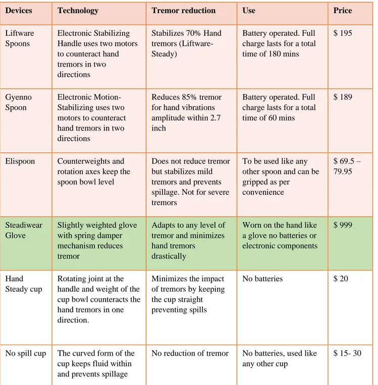
Devices Technology Tremor reduction Use Price
Liftware Spoons
Electronic Stabilizing Handle uses two motors to counteract hand tremors in two directions Stabilizes 70% Hand tremors (Liftware-Steady)
Battery operated. Full charge lasts for a total time of 180 mins
$ 195
Gyenno Spoon
Electronic Motion-Stabilizing uses two motors to counteract hand tremors in two directions
Reduces 85% tremor for hand vibrations amplitude within 2.7 inch
Battery operated. Full charge lasts for a total time of 60 mins
$ 189
Elispoon Counterweights and rotation axes keep the spoon bowl level
Does not reduce tremor but stabilizes mild tremors and prevents spillage. Not for severe tremors
To be used like any other spoon and can be gripped as per convenience $ 69.5 – 79.95 Steadiwear Glove
Slightly weighted glove with spring damper mechanism reduces tremor
Adapts to any level of tremor and minimizes hand tremors
drastically
Worn on the hand like a glove no batteries or electronic components
$ 999
Hand Steady cup
Rotating joint at the handle and weight of the cup bowl counteracts the hand tremors in one direction.
Minimizes the impact of tremors by keeping the cup straight preventing spills
No batteries $ 20
No spill cup The curved form of the cup keeps fluid within and prevents spillage
No reduction of tremor No batteries, used like any other cup
$ 15- 30
31
3.2.3 Other non-commercial solutions
Apart from the earlier mentioned commercial products there are many other concepts and prototypes that address the problem of suppressing hand tremor or upper limb tremor using various active and passive mechanisms. The following figure 7 shows some of the prototypes of tremor suppression orthosis.
Figure 7: Prototype (a-c) and concept (d, e) orthoses. (a) WOTAS –active attenuator with electrical motor [35]; (b) Pneumatic Actuator –active attenuator with pneumatic piston-coil system [36]; (c) DVB Orthosis –semi-active
attenuator using tuneable viscous shear resistance [37]; (d) Soft band Orthosis –semi-active attenuator using viscoelastic tendons [39]; (e) Piezoelectric Fibre Glove – active attenuator with piezoelectric fibre composites [38].
A concept is defined as a theoretical design not exceeding the model validation in the development process, whereas a prototype is defined as a functional device with the possibility to validate and evaluate its properties.
The orthoses are classified by its type of vibration suppression: passive, semi-active and active. Semi-active and passive technologies suppress involuntary movements, whereas active technologies suppress involuntary while supporting voluntary motions of the wearer’s limb. More specifically, passive suppression comprises robust methods regarding the design which ae dependent on constants like a spring and damper coefficient. A passive spring-damper system has a low resistance force at low and a high resistance at high velocities. Slow and deliberate movements can be accomplished, whereas fast movements create a higher reaction force.
Semi-32
active orthoses work like passive orthoses but use tunable mechanism characteristics regulated by a controller. An active orthosis reacts to sensory information with an actuator. An equally strong, oppositely directed force is used to counteract the involuntary movement [40].
33
Chapter 4
4. Need for efficient orthotics
4.1 Existing product limitations
Most of the prototypes did not reach the market due to their low wearability, leading to a lack of acceptance by the user. Wearability is the comfort and ergonomics in contrast to the performance. The high weight and the rigid structures lead to low ergonomics and comfort. Especially elder patients are more sensitive to weight due to sarcopenia, the degenerative loss of skeletal muscle mass associated with aging. power sources such as batteries may be relatively heavy and may need to be recharged frequently and replaced periodically. Such limitations may make devices implementing active force feedback systems less convenient to use and more expensive to buy and maintain. Also, active systems may be sensitive to water, magnetic fields, temperature changes, and shocks that may result when a user accidentally drops or hits the device against a hard surface. Furthermore, older people often have a negative attitude towards technology, especially towards gerontechnology [41]; therefore, a high wearability and an unobtrusive design are required improvements.
4.2 Future research
In order to develop appropriate tremor-suppression orthoses, the biomechanics of the tremorous movement need to be characterized, as proposed by Charles et al. [42]. Further investigations for the human-machine interface are needed, to improve the connection of a wearable device to the human body with an ideal force transmission. For this, an improvement in the understanding of tremorous movements and influencing factors of soft tissues are crucial. Future research probably needs to focus on soft suppression mechanisms with improved efficacy for tremor suppression to attain higher rates of patient acceptance. To this end, a future orthosis needs to be less obtrusive and more visually appealing, as well as to incorporate more biomimetic design features, inspired by nature’s functions and mechanisms [40].
34
4.3 Required improvements
This higher patient acceptance combined with improved efficacy could be achieved by the improved wearability along with such soft mechanisms and the new possibilities of an unobtrusive design. A new orthosis with a soft suppression system and improved suppression efficacy needs to have enough variability to accommodate all patients and different tremor types. Such an orthosis could be used in future to investigate the effect of such tremor suppression orthosis on the subject and its involuntary movement in short- and long-term use, like the distal to proximal tremor shift phenomenon. This higher patient acceptance combined with improved efficacy could be achieved by the improved wearability along with such soft mechanisms and the new possibilities of an unobtrusive design. A new orthosis with a soft suppression system and improved suppression efficacy needs to have enough variability to accommodate all patients and different tremor types [40].
35
Chapter 5
5. Proposed solution
5.1 What research suggests?
From the present research and market analysis of the products we can understand that an optimal tremor-cancelling orthotic glove must be:
• Soft
• Non-cumbersome • Compact
• Powerful • Lightweight
• Passive suppression system
Soft mechanisms show a high potential for wearable devices, as they are less bulky and especially visually more appealing. Current users of conventional rigid robotic orthoses claim that these are too bulky, which can lead to negative effects in activities of daily living or in the worst case to social exclusion [43]. Veale et al. propose to direct research towards compliant mechanisms in orthoses [44].
5.2 Product Inspiration
5.2.1 Literature review
The Steadiwear Glove:
This product is an apparatus that dampens the involuntary vibration or movement of the hand and the forearm of a person generally suffering from Parkinson’s or Essential tremor. This patent consists of many embodiments of the product but, each one of the embodiments work with the same principle and serve the same purpose of dampening the vibrations of the hand and forearm. The product has mainly two parts the first being a system that dampens the involuntary hand and forearm motion. This system is connected to the hand with a link. There are a few embodiments of this product before the final one. Each of the embodiments has an improvement from its former embodiment [45].
36 First Embodiment:
(a)
(b) (c)
Figure 8: (a) The First Embodiment with the direction of hand movement and forces Fc and Ft acting on the link; (b) Position of the internal jaw during extension of the hand; (c) and position during flexion of the hand.
In the first embodiment, figure 8(a), the damping system shown is a rectangular chamber filled with Non-Newtonian fluid and it also contains a movable jaw that is connected by a link that extends out of the box through a port and is fixed to the hand. Similarly, there is another unit on the underside of the arm, in which the link extends from the palm to the second rectangular chamber on the underside of the forearm (not shown in the figure). This embodiment helps minimize the hand tremor in two directions. The first direction being extension of the hand and the second being the flexion of the hand. During extension as shown in figure 8(b), the link on the
37
upper side of the hand is being pulled downwards which in turn pulls the jaw within the fluid filled chamber and as the fluid passes through the holes in the jaw (not shown) it offers resistance to the jaw and reduces the involuntary motion of the hand in that direction. During Flexion the same happens to the unit on the underside of the hand and it offers resistance, meanwhile the jaw in the unit on the upper part of the goes to its end position with help of the springs and it offers no resistance as fluid flows easily through a non-return valve in the jaw. So, the upper unit dampens the hand motion during extension and the bottom unit dampens the hand motion during flexion. The damping that is achieved is mainly as a result of the Non-Newtonian fluid which is present in it. The fluid has certain characteristics and is tuned in a way that it dampens only the involuntary motion of the user’s hand. Its performance is optimized to dampen tremors within the frequency range of 2 to 12 Hz [45].
Second Embodiment:
(a)
(b) (c)
Figure 9: (a) Second Embodiment with the direction of hand movement; (b) Stretched out telescopic link in the extended position of the hand; (c)Contracted link in the flexed position.
38
The second embodiment eliminates the use of two chambers as in the first embodiment. As shown in figure 9(a), a spherical chamber with a ball joint is used. This forms the damping system which is secured on the forearm. The ball joint is connected to the hand by a telescopic link. So as the hand extends the link will stretch out and as the hand flexes the link will contract (as shown in figure 9(b, c)). As the hand moves, the ball joint also moves within the spherical chamber. The damping is achieved by the Non-Newtonian fluid which is filled in a small gap between the ball joint and the spherical chamber. As the ball rotates or moves within the spherical chamber the Non-Newtonian fluid offers resistance and dampens the vibration. The ball joint connection dampens the tremor in the radial and ulnar directions of hand movement as well [45].
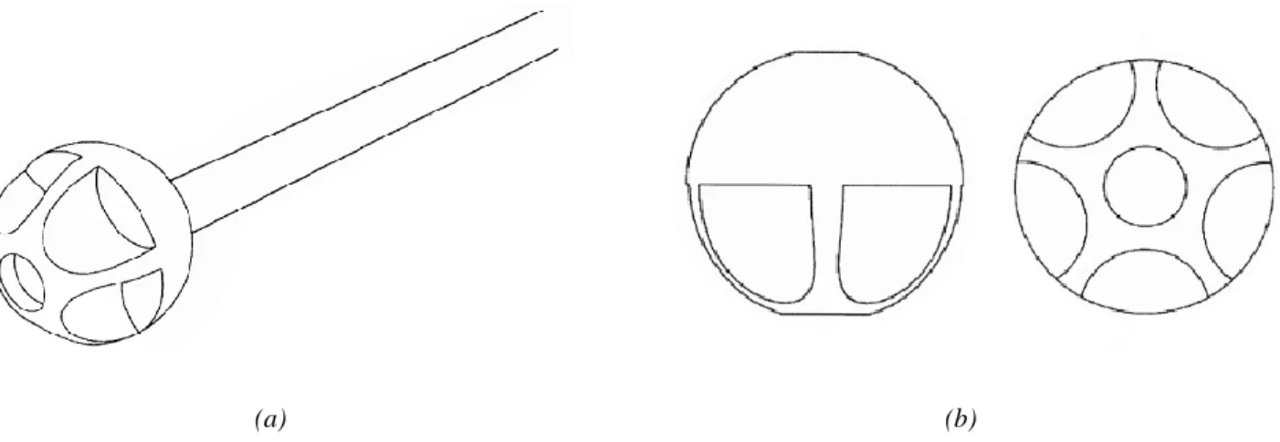
Third Embodiment:
(a)
(b) (c)
Figure 10: (a) Third Embodiment with the direction of hand movement; (b) extension of the hand (c) flexed position of the hand
39
The third embodiment as in figure 10, is just slightly different from the earlier. The telescopic link has been replaced by a shaft and a linear bearing is introduced at the portion of the hand. Also, the ball joint has a few added groves in it as shown in figure 11 (a, b). This accommodates more Non-Newtonian fluid in the chamber and helps resist the tremors more efficiently by generating more shear friction [45].
(a) (b)
Figure 11: (a) isometric view of the new ball joint with grooves connected to the shaft; (b) Two orthogonal views of the new ball joint.
Fourth Embodiment:
Figure 12: Shows the fourth embodiment with a tuned mass damper setup on the forearm. Arrows show the direction of the hand and forearm movement.
In this the parts and the design of the third embodiment remains as it is. Along with the previous setup there is an additional unit attached on the forearm which dampens the involuntary forearm movements. A tuned mass damper is used to achieve this, as shown in in figure 12 [45].
40
5.3 Design Brief
Use of compliant mechanism to damp tremor.
Universal design to adapt to wide a range of frequencies and cater to a vast demographic.
Portable product for easy accessibility and use.
No batteries.
Simple and passive systems, No electronic components
41
5.4 Product ideation.
With the research data and the design brief, a solution to suppress tremor can be devised. The idea is to effectively tackle this problem is by designing and engineering a novel glove which would suppress the involuntary hand tremors without any hassle of having bulky electronics and heavy batteries. So, the new glove will have a compliant link, from the literature review is clear that the link in the Steadiwear glove being a rigid shaft inhibits the full range of hand motion and offers slight resistance to voluntary hand movements of the user. Also, the existing prototypes of the exoskeletons have not been successful due to their low wearability (figure 7). Replacing the link with compliant mechanism will give the opportunity to build a compact, ergonomic and efficient glove unlike any other.
The hand tremor will be suppressed by utilizing the principle of friction, the damping system of the new glove would use sliding friction to offer resistance which otherwise in the Steadiwear glove was shear resistance generated by the Non-Newtonian fluid. Use of fluids increase maintenance costs as well as it poses a hazard to the user if there occurs a leak in the glove over a long period of its use.
The Anti Tremor Glove will be an affordable, easy to use, universal and completely portable product for the masses. It aims to help the old or young people alike, with which victims of hand tremor can continue to do their daily tasks independently with ease just like normal individuals.
42
Chapter 6
6. Anti Tremor Glove
From the product ideation phase comes the concepts of the glove its design and how the final solution is visualized.
43
44
6.2 Components of the Glove
The Glove consists of two main components 1. The Compliant Links
2. Damping system.
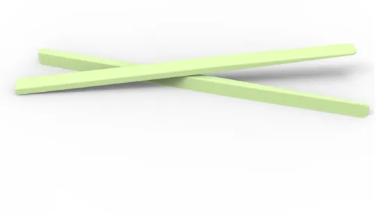
6.2.1 The Compliant Links
The compliant links are responsible for the bending and act as sliders that moves in tandem with the user’s hand (figure 14). These links are responsible to transfer the tremor motion from the hand to the damping system. These links must perform both functions of flexibility and stiffness for the
Figure 14: Shows the two compliant links with varying cross-section.
proper transfer of motion. The smaller cross-section of the link will be undergoing deflections with the hand as it bends and moves due to the involuntary tremor movements.
6.2.2 The Damping System
As the name suggests this component is responsible for the suppression of the involuntary hand movements. As the compliant links help to translate the hand motion the damping system is
45
responsible to apply resistance to the motion of the link which in-turn restricts the hand movements.
The damping system consists of six parts which are, the base, the rubber pads, the jaw, the top cover and for the adjustable mechanism there is a socket head screw and a spring (as in figure 15).
Figure 15: Exploded view of parts
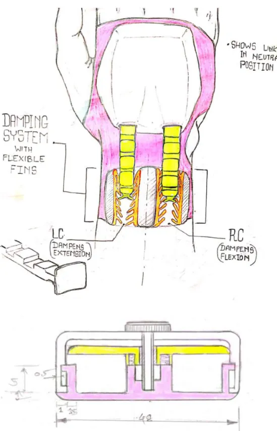
6.3 Working
The compliant links passes through the two spaces, over the two rubber pads that are bonded on to the base of the system. Then over it comes the jaw, which also has the rubber pads attached to it, thus the link is sandwiched between the rubber pads on the base and the jaw of the damping system. These pads can be moved closer to each other with the help of the socket head screw which moves the jaw and the rubber pads exert compressive forces on the links which increases the resistance enough to suppress the tremors of different frequencies. The spring keeps the jaw in place and keeps it attached to the socket head screw so that it can move up and down as and when the screwed is loosened or tightened based on the user’s need. The adjustable mechanism allows the user to adjust position of the jaw based on the amount of resistance required which depends on the severity or mildness of the tremor. Figure 16 shows the two positions, the first one being the open position, in which the links are free since the jaw is in its topmost position. As the screw is
46
tightened the jaw is lowered and it compresses the two links as shown in the second position. This is how the tremor suppression takes place. Since the compressive forces can be adjusted with the help of the screw it is calibrated such that it only can offer resistance to the involuntary forces generated in the hand and hence the voluntary movements of the user will not be affected. The proposed aesthetic of the glove and the location of the mechanism on the users arm is shown below (figure 17).
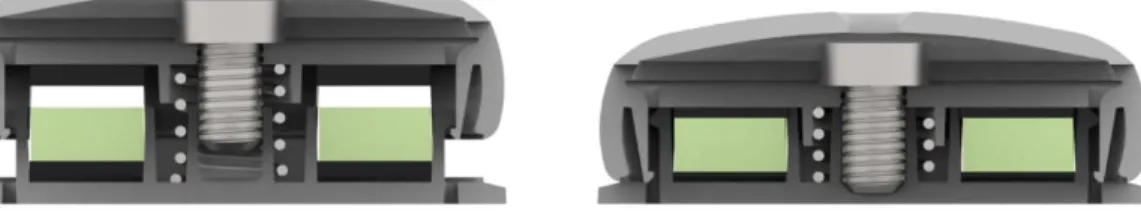
Figure 16: The cross-section of the damping system and its two extreme positions.
47
Chapter 7
7. Material Selection
7.1 Flexibility and Stiffness
For the compliant connecting link Objectives
• Withstand forces that cause bending i.e. bending stresses. • Undergo significant deflection without yielding.
• The link should deflect upto 140mm and not fail.
• Resist wear and should be resistant against fluids like water, dust, household chemicals etc. Considering the link connecting the hand and the damping system to be a cantilever beam of the following dimensions and cross-section (figure18).
48
For a cantilever of rectangular cross-section, we analyze the stiffness and the strength. Deflection of the above cantilever beam acted upon by a load F is given by
𝛿 = 𝐹𝐿3
3𝐸𝐼 1
And the moment of Inertia I for a beam of rectangular cross-section is, 𝐼 =𝑏ℎ3
12 2
∴ The stress due to bending is given by,
𝜎 =𝑀𝑦
𝐼 3
Where:
M= moment load
y= distance between neutral axis and point of interest. I= moment of inertia of cross-section.
The maximum stress at will be at the farthest point from the neural axis,
𝑦𝑚𝑎𝑥 = 𝑐 4
∴ 𝜎𝑚𝑎𝑥 =𝑀𝑐
𝐼 5
It is useful to analyze the system with maximum stress if the beam had a known force or load. Since, we need a compliant system that should be flexible enough to accommodate a certain amount of deflection the boundary conditions of our beam will change from a point load or force and the input will be a displacement load.
So, from equation 1and 2 we have,
𝛿 = 4𝐹𝐿3
𝐸𝑏ℎ3 6
Now from equation 5 we know that 𝜎𝑚𝑎𝑥 occurs at 𝑦𝑚𝑎𝑥 = 𝑐, so in our case,
𝑀𝑚𝑎𝑥 = 𝐹𝐿 and 𝑐 = ℎ 2
49
𝜎𝑚𝑎𝑥 = 6𝐹𝐿
𝑏ℎ2 7
Let us assume the failure of the beam occurs when the maximum stress equals yield strength, Sy
∴ 𝑆𝑦 = 6𝐹𝐿
𝑏ℎ2 (at failure) 8
Rearranging and solving for F we get,
𝐹 =𝑆𝑦𝑏ℎ2
6𝐿 9
Now substituting equation 9 in equation 6 the max deflection that the beam will undergo before failure is given as:
𝛿𝑚𝑎𝑥 = 2 3 𝑆𝑦 𝐸 𝐿2 ℎ 10
Therefore, the maximum deflection depends on both geometry (𝐿
2
ℎ) and material properties ( 𝑆𝑦
𝐸).
7.2 Material Index
To select the material based on the constraints, in equation 10 we need to maximize 𝛿 by minimizing 𝑆𝑦
𝐸
∴ The material index can be selected as follows, 𝛿𝑚𝑎𝑥= 𝑆𝑦
𝐸 which can be maximized by minimizing E and maximizing Sy
∴ log 𝛿 = log 𝑆𝑦− log 𝐸
50
On the Ashby charts we rank materials on a slope of 1 (m=1), hence the material index for selecting materials using Ashby charts is Mt = 1 (figure 19).
Figure 19: Ashby chart showing the selected materials based on the constraints and the material index of 1.
7.3 Material Ranking for the Compliant Links
The material to be selected must be durable against fresh water, salty water also strong acids and other fluids and must be easily cleanable also it must have acceptable resistance against sunlight and must withstand outdoor weather conditions to a certain extent.
Polypropylene (PP) is material that fulfils the given limits and is optimum material that has the best stiffness and flexibility without compromising on the strength, which is a necessary aspect in this application.
51
Polypropylene plastic helps accommodate for large deflections for the efficient functioning of the tremor suppression device. Also, the geometry of the component is of varying cross-section since the component needs to be stiff and flexible. Metals can be used for this application too. But, the amount of deflection required is large and since metals have higher Youngs modulus values are more stiffer than plastics so to make them flexible we would have to use very small cross-sections of metals basically sheet metals but to create the thicker sections we might need to use over-moulding and use of other materials which would result in increased material usage and increased production costs. Polypropylene is a versatile material and is excellent for manufacturing processes like plastic extrusion and injection moulding.
Figure 20: Examples of some common polypropylene medical products like syringes containers and foot orthosis.
Polypropylene has proved be an excellent material for medical applications as shown in figure 20. The clinical applications for use of polypropylene are varied and its used in non-invasive as well as in invasive medical surgical procedures which include cardiovascular and microvascular surgery, tracheobronchial surgery (e.g., tracheostomies and closure of bronchial stump after lobectomy), hernias and ruptures (e.g., perineal hernia repair), genitourinary (e.g., perineal urethrostomy), routine skin closure, and as a stay suture material. Studies have showed polypropylene to have the least tissue reaction of most materials tested. Thus, polypropylene is safe and a 100 percent recyclable material perfect for the tremor suppression orthotic glove [46].
7.4 Material Ranking for the Damping System
The Damping System is the part that the user interacts with the most in the glove since the screw must be adjusted according to the tremor experienced by the user. So, the material selection of the damping parts like the top cover, the jaw and the base must be strong and appealing both by touch
52
and aesthetic. It has a smooth and curved shape which eliminates any sharp corners which would otherwise prove to be hazardous. The material that is chosen must be strong, lightweight and must be durable against all domestic threats and chemicals and solvents similar to Polypropylene. But the difference is that this material need not be flexible but has have more strength compared to polypropylene. So, ABS is the right choice as it best suits the above conditions and is one of the most extensively used plastics that has the ability to be injection molded and extruded. This makes it useful in the manufacturing of products like, toys, musical instruments, golf club heads (as it has good shock absorbance), automotive trim components, automotive bumper bars, medical devices for blood access, enclosures for electrical and electronic assemblies (figure 21) [47].
53
Chapter 8
8. Determining the Forces
8.1 Experimental Data
To suppress the hand tremor, we must first know the frequency, force, velocity and other such data of the tremor that a person is suffering from. Only a full understanding of the tremor and its characteristics will allow us to design an effective tremor suppressing product. Such data can be taken by analyzing tremor patients and quantifying their hand tremor. Musab et al. has conducted such an experiment with the use of transducers, a unique set of sensors called the Shimmer sensors that quantifies the Parkinsonian tremor. The experiment was conducted on 10 patients between the ages of 58 -66 and all of them were physically active and had no kind of impairments in moving hearing or seeing [48].
Data collected is of two types, one, is the resting tremor and the second is postural tremor. Two different postures with different arm positions are used to analyze the tremor (as shown in figure 22) [48].
(a) (b)
Figure 22: Test positions to analyze (a) rest tremor and (b) position to analyze postural tremor.\
Experimental Method:
The system that records the tremor consisted of lightweight Shimmer device, which has an acceleration sensor and gyroscope sensor, and it was secured on the top of the patient’s hand. The gyroscope recorded the rotational movement while both the other sensors were used to record the six axis data. The experiment focused on the resting and postural tremor for ten PD patients with
54
different rhythmic movements and amplitude ranged within 10 seconds. Data was collected from PD patients while they were holding their hands in rest position at first. Then for the postural tremor data PD patients held their hands stretched out at 90 degree in front of their body.
Results obtained:
The quantified values of Parkinsonian tremor in 10 patients as obtained from the experiment are given in the following Table 2.
Table 2: Shows the acceleration angular velocity and frequency of the tremor in 10 different patients
8.2 Pull Force and Frictional force calculation.
Figure 23: a simplified schematic representation of the glove mechanism.
From the above study and experiments conducted on different patients suffering from Parkinson’s hand tremor by Reem Musab et al. We have two cases to determine the frictional force required to dampen the hand tremor [48].
M link
Pu ll
Pull force (F)
55
Case 1: Lowest acceleration of hand tremor recorded. Known Data:
From Table 2 we get,
Acceleration of hand during tremor (a)= 0.59 m/s2
Mass of the hand (M)= 0.46 kg
Pull force on the link is due to the inertial force of the hand given by 𝐹 = 𝑀 . 𝑎
∴ 𝐹 = 0.46 × 0.59 ∴ 𝐹 = 0.2714 𝑁
The component of this force acts along the compliant link connecting the hand and the damping system at different angles of the hand during tremor which is not exceeding the above force value. So, the frictional force required for damping the above force is given by,
𝑓 = µ. 𝑛 Where,
n is the normal force acting on the link.
µ is the coefficient of friction for TPU or NBR 0.8 and 1 at 0.1 m/s, and approximately 1.2 at 0.25 m/s
So:
𝑓 = 0.8 × 𝑛 ∴ 0.2714 = 0.8 × 𝑛
∴ 𝑛 = 0.33 𝑁
In the damping system we can use a spring and a screw to regulate the normal force from 0.33 and higher with a suitable pitch.
Case 2: Highest acceleration of hand tremor recorded. Known Data –
Acceleration of hand during tremor (a)= 2.65 m/s2
Mass of the hand (M)= 0.46 kg
56
𝐹 = 𝑀 . 𝑎 ∴ 𝐹 = 0.46 × 2.65
∴ 𝐹 = 1.219 𝑁
Similarly, the frictional force required for damping the above force can be calculated by, 𝑓 = µ. 𝑛
Where,
n is the normal force acting on the link.
µ is the coefficient of friction for TPU or NBR 0.8 and 1 at 0.1 m/s, and approximately 1.2 at 0.25 m/s So: 𝑓 = 0.8 . 𝑛 ∴ 1.219 = 0.8 . 𝑛 or ∴ 1.219 = 1.2 . 𝑛 ∴ 𝑛 = 1.5 𝑁 to 𝑛 = 1.01 𝑁
57
Chapter 9
9. CAE Analysis
This analysis is done on the compliant links to understand if the links can withstand the deflection and the loads acting on them at any particular time and for the tremor frequencies. This analysis is very important as it helps corroborate the above calculations and gives the assurance that the part is compliant enough to function properly also strong enough that failure does not occur.
The initial design concepts of the compliant links are analyzed and based on the analysis result the designed has been changed and the optimum profile of the link was selected.
Case 1:
The initial concept was a combined dual link design similar to the proof of concept prototype as shown in figure 24 below. The analysis is done using the software called Abaqus CAE with the following steps.
Step 1:
The combined dual link part is imported for the analysis.