Politecnico di Milano
Dipartimento di Chimica, Materiali e Ingegneria Chimica “Giulio Natta”
A proposal of AC corrosion mechanism of carbon steel in cathodic
protection condition
Andrea Brenna
Supervisor and Tutor: Prof. Luciano Lazzari
Coordinator:
Prof. Chiara Castiglioni
Ph.D. Thesis in Materials Engineering – XXIV Course
2009 – 2011
Content
PREFACE 1
CHAPTER 1 – AC CORROSION. STATE OF THE ART 3
1.1 CATHODIC PROTECTION BACKGROUND 3
1.1.1 The equilibrium potential 4
1.1.2 The protection potential 5
1.1.3 The protection current density 5
1.1.4 Coating and scaling 6
1.1.5 Cathodic protection monitoring 6
1.2 ELECTRIC INTERFERENCE 7
1.2.1 Stationary and non-stationary interference 8
1.3 AC INTERFERENCE 9
1.3.1 AC interference sources 9
1.3.1.1 High-voltage transmission lines 9
1.3.1.2 AC high-speed railway lines 10
1.3.2 Capacitive coupling 11
1.3.3 Resistive coupling 11
1.3.4 Inductive coupling 11
1.4 CHARACTERISTICS OF AC CORROSION 13
1.4.1 Alternating voltage (AV) 13
1.4.2 AC density 14
1.4.3 AC density/DC density ratio (iAC/iDC) 14
1.4.4 Soil characteristics 15
1.4.5 Corrosion rate 15
1.4.6 Frequency effect 18
1.5 MORPHOLOGICAL CHARACTERISTICS 19
1.5.1 A corrosion case study adapted from literature 20
1.6 AC CORROSION MECHANISM 22
1.6.1 Electrical equivalent circuit analysis 23
1.6.2 Earth-alkaline vs. alkaline cations 26
1.6.3 A conventional electrochemical approach in the absence of CP 27
1.6.4 The alkalization mechanism 28
1.6.5 Theoretical corrosion models 30
1.6.6 AC effect on overpotentials 33
1.7 CATHODIC PROTECTION CRITERIA 34
1.8 AC CORROSION MONITORING 35
1.8.1 Coupon test stations (CTS) 36
1.8.2 Electric resistance technique 36
1.9 AC MITIGATION 38
CHAPTER 2 – EXPERIMENTAL 39
2.1 ELECTRICAL CIRCUIT 39
2.1.1 The AC mesh 39
2.1.2 The DC mesh 40
2.1.3 Efficiency of the circuit 41
2.2 AC CORROSION INITIATION TESTS 41
2.2.1 Galvanostatic test: AC effect on protection potential 41
2.2.2 Potentiostatic test: AC effect on protection current density 42
2.2.3 Potentiodynamic test: AC effect on polarization curves 43
2.2.3.1 Potentiodynamic test on carbon steel 44
2.2.3.2 Potentiodynamic test on magnesium alloy anode 45
2.2.4 Linear polarization resistance measurement 45
2.2.5 Alternating voltage measurement 47
2.2.6 Tests on passive metals 47
2.2.6.1 Critical chlorides threshold measurement in the presence of AC 48
2.2.6.2 Potentiodynamic test on passive metals: AC effect on polarization curves 49
2.2.6.3 Alternating voltage measurement 51
2.2.7 pH measurement in cathodic protection condition 52
2.3 AC CORROSION PROPAGATION TESTS 53
2.3.1 Mass loss test 53
2.3.2 Penetration depth test 54
2.3.2.1 Materials 54
2.3.2.2 Galvanic anode sizing 55
2.3.2.3 Cell test 57
2.3.2.4 Electrical circuit 57
2.3.2.5 Monitoring 58
2.3.2.6 Corrosion penetration depth measurement 58
2.3.2.7 Number and size of corrosion attacks 59
2.3.2.8 Anodic consumption in the presence of AC 59
CHAPTER 3 – RESULTS. Part 1 – AC EFFECT ON PROTECTION POTENTIAL AND CURRENT 61
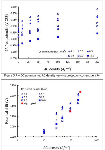
3.1 AC EFFECT ON PROTECTION POTENTIAL 61
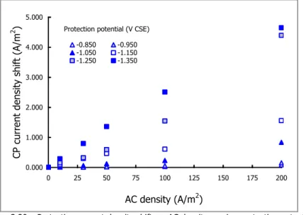
3.2 AC EFFECT ON PROTECTION CURRENT 67
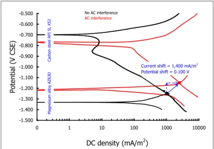
3.3 POTENTIODYNAMIC TESTS 70
3.3.1 Effect on protection potential 73
3.3.2 Effect on protection current 74
3.3.3 Galvanic anode system 76
3.4 SUMMARY 78
CHAPTER 4 – RESULTS. Part 2 – AC CORROSION MECHANISM 79
4.1 AC CORROSION RISK DIAGRAM 80
4.3 THERMODYNAMIC CONSIDERATIONS 85
4.3.1 Linear polarization resistance measurement 91
4.4 STEP 1: THE FILM BREAKDOWN MECHANISM 93
4.4.1 AC effect on passive condition 98
4.4.1.1 AC effect on critical chlorides threshold 98
4.4.1.2 AC effect on anodic and cathodic polarization curves 101
4.4.2 Alternating breakdown voltage measurement 107
4.4.2.1 Tests on stainless steels 109
4.4.2.2 Tests on carbon steel in CP condition 112
4.4.3 Some considerations 114
4.5 STEP 2: HIGH pH CORROSION 116
4.5.1 pH measurement in cathodic protection condition 117
4.5.2 AC effect on high-pH corrosion 120
4.5.2.1 Chemical corrosion 121
4.6 SUMMARY 123
CHAPTER 5 – RESULTS. Part 3 – AC CORROSION PROPAGATION 125
5.1 AC CORROSION MORPHOLOGY 125
5.2 CORROSION PENETRATION DEPTH 128
5.2.1 Extreme value statistics: theoretical background 132
5.2.2 Gumbel statistics for estimating AC corrosion penetration depth 134
5.3 NUMBER AND SIZE OF CORROSION ATTACKS 137
5.4 AC EFFECT ON MAGNESIUM ANODE CONSUMPTION 139
5.4.1 Anodic consumption: AC effect on CP current density 141
5.4.2 Anodic consumption: AC effect on anodic efficiency 142
5.5 SUMMARY 143
CONCLUSIONS 145
A AC EFFECT ON PROTECTION POTENTIAL AND PROTECTION CURRENT DENSITY 145
B AC CORROSION MECHANISM OF CARBON STEEL IN CP CONDITION 145
B.1 Step 1. The film breakdown mechanism 146
B.2 Step 2. High-pH corrosion 146
C AC CORROSION PROPAGATION 147
FUTURE WORKS 149
A LABORATORY TESTS 149
A.1 Characterization of the passive film formed on steel in CP condition 150
A.2 Film breakdown electric field measurement 150
A.3 High-pH corrosion mechanism 150
B FIELD TESTS 150
Preface
Buried pipelines used to transport hydrocarbons and dangerous fluids are provided with corrosion prevention systems, consisting of an insulating coating and a cathodic protection (CP) system. CP reduces (or halts) corrosion rate so that corrosion damage cannot occur during the designed lifetime of the structure. The presence of stray currents interference (DC or AC) may cause serious corrosion damages on a metallic structure, even under CP condition. While for DC interference there is large agreement on protection criteria for corrosion mitigation and international standards are available, AC induced corrosion represents a controversial subject and several aspects should be clarified.
AC interference can occur when a buried metallic pipe runs parallel to an interference source, as high-voltage transmission lines (HVTL) and AC traction systems, typically fed by a high voltage line at 50 or 16.7 Hz frequency. AC interference can take place by a conduction or induction mechanism and cause corrosion of the pipeline corresponding to coating defects, due to high local AC densities. Uncertainties still exist on CP criteria in the presence of AC interference and on the mechanism by which AC causes corrosion of carbon steel in CP condition.
This work is part of a two-phases project started in 2002 in the research group PoliLaPP (“Laboratorio di Corrosione dei Materiali Pietro Pedeferri”) of Dipartimento di Chimica, Materiali e Ingegneria Chimica “Giulio Natta” of Politecnico di Milano. The research project deals primarily with the study of the effects of AC interference on steel in free corrosion and CP condition.
The first phase of the experimental research was initially granted by MIUR (Italian Ministry of School, University and Research); then, from June 2006, research activities were sponsored by Italian companies. During this phase, the influence of the simultaneous presence of AC and DC on steel corrosion in different environments was studied by means of a proper electrical circuit designed in order to measure and to apply separately the DC and AC signal. The effects of AC interference on kinetics parameters (anodic and cathodic polarization curves) and on corrosion rate were widely investigated in various environments (e.g. soil-simulating solution, artificial sea water) for different metals (as carbon steel, galvanized steel, zinc and copper) varying interference conditions. Experimental tests showed that AC has a strong influence on corrosion kinetics (anodic and cathodic overpotentials) and on corrosion and equilibrium potential. A general decrease of both anodic and cathodic overpotentials and an increase of exchange current density were observed.
As regards AC corrosion of steel in CP condition, laboratory tests were carried out varying protection and interference conditions, in order to determine AC corrosion critical parameters and to assess CP criteria in the presence of AC interference. Actually, the research group is cooperating in the European Technical Committee CEN/TC 219 "Cathodic protection" in order to draw up a revised form of the Technical Specification (CEN/TS) on the evaluation of AC corrosion likelihood of cathodically protected buried pipelines, especially regarding protection criteria assessment, the identification of AC corrosion main influencing parameters and the monitoring of protection conditions.
This work is part of the second phase of the project (currently ongoing) which aims to propose a corrosion mechanism of cathodically protected carbon steel in the presence of AC interference, also on the basis of the experimental results obtained during the first phase of the research.
Different AC corrosion mechanisms of carbon steel in free corrosion as well as in CP condition have been proposed, although no one is able to fully explain the phenomenon. This doctoral thesis discusses a proposal of AC corrosion mechanism of carbon steel in CP condition. The hypothesized model represents an absolute novelty in the AC corrosion mechanism description. Electrochemical tests were carried out on carbon steel in simulated soil condition varying protection and interference conditions. Moreover, the effect of AC on protection potential and protection current and AC corrosion propagation were investigated.
This work refers to three years Ph.D. activities. Experimental tests were carried out in the laboratories of the research group PoliLaPP of Politecnico di Milano and, during an internship period of four months, in collaboration with the AC corrosion group of the Metallurgical and Materials Engineering Department of Colorado School of Mines (Golden, CO, USA).
The first part of the thesis (Chapter 1) provides a state of the art on AC corrosion characteristics and a wide description of the corrosion mechanisms proposed in literature for carbon steel in free corrosion as well as in CP condition. Chapter 2 reports a description of the experimental test conditions.
In the last part of the thesis, results are discussed as follows:
- Chapter 3 deals with the study of the effect of AC interference on protection potential and protection current density;
- Chapter 4 provides the description of the proposed AC corrosion mechanism;
- Chapter 5 discusses AC corrosion propagation on cathodically protected carbon steel and describes AC corrosion morphology. AC effect on magnesium anodic consumption is also discussed.
Chapter 1
AC corrosion
State of the Art
Corrosion by alternating current (AC) of pipelines in cathodic protection (CP) condition is not well understood, despite discussion about it dates back to the late 19th century. Nowadays,
there is agreement that at commercial AC frequencies (50 or 60 Hz) corrosion is possible, even on pipelines in CP condition and that AC corrosion is less than that caused by the equivalent direct current (DC). In the past 30 years, AC corrosion has become recognized as a threat to the integrity of underground structures, especially buried pipelines which share the way with high-tension electrical lines. The late „wake-up‟ of the industry is due to factors as the following [1]: (1) the growing number of high-voltage transmission lines, (2) more
applications using high-voltage power lines, as the high-speed railway in Europe, (3) the use of high-quality coatings that allows to increase the insulation conditions of the metal but results in high AC densities at the coating faults along the pipeline, and (4) poor or no awareness and knowledge of the phenomenon by pipeline operators. For these reasons, some aspects of AC corrosion are still under study.
Before discussing AC corrosion characteristics, a background of CP principles is presented. This overview is not exhaustive but recalls the main concepts about CP that could be helpful to understand the following discussion.
1.1 CATHODIC PROTECTION BACKGROUND [2]
CP is an electrochemical method of corrosion prevention and protection which can be applied to metals exposed to conductive environments. As shown in Figure 1.1, this technique is based on the circulation of a DC between an electrode (anode) placed in the environment and the metallic structure (cathode). The cathodic current lowers the potential of the metal and reduces (or halts) its corrosion rate.
The circulating current is obtained either by galvanic anodes(also called sacrificial anodes) or by an impressed current system. In the first case, CP is achieved through the galvanic coupling with a less noble metal (Figure 1.1a). Aluminium and zinc are used for steel protection in sea water while magnesium is employed in soil and fresh water; pure iron is usually used for stainless steel and copper alloys protection. The impressed current system makes use of a DC feeder (Figure 1.1b), with the positive pole connected to the anode, generally an insoluble metal (for example graphite, activated titanium) and the negative pole connected to the structure. CP is commonly applied to structures exposed to natural environments by means of both systems. Galvanic anodes are typically used in high conductivity environments (as sea water) and when a low current is required even in environments with low conductivity, as soil and concrete. Impressed current systems are adopted in high resistivity environments, typically soil and concrete, and are preferred when extended structures must be protected, due to the higher flexibility in the current supply.
1.1.1 The equilibrium potential
A metal (M) in an electrolyte is in equilibrium with its ions in accordance with the reaction: (Eq. 1.1) MMz ze
The equilibrium potential (Eeq) is given by Nernst‟s equation:
(Eq. 1.2) M M 0 eq a a Log K E E z
where E0 is the metal standard potential, Kis a constant, aMz+ is the metallic ions activity and
aM is the metal activity in the electrolyte. The reaction in Eq. 1.1 proceeds towards the right
(anodic process) depending on the metal‟s potential (E)compared to Eeq:
- if E > Eeq, the metal dissolves (anodic behavior);
- if E < Eeq, the metallic ions deposit (cathodic behavior).
Potential moves from equilibrium when a current is exchanged between the metal and the electrolyte (electrons must be taken from or supplied to the metal). The relationship between potential (E) and current density (i) is described by the Butler-Volmer equation:
(Eq. 1.3)
0 eq E Eeq RT zF exp E E RT zF 1 exp i iwhere i0 is the exchange current density, T is the absolute temperature, z is the number of
electrons involved in the reaction, F is the Faraday constant (96,500 C/mol), R is the universal gas constant (8.314 J/molK) and is the so-called charge transfer coefficient. The difference (E - Eeq) is usually defined as the driving voltage and measures the metal‟s tendency to
oxidize: a metal can corrode only if its potential is higher than the equilibrium potential. This may happen when a cathodic process has an equilibrium potential more noble than the metal equilibrium potential or by means of an external current source that takes electrons from the metal: this is the case of stray currents interference.
Generally, a corrosion reaction is the result of two semi-reactions: the oxidation reaction (anodic process) that releases electrons and the reduction reaction (cathodic process) that consumes electrons. For carbon steel, corrosion semi-reactions are:
(Eq. 1.5a) 2H 2e H2 cathodic process in acid environment (Eq. 1.5b) O H O2e 2OH
2
2 cathodic process in neutral or alkaline environment The number of electrons consumed (cathodic current, Ic) and produced (anodic current, Ia) is
necessarily the same (Ic = Ia) and equal to the corrosion current (Icorr). The potential of the
metal in free corrosion condition (Ecorr) is obtained by plotting anodic and cathodic curves
(Evans‟ diagram) and is given by their intersection point.
1.1.2 The protection potential
CP effectiveness depends on two distinct effects of the potential lowering: a thermodynamic effect which reduces (or brings to zero) the corrosion driving voltage, and a kinetic effect that depends on the increase of reaction resistances.
If the metal potential is below the equilibrium potential (E < Eeq), the anodic process cannot
take place and, if metallic ions are present, they are reduced to metal. This condition is called
thermodynamic immunity, i.e. the driving voltage is zero or negative. When potential lowering is not sufficient to set to zero the driving voltage (i.e., Ecorr > E > Eeq), quasi-immunity
condition is established and the potential is brought to values close enough to the equilibrium potential to make corrosion rate negligible or acceptable. Carbon steel structures in soil with potentials below -0.850 V CSE1 (or -0.950 V CSE in the presence of sulphate reducing
bacteria) operate in protection condition [2, 3]. As mentioned before, the potential lowering can
increase the anodic resistance for active-passive metals, as in the case of stainless steels in pitting corrosion condition (protection by passivity).
1.1.3 The protection current density
In order to apply CP, an adequate current must be supply to the structure. This current is determined by the so-called protection current density (iCP), which depends on cathodic
processes that take place on the metal surface. With reference to Figure 1.2, if Ie is the
current supplied to the structure by an anode, all electrons provided by the external current and by the anodic process (Ia), are consumed by the cathodic process (Ic). Accordingly, the
potential of the metal is brought to the value that verifies the following equilibrium (Kirchhoff‟s law):
(Eq. 1.6) Ie Ic Ia
The external current (Ie), which sets to zero the anodic process (Ia = 0), is called protection
current. Cathodic processes are typically oxygen reduction and hydrogen evolution, depending on the environment and on corrosion potential (Ecorr). For carbon steel in the
presence of oxygen (Figure 1.2a), the cathodic current is fixed to a limiting value determined by the amount of oxygen that reaches steel surface through diffusion process. This current (referred to a unit area) is called oxygen limiting diffusion current density (iL) and depends on
oxygen content, local turbulence, temperature and on the presence of scaling. Protection current density in soil varies from about 1 mA/m2 in clayey soils, where oxygen is almost
absent, to 150 mA/m2 in sandy soils which are well aerated [2]. When potential is lower than
hydrogen equilibrium potential, hydrogen evolution adds to oxygen reduction and the cathodic current density increases by decreasing potential.
a) b)
Figure 1.2 – CP electrochemical conditions for: a) an active material and b) a passive material [2]
1.1.4 Coating and scaling
In the presence of an insulating coating, the protection current becomes a small percentage of that required by a bare structure, since only uncoated areas as pores, defects and faults of the coating must be protected. Accordingly, the protection current density (iCP) of a coated
structure is proportional to the fraction of uncoated surface, through the relationship: (Eq. 1.7) iCP iB
1
where iB is protection current density of the bare metal structure and is coating efficiency,
defined as the unitary fraction of covered area. Coating efficiency changes with time: for a buried pipeline, it may change from 99.99% at installation to 90% after 10-20 years.
In sea water, the cathodic current causes the growth of a mix of calcium carbonate and magnesium hydroxide scale, commonly known as calcareous deposit which is particularly beneficial because reduces the protection current by acting as a barrier that limits oxygen diffusion and maintains alkalinity at the metal surface.
The protective behavior of deposits depends on sea water composition, current density and mechanical action (abrasion and vibration) that determine thickness, porosity and adherence of the scale. Once protection is interrupted, the calcareous deposit starts to dissolve.
1.1.5 Cathodic protection monitoring
CP criteria are generally based on the value of the structure-to-electrolyte potential. Potential measurement is therefore necessary in order to assess CP effectiveness [4].
The potential of a buried structure should be measured using a reference electrode placed in the immediate vicinity of the bare metal of the structure (e.g. corresponding to a coating defect) and a high impedance voltmeter whose positive pole is connected to the structure and its negative one to the reference electrode.
Since in most cases it‟s not possible to place the reference electrode so close to the structure (location 1 in Figure 1.3), the potential is measured by a reference electrode positioned far from the structure (location 2 in Figure 1.3). Nevertheless, in the presence of currents in the soil the potential measured at location 2 differs from the potential measured at location 1. The difference between the two potential measurements is equal to the algebraic sum of the ohmic voltage drops (IR drops) in the soil between the two positions (1 and 2).
Figure 1.3 – Potential measurement and its meaning [4] Generally, the measured potential (E) is the sum of three contributions [2]:
(Eq. 1.8) EEeqIR
where Eeq is equilibrium potential with respect the reference electrode used, is the
overpotential contribution with respect to the equilibrium potential and IR is the ohmic drop in the electrolyte, that depends on the reference electrode and metal distance, environment resistivity and the circulating current (second Ohm‟s law). The sum (Eeq + ) is called true
potential, also indicated as IR-free potential.
In the presence of protection currents in the soil, the potential measured at location 2 is generally more negative than the potential measured at location 1 due to the IR drop contribution. In the presence of DC stray currents, the potential measured at location 2 may be either more negative or more positive than the potential at location 1, according to the sense of currents.
The ohmic contribution (IR in Eq. 1.8) contaminates the potential measurement. It decreases when the reference electrode is placed close to the pipeline and, therefore, the simplest technique to minimize IR drop consists in placing the reference electrode as close as possible to the structure. Of the three parameters determining ohmic drop (resistivity, current and distance), resistivity plays the most important role. Potential is more negative than the true potential when stray current is cathodic and more positive when stray current is anodic; as a result, cathodic or anodic interference may indicate overprotection or severe corrosion, respectively. For a correct potential measurement, ohmic drop must be evaluated or eliminated by means of suitable techniques [2, 4] available but not discussed in this work.
1.2 ELECTRIC INTERFERENCE
Corrosion due to DC or AC interference could cause severe damage on buried structures, even in CP condition. As a general definition, interference is any alteration of the electric field caused by a foreign structure. If the foreign body is a conductor, the current is intercepted; if it is an insulator, the current is withdrawn. In both cases, there is a redistribution of current and potential lines within the electrolyte.
1.2.1 Stationary and non-stationary interference
Interference can be stationary or non-stationary [2]. Stationary interference occurs when the
structure is immersed in a stationary electric field generated, for instance, by a CP system, and the effect is great if the structure is close to the groundbed. Figure 1.4 reports two general cases of DC stationary interference. In the first case (Figure 1.4a), the interfered pipeline crosses the protected one. The zone close to the groundbed tends to gather current from the soil, which is released at the crossing point causing corrosion. In the second case (Figure 1.4b), the two pipelines are parallel and the current is released more extensively, typically in zones in contact with low resistivity soil. In both cases, if the interfered structure is provided with an integral coating, interference cannot take place, but when the coating has faults, corrosion could be very severe since current concentrates in them.
Non-stationary interference takes place when the electric field is variable, as in the typical case of stray currents dispersed by traction systems, illustrated in Figure 1.5 in the case of a DC traction system. Interference takes place only during the transit of the train in the anodic zone corresponding to the substation and, in spite of the limited duration, the effects may be severe due to the high circulating current.
Electric interference could be due to DC or AC stray currents. While for DC interference corrosion there is large agreement on protection criteria for corrosion mitigation and international standards are available for several years [5-7], AC induced corrosion represents a
controversial subject and many aspects need to be clarified, especially with respect to the mechanism by which AC causes corrosion of carbon steel in CP condition. An extensive discussion about the criteria of DC interference acceptance and corrosion prevention is provided in [2] and is not reported here.
Figure 1.4a – Stationary interference between two crossing pipelines [2]
Figure 1.5 – Non-stationary interference by a DC traction system [2]
1.3 AC INTERFERENCE
Generally, electric interference requires the existence of a source of disturbance, a coupling mechanism and a receptor. In the case of AC interference, the source of disturbance is the power line, the receptor is the metallic structure (as a pipeline) and the coupling between the power line and the pipeline occurs by a capacitive, resistive or an inductive mechanism [1, 2].
Typically, AC interference sources are high-voltage overhead or underground power lines and AC traction systems (usually fed by a parallel high voltage line at 50 Hz or 16.7 Hz). AC interfering sources are described in further details in Paragraph 1.3.1. The increased number of AC corrosion-related failures is associated to the parallelism between buried pipelines and AC high voltage transmission lines which use the same right of way. The severity of interference is directly related to the pipeline‟s electrically continuous length that runs parallel to the source and to its external insulation from ground.
1.3.1 AC interference sources
The main AC interference sources are high-voltage transmission lines (HVTL) and AC traction systems.
1.3.1.1 High-voltage transmission lines
HVTL are used to transmit electric power over relatively long distances, usually from a central station to substations. They are also used for electric power transmission from one central station to another for load sharing. HVTL are made of high voltage (between 138 and 765 kV) overhead or underground conducting lines of either copper or aluminium. A transmission line can refer either to a single cable carrying electricity over a transmission system, or to the physical path that distributes electricity from producer to consumer. However, a distribution line is normally considered as a line that carries less than 69 kV and is used to distribute power from HVTL to end-use customers. Transmission lines, when interconnected each other, become the high voltage transmission network. The electric power distribution circuit is usually represented as two wires that bring electricity to users. In AC circuits, the two wires take turns with the frequency of the applied AC voltage.
Transmission lines mostly use a three-phase AC system, although single phase AC is sometimes used in railway electrification systems. High-voltage DC line is used only for very long distances (typically greater than 400 miles, or 600 km), for submarine power cables (typically longer than 30 miles, or 50 km) or to connect two non-synchronized AC networks. Electrical power is transmitted at high voltages to reduce energy lost in long distance transmission, through overhead power lines (Figure 1.6). High-voltage overhead conductors are not covered by insulator.
Figure 1.6 – Example of HVTL Figure 1.7 – Italian high-speed railway [8] The conductor material is usually an aluminum alloy, reinforced with steel strands. Copper is sometimes used for overhead transmission but aluminum is lower in weight and cost. Voltages of 66 kV and 33 kV are usually considered subtransmission voltages but are occasionally used on long lines with light loads. Voltages less than 33 kV are usually used for distribution. Voltages above 230 kV are considered extra high voltage and require different design compared to equipment used at lower voltages to maintain safety requirement. Transmission substations decrease the voltage of incoming electricity by means of voltage transformers, allowing the connection of HVTL and the lower voltage distribution network. Finally, at the point of use, the energy is transformed to low voltage (varying by country and customer requirements).
1.3.1.2 AC high-speed railway lines
There is a wide variety of electric traction systems around the world, which have been built according to the type of railway, its location and the available technology at the time of installation. Electric railway network can use either alternating or direct current. AC systems always use overhead wires; DC systems can use either an overhead wire or a third rail. The contact between the traction system and the power supply is guaranteed by a pantograph; the return circuit to the electric substation is given by the rails, connected to the substation. AC power transmission system along the line is used mainly for long distance; DC, on the other hand, is the preferred option for shorter lines, urban systems and tramways. It is easier to increase AC voltage than DC voltage, so it is easier to supply more power with an AC power system. The 25 kV AC railway electrification system is commonly used in railways worldwide, especially on high-speed lines. The choice of 25 kV is related to the efficiency of power transmission as a function of voltage and cost. A 25 kV AC system uses only one phase of the normal three-phases power supply. Electric power from a generating station is transmitted by overhead high voltage lines to substations, where a transformer lowers the voltage to 25 kV which has become an international standard.
The Italian high-speed railway (Rete Alta Velocità - Alta Capacità (AV/AC), RFI – Rete Ferroviaria Italiana, Gruppo Ferrovie dello Stato Italiane Spa [8], Figure 1.7) uses in non-urban
sections a single-phase 25 kV AC electrification system at 50 Hz frequency. This system is innovative compared to 3 kV DC system used in the railway network and is the most used in Europe for high-speed/high-capacity lines. The power system is connected directly to the national grid at 380 kV and adopts the ring system that provides both efficacy and safety. In this system, power substations are connected each other with the first and the last substation connected to two central national grids at 380 kV by means of transformers that reduce the voltage to 150 or 132 kV (depending on the Italian geographic area). Electrical substations reduce AC voltage by means of transformers with the primary at 150 or 132 kV and the
secondary connected to two terminals at +25 kV (contact line) and -25 kV (feeder). The resulting system is the so-called 2x25 kV–50 Hz AC electrical system.
As mentioned before, in the case of AC interference, the coupling between the power line and the pipeline can occur by a capacitive, resistive or an inductive mechanism [1, 2, 9-11].
1.3.2 Capacitive coupling
The capacitive coupling is due to the influence of two or more circuits upon one another, through a dielectric medium as air, by means of the electric field acting between them [9]. The
electric field associated with power conductors causes a current flow between a nearby aboveground metallic structure and earth. Since the capacitance between the pipeline and earth is negligible, the electric field normally doesn‟t induce an AC voltage on buried pipelines, even when dielectric coatings are used, but only on aboveground sections of the pipeline. The magnitude of the total stray current is a function of the size of the structure, its proximity to power conductors, the voltage of power conductors and their geometrical arrangement.
1.3.3 Resistive coupling
The resistive coupling is due to the influence of two or more circuits on one another by means of conductive paths (metallic, semi-conductive, or electrolytic) between the circuits [9]. This is
the case of grounded structures of an AC power system that share the earth with other buried structures. Coupling effects may transfer AC to a metallic buried structure in the form of alternating current or voltage.
Whenever a grounded power system has unbalanced condition, current may flow to the earth. Indeed, resistive coupling is primarily a concern during a short-circuit condition on an AC power system, for instance when a large part of the current in a power conductor flows to the earth by means of foundations and grounding system of a tower or a substation. The current flow raises the electric potential of the earth near the structure, often to thousands of Volts with respect to remote earth, and can result in a considerable AC voltage across the coating of a metallic structure, as a pipeline. This can damage the coating, or even the structure itself. The potential difference between the earth and the structure can represent an electric shock hazard. Under some circumstances, the electric potential of the structure may be raised enough to transfer hazardous voltages over considerable distances, particularly if the structure is well coated. Resistive coupling effects are strongly dependent on a large number of factors, as the total short-circuit current, the power line overhead ground wire type, the size of foundations and grounding systems of towers or substations, the electrical resistivity of the soil as a function of depth and the distance between the power system and the affected metallic structure.
Lightning strikes to the power system can also initiate fault current conditions [9]. Lightning
strikes to a structure or to earth in the vicinity of a structure can produce electrical effects similar to those caused by AC fault currents. If a lightning strike occurs between the tower structure and an overhead cloud, the potential of the tower could be raised to an extremely high voltage, with a current flow from the tower structure to the earth. The current flows to the earth through the grounding system and spreads uniformly through the earth (assuming a homogenous soil resistivity) in all radial directions. Therefore, the ground around the pipeline will be at a relatively high potential with respect to the pipeline potential and this could result in the coating damage. Fault currents can create a hole in the coating or can enlarge it by removing the previously adherent coating due to heating effect.
1.3.4 Inductive coupling
The inductive coupling is due to the influence of two or more circuits upon one another by means of the magnetic flux that links them [9]. AC flow in a power conductor produces an
alternating magnetic field around it which induces an AC in the coated pipeline, i.e. the power line and the pipeline behave as two coils of an auto-transformer. The current flow in the conductor creates an electromagnetic field which lies at right angles to the current that produces it. The magnetic field expands away from the conductor and then collapses towards the metallic structure.
If a pipeline is close enough and parallel to the electrical transmission line, the magnetic field will cross the pipeline with the induction of an AC voltage on the pipeline (Figure 1.8). In the case of a three-phases AC system where the current magnitudes in the three phases are equal and the three overhead conductors are equally distant from the axis of the pipeline, no voltage will be induced on the pipeline. However, the more frequently configuration (in which there is no symmetry between the three-phases conductors and the pipeline) will result in a measurable induced AC voltage [11] (Figure 1.9).
In conclusion, in the case of a buried pipeline, inductive and resistive coupling must be considered.
Figure 1.8 – Inductive coupling between an AC conductor and a buried pipeline [11]
1.4 CHARACTERISTICS OF AC CORROSION
As discussed before, a buried pipeline which shares a common path with AC transmission lines may be interfered by magnetic and electric fields generated by the power system (interference source). In the presence of AC interference, corrosion of the pipeline can occur. The technical specification CEN/TS 15280:2006 [12] (currently under review) reports that
factors which mainly influence AC corrosion phenomena are: - induced alternating voltage;
- AC density on the exposed metal; - DC polarization level;
- size of coating faults; - local soil resistivity;
- local soil chemical composition.
A brief description of AC corrosion characteristics is reported below. Part of the discussion refers to the technical committee report “AC corrosion State-of-the-Art: Corrosion Rate, Mechanism, and Mitigation Requirements” [13] prepared in January 2010 by NACE
International Task Group 327. NACE International (NACE, National Association of Corrosion Engineers) is the leader in the corrosion engineering and is recognized around the world as the premier authority for corrosion control solutions.
As mentioned in the preface, this work is part of a research project carried out by the group PoliLaPP (“Laboratorio di Corrosione dei Materiali Pietro Pedeferri”) of Politecnico di Milano on the study of AC effects on metals corrosion, even in CP condition. The research group has participated to the preparation of the aforementioned report published by NACE International.
1.4.1 Alternating voltage (AV)
The technical specification CEN/TS 15280:2006 [12] reports alternating voltage (AV) of an
interfered structure as the most important parameter to take into account in order to evaluate AC corrosion likelihood. AV can either be calculated or directly measured on the structure itself. AV measurement should be performed on pipelines or sections of them where unacceptable AC interference is suspected (or may be expected) based on map observation, calculation, or routine measurements.
AV measurement should be performed in a first instance on all test points, CP control stations, insulating joints, wherever an accessible measuring cable is connected to the pipeline. At a later stage, these measurements may be restricted to a few particular positions, chosen along the most influenced areas. For routine measurements, short duration AV measurements are sufficient and are carried out by means of a high impedance AC voltmeter between the metal structure and the reference electrode placed over the pipe; for a more correct measurement, the electrode should be located at the remote earth. For long-term evaluation, a data recorder instead of a voltmeter should be used.
The technical specification CEN/TS 15280:2006 [12] reports that, in order to reduce AC
corrosion likelihood, the pipeline AV should not exceed at any time: - 10 V where the local soil resistivity is greater than 25 Ωm; - 4 V where the local soil resistivity is lower than 25 Ωm.
These values should be considered as threshold limits which significantly reduce AC corrosion likelihood. It should be pointed out that these values are based on long term practical experience of European operators and not on a scientific approach.
At present in the U.S., AV threshold is mostly driven by safety considerations. The standard NACE SP0177-2007 [9] reports that AV on structures must be reduced and maintained at safe
levels to prevent shock hazards to personnel. The shock hazard degree depends on several factors, as the voltage level and duration of human exposure, human body and skin conditions, and the path and magnitude of any current conducted by human body. The U.S.
standard [9] reports that a steady-state touch AV of 15 V or more with respect to local earth
constitutes a shock hazard. AV measurements should be compared with the threshold limits specified above. These AV limits are sometimes considered too restrictive for pipelines parallel to 50 or 60 Hz overhead HVTL without a corrosion failures history. Furthermore, the assessment of AC corrosion threat only on the basis of AV may be misleading and different factors, as AC density, the ratio between AC and DC densities, metal IR-free potential should take into account to define corrosion likelihood.
1.4.2 AC density
AC corrosion of steel is lower than DC corrosion, being in the range between 0.1 and 5% with respect to corrosion caused by the same amount of DC, as reported for instance by Pookote and Chin as from 1978 [14]. By laboratory test results on carbon steel in soil-simulating
solution, Goidanich et al. [15] reported that AC corrosion is lower than 4% with respect to DC
corrosion and decreases by increasing AC density.
Although several authors report the existence of a critical AC density threshold below which AC corrosion doesn‟t occur, the magnitude of this critical value is debated and large data variability can be found depending on interference condition and environment. In 1986, a corrosion failure on a high-pressure gas pipeline in Germany was attributed to AC corrosion. Field and laboratory investigations indicated that AC corrosion can occur on coated steel pipelines even if protection criteria are met. The main conclusions of German investigators can be summarized as follows [16]:
- AC corrosion doesn‟t occur if AC density is lower than 20 A/m2;
- AC corrosion is unpredictable if AC density is between 20 and 100 A/m2; - AC corrosion occurs if AC density is greater than 100 A/m2;
- the highest corrosion rates occur corresponding to coating holidays with a surface area between 100 and 300 mm2.
Chin and Fu [17] reported that at 2,000 A/m2 AC density the passive layer formed on mild steel
in passivating sodium sulphate solution appears completely destroyed. On the basis of laboratory tests, Carpentiers and Pourbaix [18] concluded that AC corrosion is not related to
any particular critical AC density value. Jones [19] observed that corrosion rate of carbon steel
specimens in de-aerated sodium chloride solution exposed to 300 A/m2 AC density increases
of four to six times. Yunovich and Thompson [20] state that AC density in the order of 20 A/m2
can significantly increase steel corrosion, with high penetration corrosion rate and general attack. Further, the authors stated that probably a theoretical „safe‟ AC density (a threshold below which corrosion doesn‟t occur) doesn‟t exist. However, a practical AC density below which the corrosion rate increase is not considerable may exist.
The technical specification CEN/TS 15280:2006 [12] reports that a pipeline is considered
protected by AC corrosion if the root mean square AC density is lower than 30 A/m2. In
practice, the evaluation of AC corrosion likelihood on the basis of AC density is: - AC density lower than 30 A/m2: no or low corrosion likelihood;
- AC density between 30 and 100 A/m2: medium corrosion likelihood; - AC density higher than 100 A/m2: very high corrosion likelihood.
1.4.3 AC density/DC density ratio (iAC/iDC)
The technical specification CEN/TS 15280:2006 [12] discusses AC corrosion likelihood also in
terms of the ratio between AC and DC densities, providing the following supplementary indications:
- iAC/iDC lower than 5: low corrosion likelihood;
- iAC/iDC between 5 and 10: corrosion likelihood can exist and further investigation is
- iAC/iDC greater than 10: high corrosion likelihood and mitigation measures are normally
taken.
The iAC/iDC ratio doesn‟t depend on the area of the metal exposed to the electrolyte.
Nevertheless, it should be pointed out that the only use of iAC/iDC ratio is not recommended to
assess AC corrosion risk, because of the misleading meaning that could be associated to it. For instance, a iAC/iDC ratio of 10 can represent different interference conditions, e.g. 30 A/m2
AC density in the presence of 3 A/m2 DC density or 3 A/m2 AC density in the presence of 0.3
A/m2 DC density. Even if the i
AC/iDC ratio is the same, the interference condition (and the
related corrosion risk) is different, i.e. 3 A/m2 AC density is not recognized as a critical value,
differently from 30 A/m2 (Paragraph 1.4.2).
1.4.4 Soil characteristics
AC density (iAC) at a coating defect depends on induced AV on the pipeline and on soil
resistivity by the following equation: (Eq. 1.9) d AV 8 iAC
where is soil resistivity and d the diameter of a circular holiday having a surface area equal to that of the real holiday. AC density varies linearly with AV and depends on soil characteristics by its resistivity, i.e. AC density is greater in soil with low electrical resistivity. Moreover, AC density increases by decreasing the dimension of the coating defect (for a fixed AV value). The local soil resistivity is controlled by the amount of soluble salts and by water content and is strongly influenced by the electrochemical processes occurring on the metal surface in CP condition. Indeed, the presence of a cathodic current results in the migration of cations towards the cathodically protected metal and in the pH increase of the electrolyte close to the metal, due to the cathodic reactions that occur on the metal surface (Eq. 1.5). Depending on soil composition, the electrical resistance of the soil near the coating defect can either increase or decrease with time due to chemical modifications according to the pH increase. In particular, earth-alkaline ions (as Ca2+ and Mg2+) form hydroxides with relatively
low solubility. The pH increase shifts the carbonate-bicarbonate equilibrium towards the precipitation of carbonates, with the formation of a calcareous deposit [2]. If a compact
deposit is formed on the metal surface, the coating defect resistance can significantly increase up to a factor of 100. Otherwise, alkaline cations (as Na+, K+ or Li+) form highly soluble
hygroscopic hydroxides. As a consequence, a low electrical resistance due to the high ions concentration is observed. This process can decrease the electric resistance at the coating defect up to a factor of 60. According to this description, AC density on a coating defect is therefore dependant on [12]:
- the size of the holiday; - the specific soil resistivity;
- the ratio of alkali and earth-alkali ions;
- the amount of hydroxyl ions produced, due to the cathodic current.
Furthermore, the presence of earth-alkaline ions (such as Ca2+ and Mg2+) extends the
passivity region expected from Pourbaix diagram of iron [21].
1.4.5 Corrosion rate
Large corrosion rate data variability can be found in literature, due to the presence of several factors that contribute to AC corrosion. Moreover, there is scarcity of data about the time-dependence of AC corrosion of carbon steel in CP condition. Some AC corrosion rate data referred to cathodically protected steel structures as well as to structures in free corrosion
condition are reported in this section. Ragault [22] carried out on-site experiments on a
polyethylene coated steel gas transmission buried pipeline cathodically protected and parallel for 3 km with a 400 kV HVTL. The pipeline showed corrosion with corrosion depths equal to 0.1 up to 0.8 mm after one year of installation. On-site experiments were carried out as close as possible to field conditions. 12 coupons were installed for 18 months close to the test posts where the worst cases of corrosion were found. Results showed that corrosion depth was comprised between 0.3 and 0.5 mm with AC density from 30 and 4000 A/m2 and on-potential
between -2.0 and -2.5 V CSE. The author states that there is no clear relation between AC density level and corrosion penetration depth, but high level of AC density may be an indication of high AC corrosion risk. Wakelin et al. [23] discussed some cases of cathodically
protected steel pipeline failures in Ontario (Canada), where AC corrosion was suspected. Authors report that an AC density of approximately 100 A/m2 or more provokes corrosion,
even if the DC potential indicated that corrosion should not occur. Maximum corrosion rates calculated were found to increase with AC density. The authors report also that, with the exception of AC density, there were no other common denominators which linked all of the case histories together, even though there were a number of factors which may be important indicators of AC corrosion activity. Authors compare their results with some previous corrosion rate data taken from literature of cathodically protected steel in the presence of AC interference (Figure 1.10).
Song et al. [24] studied AC corrosion of cathodically protected buried pipeline by means
corrosion coupons and ER (electrical resistivity) probes. Corrosion coupons simulate a coating defect and are usually made of a steel plate having a known bare surface area. In ER probes, corrosion rate is obtained by measuring the electric resistance change of a steel plate integrated in a coupon, due to the metal loss caused by corrosion. Details about this monitoring technique will be given in Paragraph 1.8.2.
Where pipeline was cathodically protected below –1.0 V CSE (on-potential, including IR drop contribution), AC corrosion rate was affected not by AV but by both frequency and AC density. Authors obtained an experimental relation between corrosion rate and AC density: corrosion rate increases linearly with AC density with slope of 0.619 if measured by corrosion coupon (Figure 1.11a) and 0.885 if measured with ER probes (Figure 1.11b).
Nielsen and Galsgaard [25] reported field test corrosion rates measured by means of corrosion
ER coupons connected to a buried pipeline in CP condition. Two periods with different DC on-potential (including IR drop contribution) were established. In the first period, on-on-potential was kept quite negative to give excessive CP (-1.5 V CSE). In the second period, on-potential was -1.25 V CSE. The first condition produced the highest corrosion rates: authors recorded corrosion rate peaks as high as 10 mm/y during a period of two weeks (Figure 1.12).
A laboratory study of Yunovich and Thompson [20] reports corrosion rates of carbon steel
specimens cathodically protected in the presence of 20 A/m2 (low) and 500 A/m2 (high) AC
densities. Applied cathodic potential shifts were 0 mV (no CP), 100 mV (low) and 300 mV (high). The highest corrosion rates were measured in the presence of high CP and high AC densities (Figure 1.13). Goidanich et al. [15] reported results of weight loss tests on carbon
steel specimens in aerated and de-aerated soil-simulating solution in the absence of CP. In the presence of 10 A/m2 AC density, corrosion rate is nearly twice with respect to that
measured for specimens in free corrosion condition. In the presence of AC densities higher than 30 A/m2, corrosion rate increase can be considered unacceptable. The discussed
literature data show that there is controversy about AC corrosion rate; furthermore, the relation between corrosion rate and AC parameters (as AC density) is not well understood.
Figure 1.10 – Corrosion rate vs. AC density [23]
a) b)
Figure 1.11 – Corrosion rate vs. AC density measured by: a) corrosion coupons and b) ER probes [24]
Figure 1.13 – Relative corrosion rate varying test conditions [20]
1.4.6 Frequency effect
There is agreement about the effect of the frequency of the signal on AC corrosion: corrosion rate decreases by increasing frequency [14, 17, 26-32]. Nevertheless, AC at power frequencies of
50 or 60 Hz can cause corrosion.
Fernandes [26] discussed a kinetic effect of frequency on corrosion: with the increase of
frequency, the interval between successive anodic and cathodic half-cycles becomes shorter and the metallic ions formed in the anodic cycle would be available for the immediate redeposition in the cathodic cycle. In addition, the author states that at high frequencies hydrogen atoms formed during the cathodic cycle haven‟t enough time to coalesce and form hydrogen gas molecules. In this way, in the next anodic half-cycle, a layer of hydrogen atoms covers the metal surface and prevents the metal dissolution reaction.
The example reported below is taken from a Yunovich and Thompson study [32]. Authors
calculated the current flow (corrosion current) through a steel specimen exposed to soil using an equivalent analog circuit (Randle‟s model, Figure 1.14). The circuit consists of a double layer capacitance (C1), the solution resistance (Rs) and the “effective resistance” (Reff) that
represents the combination of the charge-transfer and Warburg (diffusion-related) impedances. The circuit also includes an AC power source (HVTL). The analysis allows to simulate the electric behavior of the metal and to calculate the current passing through each component of an electric circuit varying the imposed AC frequency. AV is 24 V and AC density on the specimen is approximately 400 A/m2.
Figure 1.15 shows the current passing through Reff (related to corrosion process) and the
current passing through Rs (the total current in the circuit) varying the frequency of the AV
applied by the AC source. The impedance of the capacitor (C1) and the current through Reff
decreases with increasing frequency (and become zero if the frequency is infinite). Nevertheless, although most of the current at 60 Hz passes through the capacitor (C1) and thus does not affect corrosion reactions, there is an amount of AC (approximately 0.3% of the total current) that flows through Reff at 60 Hz frequency [32].
Figure 1.14 – Electric equivalent circuit [32]
Figure 1.15 – Electrical response of the circuit in Figure 1.14: the red line is the total AC, the green line is the AC
passing through Reff[32]
1.5 MORPHOLOGICAL CHARACTERISTICS
AC corrosion is localized. Camitz et al. [33] studied AC corrosion in field on steel test coupons
in CP condition and exposed to different AC densities. Two series of tests were performed, one at 10 V AC for almost two years, and another one at 30 V AC for 1.5 years. Authors recorded the IR-free potential (off-potential) of the test coupons with an oscilloscope: the potential varied according to the AV signal and, during the positive half cycle, off-potential shifted in the anodic direction to values less negative than the limit value for CP, meaning that CP was periodically lost due to AC interference. In several cases, the potential shifted to values even less negative than free corrosion potential. The authors report that corrosion attacks could be divided into three groups:
- small point-shaped attacks evenly distributed across the surface (uneven surface); - large point-shaped attacks evenly distributed across the surface (rough surface); - few large, deep local attacks on an un-corroded surface (“pocked” surface).
Nielsen and Cohn [34] described a corrosion tubercle of “stone hard soil” comprising a mixture
of corrosion products and soil often observed to grow on the coating defect surface in the presence of AC interference.
Figure 1.16 – Schematic illustration of the tubercle of “stone hard soil” that grows at the coating defect in connection
with AC corrosion [34]
Figure 1.16 shows a schematic illustration [34]. The specific resistivity of the tubercle is
expected to be significantly lower than the specific resistivity of the surrounding soil.
In addition, the effective area of the tubercle is considerably greater than the original coating defect. Both processes tend to decrease the spreading resistance of the associated coating defect during the corrosion process, making the corrosion process autocatalytic. Ragault [22],
describing 31 AC corrosion cases on a polyethylene-coated gas transmission line, reports that corrosion products consisted mostly of magnetite mixed with soil. Williams [35] also indicates
that the main corrosion product on steel interfered by AC is magnetite. Wakelin et al. [23],
reported that the aspect of the pit site (i.e. hard hemisphere of soil surrounding the pit site, smooth round dish-shaped pits having a minimum diameter of 1 cm, hard tubercles covering the pit, etc.) could help to determine if AC corrosion is the primary cause of the failure. In order to provide supplementary information, a case study of failure analysis carried out by Linhardt and Ball [36] is reported.
1.5.1 A corrosion case study adapted from literature [36]
During a routine inspection of a natural gas transmission pipeline (pressure 25 bar, 150 mm inner diameter, 4.5 mm wall thickness, 45 years in service), a leak was identified by discoloration of plants. The area was excavated and the leaking section of the pipe (1.5 m long) was transferred to a laboratory for examination, together with samples from the surrounding soil. The leak was covered by a large cap (approximately 200 mm diameter) of hard, agglomerated soil.
The pipeline runs parallel to a railway (16.7Hz system) for approximately 10 km, and the leak occurred at the end of this section. The pipe was coated with bitumen, and CP was checked every three years by extensive measurements. The protection criterion was met at all times, and the last check did not indicate the presence of a defect. The influence of AC wasn‟t considered critical. Measurements after the failure indicated AV peaks of 20 to 30 V in the affected region. Figure 1.17 shows the hard cap of soil adhering to the pipe that covers the leak. Polyester resin was used to impregnate the surface of the cap to stabilize its structure. After that, the bituminous coating around the cap was peeled off, and the whole cap was carefully removed from the pipe (Figure 1.18). The bituminous coating was brittle. In the area surrounding the leak, the coating was rather soft and sticky, well-adherent to the steel. After cleaning, localized attacks with deep cavities in a generally passive surface were found (Figure 1.19). The cap was cut perpendicular to the pipe‟s axis, in the plane of the leak position. Figure 1.20 shows the cross section of the soil cap removed from the pipe. Above the corroded area, the original layer of the coating is no longer visible. Instead, the bitumen formed a bubble-like black structure (Material A). Regions of soil material (Material B) and a white substance (Material C) separated by thin layers of material A were found. Samples of
materials A, B, and C were characterized by wet chemical analysis and by energy dispersive X-ray analysis (EDX). Results are summarized as follows:
- Material A: the black material was based on bitumen with different amounts of iron oxide (mainly magnetite) and a sodium compound, presumably carbonate. Inorganic components were finely dispersed in the bituminous matrix;
- Material B: the grey material was based on the soil material, a silicate incorporating minor amounts of alkali (Na, K) and earth-alkali (Ca, Mg) ions. The pH of the aqueous extract of the soil (1 g/10 mL) taken far from the corrosion site was 8.2. Soluble sodium content increases by decreasing the distance from the corrosion site and was found as high as 12,500 mg/kg inside the cap;
- Material C: the white substance was identified as a mixture of NaHCO3 and Na2CO3 in a
molar ratio of 1:1, without any significant impurities. The pH of a solution of 1 g in 10 mL distilled water was 9.6.
This case of pipeline corrosion was characterized by localized attack similar to pitting. The bituminous coating was found to be deformed like a bubble and magnetite was found as the major corrosion product; however, it didn‟t form a protective layer and was dispersed in the bituminous material. The large volumes of sodium carbonate embedded in the bubble indicate a high cathodic activity in the leak area. Failure analysis indicates that corrosion may be compatible with AC corrosion. These specific features are:
- strongly localized, pitting-like attack;
- finely dispersed magnetite as the predominant corrosion product; - accumulation of large amounts of sodium carbonate;
- indications of local temperature excursions to values softening bitumen;
- mechanical forces mixing soil, bitumen, and sodium carbonate as could be achieved by slowly evolving gas bubbles.
Figure 1.17 – The soil cap that covers the leak [36] Figure 1.18 – The leak of the pipe after the removal of
the soil cap [36]
Figure 1.19 – The corroded area after cleaning. The
1.6 AC CORROSION MECHANISM
Different theories have been proposed about the mechanism by which AC produces and enhances corrosion of carbon steel (even in CP condition), although no one is able to fully explain the phenomenon. Some AC corrosion mechanisms proposed in literature are now discussed. They refer to cathodically protected structures as well as to structures in the absence of CP (free corrosion condition).
The technical specification CEN/TS 15280:2006 [12] reports a simplified description of the AC
corrosion mechanism described below. As reported by the technical specification, a corrosion reaction is associated with a current that leaves the metal surface (anodic behavior). In the presence of an AV induced on the pipeline in CP, an alternating current flows through the metal surface corresponding to the coating defects. The intensity of this current depends on the impedance of the system. During the positive half wave, the current leaves the metal surface if the AV is sufficiently large. This current causes the charge of the double layer capacitance and oxidation of the pipeline.
The technical specification reports that, since the current that leaves the metal surface is consumed by several non-corrosive processes, generally voltages between 4 V and 10 V are required to result in a significant corrosion attack of the metal. Nevertheless, as discussed before, various additional parameters influence this process, as leakage resistance of the defect, soil composition, CP level.
The electrochemical processes on the metal surface are schematically illustrated in Figure 1.21. During the positive half wave, the bare metal surface is oxidized resulting in the formation of a passive film, due to the current that leaves the metal surface. During the negative half wave (cathodic behavior), the passive film is reduced to iron hydroxide. In the following anodic cycle a new passive film grows. As a result of the further reduction of the passive film, the amount of iron hydroxide increases. Hence every AC cycle results in the oxidation of the metal. In the long term this can result in a significant metal loss.
Figure 1.21 – Scheme of the AC corrosion mechanism with CP as reported by the technical specification [12]
Nevertheless, the description of the AC corrosion mechanism reported by the technical specification is not exhaustive, particularly as it applies to CP in soils. As a result, several proposals of AC corrosion mechanism could be found in literature. Some aspects need a further investigation, as the individuation of the more influencing parameters in the AC
corrosion process, the existence of a critical value of AC density (or AV), the assessment of CP criteria in the presence of AC, the influence of AC on the electrochemical behavior of the metal (thermodynamic and kinetic effects). Some proposals of AC corrosion mechanism are discussed in further detail in the following.
1.6.1 Electrical equivalent circuit analysis
Nielsen and Cohn [34] proposed an electrical equivalent circuit analysis helpful to understand
the AC corrosion process and mechanism. An electrical equivalent diagram represents the impedances existing between pipe and remote earth and can model the AC corrosion process on the metal. Figure 1.22 shows the electrical circuit suggested by the authors [34]. AC and DC
sources impose a DC and AC voltage between the pipeline and remote earth at a specific location or coating defect. In the case of AC interference on a pipeline in CP condition, the AC source is the HVTL, whereas the DC source represents the CP system. E01 and E02 represent
the equilibrium potentials of the two reactions occurring at the metal interface (anodic and cathodic reactions). Other elements represent impedances related to the physical and chemical factors existing in the current path from remote earth to the coating defect.
Authors divided these elements in static and dynamic elements. Static elements are defined as elements which impedance is frequency-independent. Spread resistance and charge transfer resistance are examples of static elements. Conversely, dynamic elements are frequency-dependant. These include the double layer capacitance (interfacial capacitance) and diffusion elements. Each element is described below.
Soil resistance or spread resistance (RS): the current flows through the soil from remote earth to the coating defect. The ohmic drop (IR) provided by the soil is controlled by factors related to the soil solution resistance, soil porosity and geometrical factors existing at the interface between the soil and the coating defect. Concerning geometrical factors, the majority of the IR drop takes place close to the pipe-to-soil interface, at the coating defect. Indeed, the current flux lines concentrate near the defect, causing a geometrical spread effect and an associated spread resistance (Figure 1.23).
Figure 1.22 – A schematic illustration of the electrical equivalent circuit proposed by Nielsen and Cohn [34]
![Figure 1.8 – Inductive coupling between an AC conductor and a buried pipeline [11]](https://thumb-eu.123doks.com/thumbv2/123dokorg/7501206.104501/18.774.218.537.334.619/figure-inductive-coupling-ac-conductor-buried-pipeline.webp)
![Figure 1.11 – Corrosion rate vs. AC density measured by: a) corrosion coupons and b) ER probes [24]](https://thumb-eu.123doks.com/thumbv2/123dokorg/7501206.104501/23.774.80.720.319.511/figure-corrosion-rate-density-measured-corrosion-coupons-probes.webp)
![Figure 1.28 – Pourbaix diagram: the hatched area indicates the critical AC corrosion zone [39]](https://thumb-eu.123doks.com/thumbv2/123dokorg/7501206.104501/35.774.152.643.703.976/figure-pourbaix-diagram-hatched-area-indicates-critical-corrosion.webp)
![Figure 1.38 – Polarization curves of carbon steel in soil-simulating solution varying AC density [46]](https://thumb-eu.123doks.com/thumbv2/123dokorg/7501206.104501/39.774.207.591.760.999/figure-polarization-curves-carbon-simulating-solution-varying-density.webp)
![Table 1.1 – Corrosion level of the coupon related to the charge required for the passivation [12]](https://thumb-eu.123doks.com/thumbv2/123dokorg/7501206.104501/44.774.52.698.340.444/table-corrosion-level-coupon-related-charge-required-passivation.webp)