Universita della Calabria
Dipartimento di Ingegneria per l'Ambiente e il Territorio e Ingegneria
Chimica (DIATIC)
Scuola di Dottorato di Ricerca in
Scienze e Ingegneria dell’Ambiente, delle Costruzioni e dell’Energia - XXIX ciclo
CHIM/07 FONDAMENTI CHIMICI DELLE TECNOLOGIE
Development of Tailored Hydrogel Composite Membranes for
Application in Membrane Contactors
Ph.D. Candidate
Shabnam Majidi Salehi
Tutors
Prof. Efrem Curcio
Dr. Gianluca Di Profio
Dr. Enrica Fontananova
i
Abstract
This work was performed during the period from November 2013 to May 2015 in the Institute on Membrane Technology (ITM-CNR) at the University of Calabria (UNICAL), under supervision of Prof. Efrem Curcio, Dr. Gianluca Di Profio and Dr. Enrica Fontananova, from May 2015 to December 2015 at Universidade Nova de Lisboa (UNL), under supervision of Prof. Joao Crespo and from March 2016 to September 2016 at the University of Chemistry and Technology (ICT) Prague, under supervision of Dr. Eng. Vlastmil Fila. The main objective of this study was to design and develop tailored hydrogel composite membranes for application in membrane contactors, in particular, membrane distillation and membrane crystallization. Among various methods for membrane surface functionalization, surface photo-initiated graft polymerization technique (at UNICAL) and surface coating by incorporating nanoparticles (at UNL) were investigated to fabricate tailored hydrogel composite membranes.
In the first year at the University of Calabria, various hydrogel composite membranes were prepared by using photo-initiated polymerization method. The possibility of fine tuning the porosity and the chemical nature of hydrogels, were implemented with the preparation of composites containing diverse hydrogel components (monomer and cross-linker) and ratio among them. The selection of hydrogel components was based on the possibility to obtain homogeneous and stable composites by using specific polymeric porous membranes as supports. The resulting composite membranes were characterized by electron scanning microscopy, surface chemistry analysis, swelling degree, ion exchange capacity and water contact angle measurements. Furthermore, virgin and hydrogel composite membranes were used in membrane distillation and crystallization experiments and the performance improvement was evaluated. As a result, higher water-transfer flux and enhanced ion rejection than traditional MD membranes was observed in MD treatment of saline solutions. When such HCMs used in membrane assisted crystallization of carbonate calcium (biomineralization), a wide range of crystal morphologies, most of them displaying a polycrystalline or mesocrystalline structure, was obtained in a great variety of experimental conditions. We demonstrated that this composite provides the opportunity to fine control the delivery of additives to the gel network through the porous structure of both support membrane and hydrogel layer, thus affecting crystallization kinetics, and crystal morphologies.
ii In the second year of the study at Universidade Nova de Lisboa, hydrogel composite membranes with tailored surface roughness and patterning were designed to examine the influence of the topography of such composite membranes on the growth of protein crystals. Iron oxide nanoparticles (NPs) were used as topographical designers providing a good control of membrane surface roughness and patterning. Surface morphology and topography of the prepared membranes were characterized using electron scanning microscopy, profilometry analysis and contact angle measurements. Finally, their performance was evaluated in the crystallization of Lysozyme used as a model protein and the effect of surface chemistry and topography on the heterogeneous nucleation of lysozyme crystals was investigated. We demonstrated that roughness influences crystallization, but we also show that excessive roughness may be deleterious, since it increases the number of crystals formed at the expenses of crystal size. Therefore, there is an optimum value of roughness for the formation of a low number of well-faced crystals with a larger size.
In the third year at the University of Chemistry and Technology Prague, the modeling of membrane crystallization was studied. The main goal of this work was to develop general model of membrane crystallization process. The development of this model involved the fundamental theories and models in membrane process and crystallization engineering, especially the models described the mass and heat transfers in membrane module and the crystal size distribution (CSD) determined by both nucleation and crystal growth processes based on the concept of the population balance equation.
The experimental results of this study, allows to achieve new insight to fabricate and develop the novel hydrogel composite membranes with proper properties and novel functionality for application in membrane distillation and membrane crystallization processes.
iii
Sommario
Sommario: L'obiettivo principale di questo studio è stato quello di sviluppare e progettare membrane composite con idrogel per l'applicazione in contattori a membrana, in particolare la distillazione e la cristallizzazione a membrana. Tra i vari metodi esistenti per la funzionalizzazione della superficie di membrana sono state studiate tecniche di foto-polimerizzazione e rivestimento superficiale incorporando nanoparticelle per la fabbricazione di membrane composite con idrogel. Nel primo anno, sono state sviluppate presso l’Istituto per la Tecnologia delle Membrane del CNR (CNR-ITM) diverse membrane composite con idrogel utilizzando un metodo di foto-polimerizzazione. La possibilità di ottimizzare la porosità e la natura chimica degli idrogel è stata realizzata attraverso la preparazione di compositi contenenti diversi componenti di idrogel (monomero e cross-linker) e il loro rapporto. La selezione dei componenti dell’idrogel è stata basata sulla necessità di ottenere compositi omogenei e stabili usando specifiche membrane polimeriche porose come supporti. Le membrane composite risultanti sono state caratterizzate presso l’Università della Calabria (UNICAL) tramite microscopia a scansione elettronica, analisi chimica superficiale, misurazioni dell'angolo di contatto all'acqua. Inoltre, i supporti polimerici e le membrane composite sono state utilizzate in test di distillazione (MD) e cristallizzazione (MCr) a membrana così da valutarne le prestazioni. Nel trattamento MD di soluzioni saline è stato osservato un maggiore flusso trans-membrana dell'acqua e una reiezione di NaCl maggiore rispetto alle membrane MD tradizionali. Quando tali HCM sono utilizzate nella cristallizzazione di carbonato di calcio (biomineralizzazione), una vasta gamma di morfologie di cristalli, la maggior parte dei quali mostrano una struttura policristallina e mesocristallina ad architettura gerarchica su differente scala, è stata ottenuta in una grande varietà di condizioni sperimentali. E’ stato dimostrato che tali compositi offrono l'opportunità di regolare il controllo dell’apporto di additivi alla matrice di gel per mezzo della struttura porosa sia della membrana di supporto che dello strato di idrogel, in modo da influenzare la cinetica di cristallizzazione e le morfologie delle strutture cristalline ottenute.
Nel secondo anno, sono state progettate presso l'Universidade Nova de Lisboa membrane composite con idrogel con rugosità e pattern superficiale controllati al fine di determinare l'influenza della topografia di tali membrane composite sulla crescita di cristalli proteici. A tal fine,
iv sono state utilizzate nanoparticelle di ossido di ferro (INP) come modificatori superficiali in grado di conferire un controllo della rugosità e del patterning delle superfici. La morfologia superficiale e la topografia delle membrane preparate sono state caratterizzate utilizzando la microscopia a scansione elettronica, la profilometria e le misure dell'angolo di contatto. Infine, le loro prestazioni sono state valutate nella cristallizzazione del lisozima, utilizzato come proteina modello, così da determinare l'effetto della chimica superficiale e della topografia sulla nucleazione eterogenea dei cristalli di lisozima. Si è dimostrato che la rugosità influenza la cristallizzazione, ma anche che l'eccessiva rugosità può essere deleteria, in quanto aumenta il numero di cristalli formati a spese della dimensione dei cristalli stessi. Pertanto, si è dimostrato l’esistenza di un valore ottimale di rugosità per la formazione di un ridotto numero di cristalli ben visibili di dimensioni più grandi.
Nel terzo anno è stata studiata presso l’Università di Chimica e Tecnologia di Praga la modellizzazione della cristallizzazione a membrana. L'obiettivo principale di questo lavoro è stato quello di sviluppare il modello generale del processo di cristallizzazione a membrana. Lo sviluppo di questo modello ha riguardato le teorie e i modelli fondamentali in processi a membrana e di ingegneria di cristallizzazione, in particolare dei modelli di trasferimento di massa e calore nel modulo a membrana e la distribuzione delle dimensioni dei cristalli (CSD), determinate sia dai processi di nucleazione che di crescita cristallina, basati sull'equazione del bilancio di popolazione. I risultati sperimentali di questo studio hanno consentito di ottenere nuove conoscenze per la fabbricazione e lo sviluppo di nuove membrane composite con idrogel con proprietà innovative e nuove funzionalità per la loro applicazione in processi di distillazione e cristallizzazione a membrana.
v
Acknowledgments
First, I am grateful to Dr. Gianluca Di Profio, Dr. Enrico Fontananova and Prof. Efrem Curcio for giving me the opportunity to work in their research group at ITM-CNR, supporting me through the difficulties of my research work.
I would like to thank Prof. Joao Crespo for guiding my research at University of Lisbon (my first host university in the frame of EUDIME program), advising and encouraging me for my study. I am also thankful to his research group Prof. Isabel Coelhoso and Dr. Carla Portugal for supporting me during my stay in Portugal.
I wish thank to Dr. Vlastmil Fila for guiding my research at University of Prague (my second host university in the frame of EUDIME program) and helping me in developing my knowledge in the modeling field.
I would like also to thank Dr. Rocco Caliandro and his research group in the institute of crystallography, Bari, for his contribution to the statistical analysis on my resulting data and providing me with the opportunity to perform some of my crystallization experiments in his institute.
I would like to acknowledge the Education, Audiovisual and Culture Executive Agency (EACEA) for the financial support of my PhD fellowship through the program Erasmus Mundus Doctorate in Membrane Engineering – EUDIME (ERASMUS MUNDUS Programme 2009-2013, FPA n.2011-2014, SGA n-2013-1480).
Lastly, I would like to thank my parents- Amir and Kobi, for their love and support through the years of my study. And thanks to my sister (Nassim) and my brother (Hossein) too, for their support and encouragement.
Shabnam Majidi Salehi University of Calabria May 2017
vi
Table of Contents
Abstract i Summario iii Acknowledgments v Table of Contents vi Publications ix List of Tables x List of Figures xiList of Abbreviations and Symbols xvi
I: Introduction
1.1. Membrane Contactors: An Introduction to the Technology 1
1.2. Membrane Distillation Technology 2
1.2.1. Working Principle of Membrane Distillation 2
1.2.2. Operational Configurations 3
1.3. Membrane Crystallization Technology 5
1.3.1. Working Principle of Membrane Crystallization 6 1.3.2. Control of Supersaturation by means of the Membrane 8 1.3.3. Heterogeneous Nucleation on the Membrane Surface 9
1.3.4. Operational Configurations 10
1.4. Membranes for Membrane Contactors 12
1.5. Hydrogel Composite Membranes 13
II: Development of Hydrogel Composite Membranes (Preparation and Characterization)
2.1. Polyelectrolyte Hydrogel Composite Membranes with Stimuli Responsive Behavior
2.1.1. Introduction 17
2.1.2. Materials 19
2.1.3. Preparation of Polyelectrolyte Hydrogel Composite Membranes 20 2.1.4. Characterization of Polyelectrolyte Hydrogel Composite Membranes 21
vii
2.1.4.1.Surface Morphology analysis 21
2.1.4.2.Surface Chemistry analysis 22
2.1.4.3.Water Contact measurement 22
2.1.4.4.Swelling Degree measurement 22
2.1.4.5.Ion Exchange Capacity measurement 23
2.1.5. Results and Discussion 23
2.1.6. Conclusions 31
2.2. Hydrogel Composite Membranes Containing Iron Oxide Nanoparticles
2.2.1. Introduction 33
2.2.2. Materials 35
2.2.3. Synthesis of Iron Oxide Nanoparticles (NPs) 36 2.2.4. Preparation of Hydrogel Composite Membranes Containing NPs 37 2.2.5. Characterization of Hydrogel Composite Membranes Containing NPs 38
2.2.5.1.Optical Microscopy analysis 38
2.2.5.2. Surface Morphology analysis 38
2.2.5.3.Surface Chemistry analysis 39
2.2.5.4.Water Contact measurement 39
2.2.5.5.Surface Roughness measurement 39
2.2.6. Results and Discussion 40
2.2.7. Conclusions 46
III: Application of Hydrogel Composite Membranes
3.1. Membrane Distillation by Stimuli Responsive Hydrogel Composite Membranes
3.1.1. Introduction 48
3.1.2. Materials 50
3.1.3. Membrane Distillation Test 51
3.1.4. Results and Discussion 53
viii
3.2. Biomimetic Synthesis of CaCO3 Structures by Hydrogel Composite Membranes
3.2.1. Introduction 60
3.2.2. Materials 62
3.2.3. Carbonate Calcium Crystallization Test 63
3.2.4. Crystal Characterization 64
3.2.5. Results and Discussion 64
3.2.6. Conclusions 75
3.3. Protein Crystallization by Hydrogel Composite Membranes Containing NPs
3.3.1. Introduction 76
3.3.2. Materials 79
3.3.3. Protein Crystallization Test 80
3.3.4. Crystal Characterization 80
3.3.5. Results and Discussion 81
3.3.6. Conclusions 86
IV: Modeling of Membrane Crystallization Process
4.1. Introduction 89
4.2. Population Balance Equation 93
4.3. Mass Balance Equations 102
4.4. Heat Balance Equations 113
4.5. Discussion and Conclusions 125
V: Conclusions and Outlook 127
References 130
Appendix A 139
ix
Publications
- Membrane Distillation by Novel Hydrogel Composite Membranes, Shabnam Majidi Salehi; Gianluca Di Profio; Enrica Fontananova; Fiore P. Nicoletta; Efrem Curcio; Giovanni De Filpo, Journal of Membrane Science, 504, 220-229 (2016)
- Bioinspired Synthesis of CaCO₃ Superstructures through a Novel Hydrogel Composite Membranes Mineralization Platform: A Comprehensive View, Gianluca Di Profio; Shabnam Majidi Salehi; Rocco Caliandro; Pietro Guccione; Giovanni Nico; Efrem Curcio; Enrica Fontananova, Advanced Materials, 24, 610–616 (2016)
- Membrane Crystallization Technology, Gianluca Di Profio; Shabnam Majidi Salehi; Efrem Curcio; Enrico Driolli; Comprehensive Membrane Science and Engineering II, Elsevier, Article: 12247 (2017)
- Engineering Hydrogel Composite Membranes Incorporating Iron Oxide Nanoparticles as Suitable Hetronucleant for Protein Crystallization, Shabnam Majidi Salehi.; Anna C. Manjua; Carla A. M. Portugal; Joao G. Crespo; Isabel M. Coelhoso; Enrica Fontananova; Efrem Curcio; Gianluca Di Profio (Under preparation)
x
List of Tables
Table 1 Composition of the monomer solutions for preparation of HCMs ... 20
Table 2 Hydrogel composite membrane samples and corresponding contact angles with different solutions ... 26
Table 3 Hydrogel composite membrane samples ... 36
Table 4 Hydrogel composite membranes and their surface properties ... 44
Table 5 Hydrogel composite membrane samples for membrane distillation test ... 50
Table 6 Hydrogel composite membranes samples for calcium carbonate crystallization test ... 62
xi
List of Figures
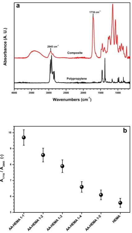
Figure 1 Schematic representation of membrane contactor: microporous, symmetric, hydrophobic/ hydrophilic membranes; P, pressure in each phase ... 1 Figure 2 Schematic representation of membrane distillation process ... 3 Figure 3 Different configurations of MD ... 4 Figure 4 Definition of contact angle: 90° < 𝜃 < 180°, hydrophobic surface (A); 0° < 𝜃 < 90°, hydrophilic surface (B) ... 6 Figure 5 General principle of membrane crystallizer: Cb , bulk concentration; Cm, concentration close to the membrane surface; J, transmembrane flux; K, phenomenological constant; ΔP, partial pressure gradient between two sides of membrane [10] ... 7 Figure 6 The energy barrier for nucleation. Gibbs free energy for crystallization (ΔG) as a function of the aggregate size (R), shown as an unbroken line. Contributions of surface formation and bulk incorporation are represented by broken lines. R* and ΔG* represent the size of the critical nucleus and the activation free energy (i.e., the energy barrier) for nucleation, respectively [26] ... 9 Figure 7 Volume phase transition in response to changes in surrounding conditions such as temperature, electric or magnetic fields, light, pH, solvent composition etc. [36] ... 13 Figure 8 Three integral parts of the hydrogels preparation [35] ... 14 Figure 9 Schematic illustration of different types of (a, b) pore-surface functionalization and (c) pore-filling [31] ... 15 Figure 10 The different monomers (AA, MAA and HEMA) and cross-linkers (EGDMA and PEGDMA) used in this work to fabricate hydrogel composite membranes ... 19 Figure 11 Experimental set up: UV/Vis irradiation lamp placed on the vented exposition chamber ... 21 Figure 12 Preparation of hydrogel composite membranes: 1) Pre-conditioning of membranes, 2) Preparing of hydrogel solutions, 3) Casting a thin layer of hydrogel solution, 4) Polymerization of the solution under the UV lamp ... 21 Figure 13 Characteristic SEM image of the top and cross section of AA-co-HEMA sample: A dense, uniform and defect-free hydrogel layer adheres to the surface of the porous PP support ... 24 Figure 14 UV-initiated polymerization reaction for the synthesis of the hydrogel layer on the PP support: AA /HEMA/EGDMA ... 25 Figure 15 Contact angle of Water for (a) virgin PP membrane and (b) hydrogel composite membranes .. 25 Figure 16 (a) Typical ATR-FTIR spectra of unmodified PP membrane and hydrogel composites. (b) Dependence of the FT-IR absorption signals ratio at 1700 and 3000 cm-1 (A1700/A3000) from the amount of AA (and carboxyl groups) in the hydrogel network structure ... 28
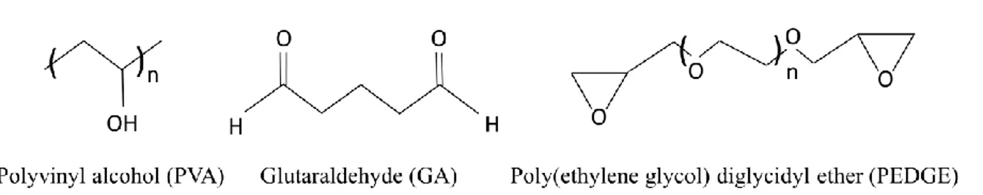
xii Figure 17 (a) Swelling degree SD of bulk-free hydrogel and gel layer in HCMs at20 °C in pure water and different NaCl solutions. (b) Ion exchange capacity IEC of HCMs at 20 °C. ... 30 Figure 18 Molecular structures of the polymer rand the cross-linkers used in this work to fabricate hydrogel composite membranes ... 35 Figure 19 Casting with the automatic film applicator adjusted at 50 µm thickness ... 37 Figure 20 Preparation of hydrogel composite membranes: 1) Pre-conditioning of membranes, 2) Preparing of hydrogel solutions, 3) Casting a thin layer of hydrogel solution, 4) Crosslinking reaction ... 37 Figure 21 DEKTAK Profilometer... 40 Figure 22 Surface patterning of HCMs constituted by a polyvinyl alcohol hydrogel layer with embedded iron oxide nanoparticles, supported on PP membrane (a) disordered and (b) aligned particles ... 40 Figure 23 Characteristic SEM image of the top and cross section of PVA-GA-NPs 1% supported on PP sample: A dense, uniform and defect-free hydrogel layer adheres to the surface of the porous PP support ... 41 Figure 24 Iron oxide particles detected by EDS on the surface and inside the hydrogel layer ... 41 Figure 25 Crosslinking reactions under catalytic condition for (a) PEDGE and (b) GA ... 42 Figure 26 ATR-FTIR spectra of unmodified PP membrane and PVA-GA-NPs supported on PP membrane ... 43 Figure 27 Three-dimensional images of studied surfaces a) PP membrane, b) PEDGE, c) PVA-PEDGE-INPs 0.25%, d) PVA-PVA-PEDGE-INPs 1%, e) PVA-GA, f) PVA-GA-INPs 0.25%, g) PVA-GA-INPs 1% ... 45 Figure 28 Laboratory plant of direct contact membrane distillation ... 51 Figure 29 Membrane distillation plant: T1–T6 temperature probes; P1–P2 pressure probes; FM1–FM2 flow-meters; PP1–PP3 peristaltic pumps; EV1–EV2 electro-valves; LV1– LV2 liquid-level probes; HE1– HE2 heat exchangers; PD1–PD2 pulsation dampers; and membrane holder cell (membrane module) ... 52 Figure 30 (a) Transmembrane flux J for pure water and NaCl 30 g L-1 solution and related solute rejection R, for virgin PP and composite hydrogel membranes. Horizontal dotted lines are guides for the eyes: they display the average flux with NaCl solution (down) and rejection to NaCl (up) for PP support. (b) Transmembrane flux J for NaCl solutions at different concentration and related solution rejection R, for AA-HEMA 1-1 composite. Horizontal dotted line is a guide for the eyes: it displays 100% rejection to NaCl. Error bars in the rejection points are smaller than the size of the symbols. ... 54 Figure 31 Rejection R and conductivity of the distillates with the time for MD tests with AA-co-HEMA 1-1 ... 55 Figure 32 Simplified description of the concentration and temperature profiles in composites [86] ... 58 Figure 33 Molecular structure of Glutamic acid ... 64
xiii Figure 34 Membrane-assisted crystallization device [86] used for the biomimetic synthesis of CaCO3. Hydrogel composite membrane is used to contact the CaCl2 solution and the compartment containing solid ammonium carbonate. Carbon dioxide comes from the spontaneous decomposition of the solid, goes through the porous composite membrane and reacts with Ca2+ in the gel layer, thus providing the formation of synthetic minerals ... 65 Figure 35 Crystals obtained by using different substrates: (a) virgin PP, (b) virgin PES, (c) HEMA/EGDMA, (d) AA/EGDMA, (e) MAA/EGDMA, (f, g) Mco-HEMA/PEGDMA, (h, I, j) AA-co-HEMA/PEGDMA, (k, l) AA-co-HEMA/EGDMA HCMs ... 66 Figure 36 Calcite rhombs obtained in the presence of poly acrylic acid [109] ... 67 Figure 37 SEM of calcium carbonate crystals grown in (a) agarose gel (b) alginate gel in the presence of AA, different morphology due to the interaction between hydroxyl groups and the carboxyl or amino groups [110] ... 67 Figure 38 CaCO3 crystal morphology in the presence of D, L ad DL-glutamic acid: HCMs supported on a) PP, b) PES membranes ... 68 Figure 39 Raman spectra of crystalline samples in the presence of D, L and DL glutamic acid ... 69 Figure 40 (a) Scatter plot of the response values estimated by the PLSR model (estimated Y values) versus those assigned in Table S3 (true Y values). Two groups of representative samples are highlighted, corresponding to rhombohedra and smooth crystals (group A), spherical and segmented crystals (group B); (b) Scatter plot of the weights of the second (LV2) versus the first (LV1) latent variables of the regression model. The distance of the representative points from the origin, highlighted by the two dashed lines, indicates the importance of the experimental conditions in explaining the data variance [75] ... 71 Figure 41. Representative Raman spectra of crystalline samples: (a) rhombohedral well-faceted crystals obtained with virgin PP and PES membranes and with HEMA HCMs; (b) rosette shaped polycrystalline structures; (c) marguerite shaped structures in the outside point; (d) marguerite shaped structures in the central part ... 73 Figure 42 Bidimensional evolution of CaCO3 spherulites grown at the gel/solution/air interface in a HCMs mineralization platform, operated at low supply rate of reactants (poly AA-co-HEMA/EGDMA 1–4 HCMs, PP support). Individuals at different stage of maturity are obtained in the same batch under slow mineralization kinetics. ... 74 Figure 43 Schematic illustration of protein molecules interaction with the surface of the meso-pores 3D nanotemplates; Some of the pores are expected to entrap the protein molecules, thus promoting nucleation and crystal growth [142] ... 77 Figure 44 Experimental membrane assisted crystallization set up: a droplet of the protein solution sits on the hydrogel composite membrane, provides the physical contact with the reservoir solution, so only
xiv volatile solvent migrates in vapor phase through the pores of the substrate (HCM) from crystallizing solution towards the stripping solution under the action of driving force, as the protein solution concentrates
inside the droplet, saturation allows nucleation and crystal growth [15] ... 80
Figure 45 Different HCMs have different surface energies and different topographies: (a) Contact angle and (b) Roughness for different HCMS as a function of the amount INPs in: PVA/GA HCMs (red) and PVA/PEDGE HCMs (blue). ... 82
Figure 46 Increasing nucleation probability (a) and number density of the crystals (b) by increasing the amount of INPs ... 83
Figure 47 Crystal images: (A) PVA-PEDGE (B) PVA-PEDGE-INPs 0.25% (C) PVA-PEDGE-INPs 1% (D) PVA-GA (E) PVA-GA-INPs 0.25%. (F) PVA-GA-INPs 1% ... 84
Figure 48 Geometry of a sphere-cap-shaped nucleating solution on a rough surface. ... 84
Figure 49 The ∆𝐺𝐻𝑒𝑡 ∗ ∆𝐺𝐻𝑂𝑀 ∗ratio as a function of the contact angle on different roughness [130].. 86
Figure 50 Crystal images: (a) PVA-GA-INPs 1%, (b) PVA-PEDGE-INPs 1% ... 86
Figure 51 Schema of direct contact membrane distillation: Cbf, bulk concentration and Cmf, concentration close to the membrane surface in the fid side; Tb, bulk temperature and Tmf, temperature close to the membrane surface in the feed side; Tp, bulk temperature and Tmp, temperature close to the membrane surface in the permeate side; J, transmembrane flux and Q, heat flux. ... 89
Figure 52 Differential volume element ∆𝑉𝑅 along the length of the module on the feed side and surface element ∆𝑆𝑚 on the membrane surface ... 98
Figure 53 Balanced element on the feed site ... 99
Figure 54 Balanced element on the membrane surface ... 102
Figure 55 Differential element ∆𝑉𝑅 along the length of the membrane module on the feed side ... 103
Figure 56 Component mass balance on the element ∆𝑉𝑝 ... 104
Figure 57 Component mass balance on the element ∆𝑉𝑠 ... 105
Figure 58 The electric analogy the mass transfer resistances ... 107
Figure 59 boundary layer on feed site ... 108
Figure 60 Boundary layer on permeate site ... 111
Figure 61 Component mass balance for the element ∆𝑉 on permeate site ... 112
Figure 62 Heat boundary layers: Tf, bulk temperature and Tmf, temperature close to the membrane surface in the feed side; Tp, bulk temperature and Tmp, temperature close to the membrane surface in the permeate side ... 114
Figure 63 Boundary layer for feed side ... 118
Figure 64 boundary layer for feed side ... 120
xv
Figure 66 Boundary layer for permeate side ... 125
Figure 67 Component balance on the tank ... 145
Figure 68 Covering the pore and solid part of membrane ... 148
Figure 69 Mass balance in pore volume ... 151
Figure 70 mass balance of a node for crystal removal ... 153
xvi
List of Abbreviations and Symbols
AA: acrylic acid
AGMD: air gap membrane distillation CA: contact angle
CNT: classical nucleation theory CSD: crystal size distribution
DCMD: direct contact membrane distillation DGM: dusty gas model
EGDMA: ethylene glycol dimethacrylate GA: glutaraldehyde
HCM: hydrogel composite membrane HEMA: 2-hydroxyethyl methacrylate HET: hetrogenous nucleation
HEWL: hen egg white lysozyme HOM: homogenous nucleation IEC: ion exchange capacity MAA: methacrylic acid MC: membrane contactor MCr: membrane crystallization MD: membrane distillation MF: microfiltration
MIP: molecularly imprinted polymers NF: nanofiltration
NPs: nanoparticles LEP; liquid pressure entry
PBE: population balance equation
PEDGE: poly (ethylene glycol) diglycidyl ether PEGDMA: polyethylene glycol dimethacrylate PES: polyether sulfone
PLSR: partial least square regression PP: polypropylene
xvii PVA: polyvinyl alcohol
PV: pervaporation RO: reverse osmosis
SGMD: sweeping gas membrane distillation UF: ultrafiltration
VMD: vacuum membrane distillation
θ: contact angle
: surface tension
γeff: effective nucleus/solution interface energy
ε: overall surface porosity
: activity coefficient
h: latent heat of vaporization μ: electrochemical potential τ: tortuosity factor υ0: molecular volume : electrical potential Ω: molar volume a: activity φ: volume factor
A: pre-exponential kinetic parameter Am: membrane area
Ahet: pre-exponential kinetic parameter for heterogeneous nucleation Ahom: pre-exponential kinetic parameter for homogeneous nucleation
C*: solubility
Cb: concentration in the bulk
Cm: concentration close to the membrane surface k
i
D : Knudsen diffusion coefficient G: crystal growth rate
ΔG: variation of the Gibbs free energy
Δp: vapor pressure gradient ΔT: temperature gradient
xviii
δ: thickness of the membrane j: trans-membrane flux kB: Boltzmann’s constant MW: molecular weight J: nucleation rate n: number of moles n*: critical size Na: Avogadro number p: partial pressure P: hydrostatic pressure
p0: vapor pressure of pure component
Pentry: entry pressure limit
R: gas constant r: curvature radius rp: pore radius rv,B: birth rate rv,D: dead rate rs*, D: transfer rate S: supersaturation T: absolute temperature t: time
Tcry: crystallization temperature
Tb: temperature in the bulk
Tm: temperature close to the membrane surface
Tp: temperature in permeate
tind: induction times
V: volume
W*: nucleation work
x: liquid mole fraction y: vapor mole fraction
1
Chapter I:
1
1.1. Membrane Contactors: An Introduction to the Technology
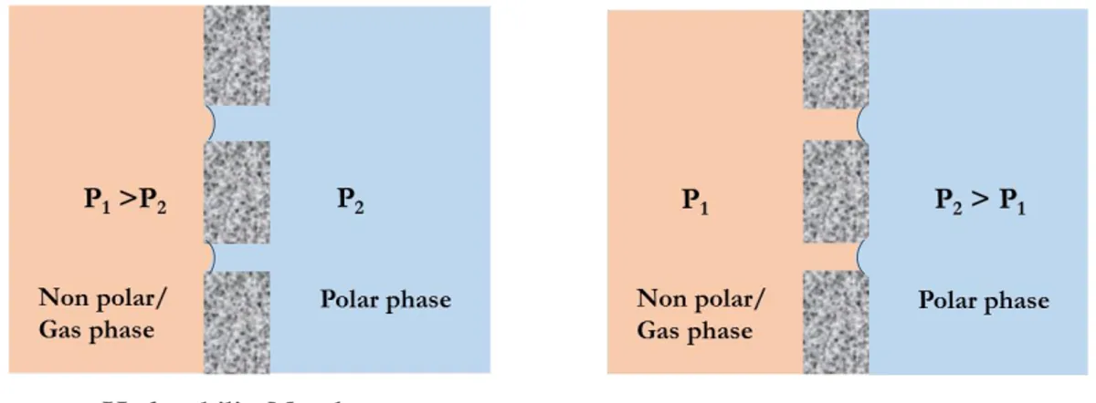
Membranes are frequently used in the industry as an easy and efficient tool for separation processes. Among the large variety of membrane operations, membrane contactors (MCs) are relatively new membrane-based devices, and because of their potential advantages, are gaining consideration both in industry and science fields. A membrane contactor is a device where separation of compounds is accomplished due to a specific driving force through the membrane from the one phase to the other on opposite sides [1, 2]. This module achieves gas/liquid or liquid/liquid mass transfer without dispersion of one phase within another (Figure 1). The membrane represents only an interface and can be defined as a perm-selective barrier between two homogenous phases and the mass transport is due to a diffusive process through the membrane pores from one phase to the other. All traditional stripping, scrubbing, absorption and liquid–liquid extraction operations, as well as emulsification and crystallization can be carried out according to this configuration [3].
Figure 1 Schematic representation of membrane contactor: microporous, symmetric, hydrophobic/ hydrophilic membranes; P, pressure in each phase
The performances of membrane contactors depend on the properties of the membranes used. In general, high hydrophobicity is required to prevent wetting and mixing between contacting phases; high overall porosity leads to high fluxes, but might cause bubble coalescence in gas/liquid operations. Fluxes also increase with pore size, whereas the breakthrough pressure (LEP)
2 decreases; a low thickness reduces the resistance to mass transport through the membrane, whereas, in membrane distillation, the amount of heat lost by conduction is increased. Despite the apparent operational complexity, considerable advantages offered by membrane contactor technology make these devices very useful in a range of liquid/liquid and gas/liquid applications such as fermentation, pharmaceuticals, wastewater treatment, semiconductor manufacturing, carbonation of beverages, metal ion extraction, protein extraction, VOC removal from waste gas, membrane distillation/ osmotic distillation and membrane crystallization [4].
1.2. Membrane Distillation Technology
Membrane distillation (MD) is an emerging membrane technology used for desalination of sea or brackish water, solution concentration, recovery of volatile compounds from aqueous solutions and other separation and purification processes [5, 6]. The term MD comes from the similarity of the MD process to conventional distillation as both technologies are based on the vapor/liquid equilibrium for separation and both require heat to be supplied to the feed solution to achieve the necessary latent heat of vaporization.
1.2.1. General Principle of Membrane Distillation
Membrane distillation refers to a thermally driven transport of vapor through non-wetted porous hydrophobic membranes, with the vapor pressure difference between the two sides of the membrane pores being the driving force. The feed side of the membrane is operated at hot temperature and the permeate side at cold temperature (Figure 2). When a microporous hydrophobic membrane separates two aqueous solutions at different temperatures, selective mass transfer across the membrane occurs: this process takes place at atmospheric pressure and at temperatures which may be much lower than the boiling point of the solutions. The hydrophobicity of the membrane prevents the transport of the liquid phase across the pores of the partition while water vapor can be transported across them from the warm side, condensing at the cold surface [7].
3
Figure 2 Schematic representation of membrane distillation process
1.2.2. Operational Configurations
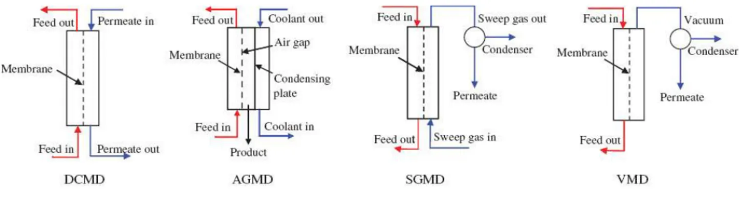
Membrane distillation may be operated in different configurations in which several possibilities are applied on the permeate side such as direct contact membrane distillation (DCMD), sweeping gas membrane distillation (SGMD), vacuum membrane distillation (VMD) and air gap membrane distillation (AGMD) as shown in Figure 3. All configurations have in common that liquid feed is maintained in direct contact with the hot side of the membrane without penetrating the pores. The difference between the configurations is found only in the permeate side [5]. In DCMD, the feed as well as the permeate side are aqueous solutions. The feed is maintained at hot temperature and the permeate at cold temperature giving rise to a transmembrane temperature difference which induces a vapor pressure difference. Consequently, volatile molecules evaporate at the hot liquid/vapor interface across the membrane towards the cold permeate side and condense in the cold liquid/vapor interface inside the membrane module. In SGMD a cold inert gas is applied on the permeate side which carries the vapor molecules and condensation occurs outside the membrane module. The VMD arrangement generally uses smaller pore sizes than the other MD configurations because vacuum is applied in this case and the risk of pore wetting is high. AGMD arrangement is used to considerably reduce the heat loss by conduction and temperature polarization, by placing an air gap inside the membrane module between the permeate side and the condensing surface [6].
4
Figure 3 Different configurations of MD
Direct contact membrane distillation is the simplest MD configuration, and is the most widely used in laboratory research. In this configuration, both the aqueous feed and permeate are in direct contact with the surface of a hydrophobic porous membrane and the temperature difference across the membrane provides the driving force to generate water flux. Like other membrane processes, the temperature and concentration polarization leads the temperature and concentration at the membrane surface to differ from the bulk temperature measured in the feed and in the distillate and performs as the heat and mass transfer resistance in the conventional membrane distillation. While, the highly-concentrated region near the hydrophobic porous membrane interface is an ideal nucleation promoting circumstance in the crystallization process. Compared with the ultrasonic accelerating and adding seeds technologies, the membrane process has more controllable operational parameters (temperatures and pressure of feed and permeate sides, membrane material, and area, and so forth), which increases the operability of supersaturation regulation. This reveals the general benefits and application potential of membrane process to industrial crystallization, especially the solution crystallization [8].
5
1.3. Membrane Crystallization Technology
Well-controlled crystallization is the best method for preparing materials that are uniform in shape, size, structure and purity. Crystal growth as well as nucleation depends on supersaturation degree. The local gradient of supersaturation sometimes acts as a limiting factor in respect to uniformity of the product quality. Membrane crystallization (MCr) is an innovative methodology to control the generation of supersaturation; and the use of MD technique in the concentration of a solution by solvent removal in the vapour phase is proposed for this new technology [9]. The first application of a membrane as a crystallizer dates to a few decades ago and to date several publications have been described the use of membrane crystallization technology and its advantages over conventional evaporative techniques. MCr, is today recognized as an innovative and efficient method for producing enhancing crystallization of organic/inorganic materials, by allowing the formation of crystals with reduced and uniform size with high purity as well as large and single crystals for biotechnological application and X-ray crystallography analysis [10-12]. The main features of MCr are: (1) the use of membranes as the physical support for mass transport in vapour phase, (2) the role of the porous surface of the membrane as suitable tool to activate heterogeneous nucleation mechanism, and (3) the possibility to induce nucleation and crystal growth in separate sites, thus reducing the risk of membrane fouling and pore blocking even when the membrane acts as heterogeneous nucleation support. These features represent a potential application of MCr in the field of controlled crystallization processes especially in the case of bio(macro)molecules like proteins [13-16]. Furthermore, MCr technology is expected to represent an attractive option for realizing integrated and highly efficient industrial productive processes, well satisfying the requirements of the process intensification strategy [17-19]. A significant example in this sense is seawater desalination, where a rational integration of MCr technology with traditional pressure-driven membrane operations, might determine substantial improvements in terms of water quality, product recovery factor, overall cost, environmental impact and brine disposal management. In addition, separation and recovery of minerals (i.e. NaCl, KCl and Na2CO3) with high purity as well as other compounds of high economic benefit (i.e. barium, strontium and lithium) from the seawater is another advantage of using MCr unit in the integrated desalination systems [20, 21]
6
1.3.1. Working principle of Membrane Crystallization
The general working principle of MCr can be considered as an extension of the membrane distillation or the osmotic membrane distillation, where diffusion of solvent molecules in vapour phase through a porous membrane, under a gradient of temperature or concentration as driving force, generates supersaturation in crystallizing solution. Supersaturation is driving force for crystallization which induce crystal nucleation and growth (Figure 5). According to this design, porous hydrophobic membranes are used to separate the crystallizing solution and the distillate solution. When the membrane is prevented to be wet from the adjacent solutions, no mass transfer through the membrane occurs in liquid phase. Wetting of the membrane, with the consequent deleterious direct passage of liquids, can be avoided when the pressure of the solutions facing it is lower than the liquid entry pressure (LEP), defined by the Young-Laplace’s equation [Atkin et al. 1993]:
𝑃𝑒𝑛𝑡𝑟𝑦 = −(2 σcos 𝜃)⁄ 𝑟𝑝 (1)
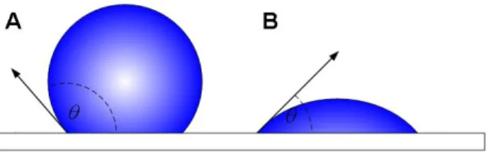
Where 𝜎 is the liquid surface tension, 𝜃 is the contact angle between the liquid crystallizing solution and the surface of membrane (Figure 4) and 𝑟𝑝 is the pore radius.
Figure 4 Definition of contact angle: 90° < 𝜃 < 180°, hydrophobic surface (A); 0° < 𝜃 < 90°, hydrophilic surface (B)
According to the equation above, for, 90° < 𝜃 < 180° , Pentry is positive. It means that hydrophobic membranes can be used for hydrophilic solutions and hydrophilic membrane are suitable for hydrophobic solutions. For a pressure, lower than Penry, the two liquids are stopped at
7 the entrance of each pore on both membrane sides, thus generating a curved profile as shown in Figure 5.
Figure 5 General principle of membrane crystallizer: Cb , bulk concentration; Cm, concentration close to the membrane surface; J, transmembrane flux; K, phenomenological constant; ΔP, partial pressure gradient between two sides of membrane [10]
In membrane crystallization, the membrane does not behave as a selective barrier, but it provides at the same time, the physical support for mass transport in vapour phase, thus generating supersaturation in crystallizing solution and the solid support to promote heterogeneous nucleation mechanism [10]. According to the classical nucleation theory (CNT), the nucleation rate 𝐽 [𝑚−3𝑠−1] for homogeneous nucleation can be expressed as [22]:
𝐽 = 𝐴 exp ( −𝐵 ln 𝑆2)
(2)
In this equation, 𝐴[𝑚−3𝑆−1] and 𝐵[𝑢𝑛𝑖𝑡𝑙𝑒𝑠𝑠] are kinetic parameters and 𝑆 is the supersaturation ratio. In the presence of a heterogeneous surface in the supersaturated solution, the apparent interfacial energy 𝛾 decreases. In this case, the nucleation barrier is smaller and heterogeneous nucleation will start at lower supersaturation level compared to homogeneous nucleation. For heterogeneous nucleation, the effective interfacial energy becomes, 𝛾𝑒𝑓𝑓 = ∅𝛾 with 0 < ∅ < 1, so that the term of 𝐵 in eq. 2 can be smaller than for homogeneous nucleation. In the case of an ideal smooth surface, volume function ∅, can be evaluated by:
8 ∅ =1
4(2 + cos 𝜃)(1 − cos 𝜃)
2 (3)
Where, 𝜃 is the contact angle between the crystalizing solution and the membrane surface. In the case of heterogeneous nucleation induced by a porous membrane surface, this equation can be used: ∅𝑝𝑜𝑟 = 1 4(2 + cos 𝜃)(1 − cos 𝜃) 2[1 − 𝜀(1 + cos 𝜃) 2 (1 − cos 𝜃)2] 3 (4)
With 𝜀 is the surface porosity [23].
1.3.2. Control of Supersaturation by means of Membrane
Supersaturation is the driving force for crystallization and the rates of nucleation and crystal growth depend on it. By choosing a suitable membrane and operating conditions, the extent of the crystalline population (crystal size distribution (CSD)), the crystals morphology (size, habit and shape) and structure properties as well as purity can be properly controlled. The fine control of the transmembrane flux and its effect on crystallization has been studied by membrane assisted crystallization processes. Generally, in MCr systems, the variation of the “thermodynamic parameters” such as temperature, concentration, flow rate and etc. in the direction of decreasing flux, produces at the same time a decrease of supersaturation generation rate by solvent removal, with the consequent tendency towards an extension of induction time but also a decrease of solubility which lead to the increase of supersaturation. Induction time is defined as time between the microdroplet deposition and the appearance of the first crystal. As induction time is inversely proportional to nucleation rate, it means that crystals are simulated to appear earlier and nucleation is accelerated. Accordingly, a parabolic behavior is usually observed in the curves displaying the relation between induction time and one of the thermodynamic parameters, due to the competition of the two forces on the overall process. When only “kinetic parameters” are varied in the direction of increasing the trans-membrane flux, supersaturation generation rate increases as well, and crystals are proven to nucleate faster due to the rapid establishment of a high level of supersaturation [24]. Control of trans-membrane flux in a membrane crystallization also has an
9 influence on the purity of the obtained crystals. Generally, high local supersaturation which generates a growth rate higher than that critical threshold value (which separates regions of impurity inclusion development and the growth of purer crystals), can reduce the crystal purity [25].
1.3.3. Heterogeneous Nucleation on the Membrane Surface
To create an environment that favors nucleation the use of solid templates (nucleants) has become a common practice.Such nucleants could help to enhance the chances of any single trial producing crystalline material thus reducing the initial concentration used for screening and/or to increase the nucleation rate, with consequent effect on crystal size and size distribution. In the nucleant-assisted interaction among the solute molecules, the surface will support the proper molecular orientation thus leading to the formation of crystalline clusters with well-ordered organization of the building blocks [26]. Furthermore, substrate-molecule interactions would reduce the surface tension of the growth units and hence will lower the activation energy for nucleation, allowing the crystallization to occur in that conditions which would not be adequate for spontaneous nucleation [13]; This effect is termed heterogeneous nucleation, the process by which the surface of a foreign material lowers the nucleation barrier and facilitate aggregation in that conditions which would not be adequate for spontaneous (homogeneous) nucleation [27].
Figure 6 The energy barrier for nucleation. Gibbs free energy for crystallization (ΔG) as a function of the aggregate size (R), shown as an unbroken line. Contributions of surface formation and bulk incorporation are represented by broken lines. R* and ΔG* represent the size of the critical nucleus and the activation free energy (i.e., the energy barrier) for nucleation, respectively [26]
10 A first reason for the attractiveness of heterogeneous nucleation for crystal growers is that nucleation induced at lower degree of supersaturation can occur inside the metastable zone. Because growth in the metastable zone affords kinetic advantages that often lead to the production of larger and better-ordered crystals than those grown at higher supersaturation, an aim of crystallizers is the possibility to induce heterogeneous nucleation in a controlled manner. In a membrane crystallizer, the crystallizing solution is in direct contact with the membrane surface, and the membrane provides the solid support to promote heterogeneous nucleation mechanism in addition to good control of the supersaturation rate by solvent removal through its porous structure. This effect can be due to both the structural and chemical properties of the membrane surface. The porous membrane can supply cavities where solutes are physically entrapped leading, locally, to high super saturation values suitable for nucleation and also the interaction between the membrane and solute can allow to concentrate and orient molecules on the surface, thus facilitating effective interaction for crystallization [14]. Membrane surface promotes heterogeneous nucleation not only by lowering energy of aggregating but also by structural matching driven by specific polymer molecules interfacial interaction per a mechanism analogue to epitaxial growth. Capability of polymorph selection, kinetically driven by the preferential aggregation of molecules along specific crystalline facets, corroborates these assumptions [28]
1.3.4. Operational Configurations
The specific mechanisms for mass transport depends on the operational configuration of the membrane crystallizer. Two configurations exist: (i) Solvent evaporation membrane crystallizer where solvent is removed in vapor phase under the gradient of temperature or concentration and (ii) Anti-solvent membrane crystallizer which an anti-solvent is dosed inside the crystallizing solution by means of membrane and the mass transfer occurs by evaporation as well. In Solvent evaporation membrane crystallizer configuration, the distillate side of the membrane consists in a condensing fluid (often the pure solvent) at a lower temperature than the feed side in the case of thermal activation of the driving force, or in a stripping solution consisting in a hypertonic solution of inert salts (NaCl, MgCl2, CaCl2, etc.) in the case of the isothermal configuration. The gradient of chemical potential between the two sides of the membrane induces
11 the evaporation of the solvent at the first interface on the feed side, then the migration of the solvent in vapor phase through the porous membrane and finally, its condensation at the second interface on the distillate side. The continuous removal of solvent from the feed solutions increases solute concentration thus generating supersaturation. Like other membrane process, the temperature and concentration polarization leads the temperature and concentration at the membrane surface to differ from the bulk temperature measured in the feed and in the distillate. Both concentration and temperature polarization nearby the membrane surface might affect locally the degree of supersaturation, so that the mechanism of crystallization can develop in a different way with respect to the bulk of the solution. The highly concentrated region near the porous membrane interface is an ideal nucleation promoting circumstance in the crystallization process. Accordingly, the properties of the crystal nucleated and grown on/near the membrane might display characteristics features that can be controlled by modulating the heat and mass profiles adjacent to the membrane. While in the case of inorganic substances or low molecular weight organic compounds, the thermal system can be affectively used, for the heat-sensitive molecules, like proteins, the osmotic configuration appears more appropriate because of its milder operating conditions. In the antisolvent membrane configuration, two configurations exist: (a) solvent/ antisolvent demixing configuration and antisolvent addition configuration. In the solvent/antisolvent demixing configuration, a solute is dissolved in an appropriate mix of a solvent and antisolvent. Under a gradient of chemical potential which is generated by temperature difference between both sides of the membrane, the solvent evaporates at higher flow rate. As the amount of solvent decreases, supersaturation is created. This configuration requires that the solvent and the antisolvent are miscible, the solvent evaporate at higher rate than the antisolvent and the initial solvent/antisolvent balance in the mixture guarantees that the solute is under its solubility limit. In antisolvent addition configuration, a solute is dissolved in a solvent and under a gradient of chemical potential, an antisolvent is gradually evaporated from other side of the membrane. The antisolvent mix with the solvent, then the solute dilute. At the certain time, the excess of antisolvent creates supersaturation. For this configuration is also required that the solvent and the antisolvent are miscible. In this study, the employed membrane configuration is solvent evaporation membrane crystallizer [5].
12
1.4. Membranes for Membrane Contactor
The membranes for membrane contactor application must be porous, generally hydrophobic, with good thermal stability and excellent chemical resistance to feed solutions. One of the most crucial aspects of the membrane distillation and membrane crystallization process is to have at disposal membranes with well controlled properties. Moreover, the final performance of a process is a direct consequence of the structural and physicochemical properties of the membranes. In this regards, development of well-structured and functionalized membranes becomes an imperative [2, 4]. Traditionally, the membranes prepared for ultrafiltration and microfiltration through phase inversion processes have been utilized for membrane contactor applications.These membranes generally have low porosity, limited hydrophobicity, broader pore size distribution and pore size not engineered for MD requirements. Therefore, many studies have been dedicated in the last years to fabricate innovative membranes of highly permeable and more selective membranes with low fouling and wetting aptitude for MD applications [5, 29, 30]. In addition, in MCr application, because of the role of membrane surface properties on heterogeneous nucleation, and to create a suitable environment that favors nucleation of the solutes, surface functionalization becomes more important. Therefore, since performances of membranes also depend on the properties of their surfaces, much attention has been paid to the membrane surface modification as an alternative method to improve the performance of membranes. In general, the major aim of surface modification is improving the performance of the membranes with a view to altering a wide range of characteristics of the surface, such as roughness, surface charge, hydrophilicity/hydrophobicity, biocompatibility, and functionality without changing the bulk properties of the membranes. In this respect, the combination of functional materials and membranes as a support might offer beneficial synergisms that endow the resulting composite membranes with entirely novel separation functions for membrane contactor, compared to the commercial membranes [31]. In this work, functional hydrogel materials were studied and selected to fabricate and develop the novel composite membranes with proper properties for application in membrane distillation and membrane crystallization processes.
13
1.5. Hydrogel Composite Membranes
Nowadays, hydrogel materials have attracted vast attention because of their novel properties and high potential as functional materials. Hydrogels are defined as porous cross linked polymeric structures capable to swell in water and adjust their dimensions and some other properties such as water content, porosity, and capacity to retain or release substances entrapped between the chains, according to the surrounding environment [32, 33]. Principally, these materials have three-dimensional network with ionic or covalent cross links, and hydrogen bonding and van der Waals forces can also act as cross links. In general, the cohesive forces are not only due to covalent bonds (chemical hydrogels) but can also be related to electrostatic forces or dipole-dipole links (physical hydrogels). However, it is important to consider that the swelling/deswelling behavior of hydrogels depends on the nature of the polymer, the polymer-solvent compatibility and the degree of crosslinking [34]. Volume phase transition is a peculiar phenomenon observed with these materials (Figure 7). At the transition, the volume of a hydrogel changes discontinuously in response to continuous changes in surrounding conditions such as temperature, pH, electric or magnetic fields, light and solvent [35-39].
Figure 7 Volume phase transition in response to changes in surrounding conditions such as temperature, electric or magnetic fields, light, pH, solvent composition etc. [36]
Since the volume phase transition brings about dramatic changes in physical properties of the gel, this effect is expected to be applied to the preparation of switching functional materials.
14 Because of this specific feature, the fabrication and study of novel hydrogel have been intense because of their promise and use in a different branch of science and engineering [40]. Furthermore, hydrogel materials due to their tunable physical and chemical properties and versatility in fabrication, have recently emerged as advanced materials in the field of separation and membrane processes.The separation function of these hydrogel arises from two important features, the 3D network of hydrogels having a tunable mesh size in nanometer range and thus imposing exclusion of molecules based on size or charge [41, 42] and stimuli responsive behavior that can have an additional impact on the separation when sieving is adjusted using external stimuli. Transport through hydrogels, especially under convective flow condition is only possible when the gel is stabilized by a solid support to maintain its integrity. Consequently, hydrogels intended for separation applications should be fabricated in a suited format in order to control swelling without compression under convective flow and with ease of handling.One promising approach is combination of hydrogels and porous membranes as support that leads to composites structures. This is primarily achieved through the synthesis of a hydrogel either inside the pores of a support, thus obtaining a pore-filling composite or on the outer surface of a support, resulting in a thin-film composite membrane [31]. In this sense, hydrogel used in hybrid materials, would provide striking potentialities to accomplish advanced separation because of multi-scale and hierarchical porous structure that is achievable by the hydrogel/support composites synergism. As a hydrogel is simply a hydrophilic polymeric network cross-linked, it can be prepared by any polymerization technique which can be used to create a cross-linked polymer, including bulk solution and suspension polymerization. In general, the three integral parts of the hydrogels preparation are monomer, initiator and cross linker as shown in Figure 8.
15 To control the heat of polymerization and the final hydrogels properties, diluents can be used, such as water or other aqueous solutions. The structural diversity of the hydrogels is based on the use of a wide range of synthetic monomers, but biopolymers or their derivatives can also be applied. To date, different techniques have been established for incorporation of hydrogel materials into porous membranes, i.e. various surface grafting methods, pore filling and combination thereof as shown in Figure 9.
Figure 9 Schematic illustration of different types of (a, b) pore-surface functionalization and (c) pore-filling [31]
In surface grafting method, monomers are polymerized via initiation of the membrane surface and for initiation of the polymerization reaction, different methods can be used such as plasma treatment, high energy irradiation, redox initiation and UV irradiation. Among these methods, UV initiated grafting of hydrogel onto a micro or macro porous support has a much interest due to low cost of operation, mild reaction conditions, and potential for reducing or even avoiding negative effects onto the bulk polymer [43-45]. Composite hydrogel membranes have been prepared by different methods for ultrafiltration (UF) [46-48], nanofiltration (NF) [49, 50], reverse osmosis (RO) [51], and pervaporation (PV) [52] in liquid separations, with significant improvements in either selectivity and/or permeability. The only use of hydrogel composites in membrane distillation is related to the covering of commercial Teflon membranes by with a pre-formed agarose hydrogel layers with the aim to mitigate wetting effects in surfactants and dyeing wastewaters treatment which has been recently reported [53].
16
Chapter II:
Development of Hydrogel Composite Membranes
Preparation and Characterization
17
2.1. Polyelectrolyte Hydrogel Composite Membranes with Stimuli Responsive Behavior
2.1.1. Introduction
Hydrogels are three-dimensional network of polymer chains which are physically and/or chemically cross-linked. Generally, they are soft, flexible, with low surface friction and can absorb and retain large amount of water without dissolution [33]. Because of their permeable structure with not-well-defined pores, hydrogels can play separation functions by imposing exclusion based on molecular size [41, 42]. As they can be designed to adapt their swelling state in response to externally applied stimuli, such as temperature [35, 36], pH and ionic strength [37], electric or magnetic fields [38, 54], light [39], and interaction with specifics molecules [55, 56], additional control over separation mechanism is achievable under specific conditions. Furthermore, polyelectrolyte hydrogel layer can be attained using a charged/polarizable monomer and/or cross-linker in the hydrogel synthesis, so that, more than steric hindrance effects, transport selectivity would be driven by the electrical charge features of the gel network as well [57, 58]. Transport through hydrogels, especially under convective flow condition is only possible when the hydrogel is stabilized by a solid support so that it can maintain its integrity. Consequently, hydrogels intended for separation applications should be fabricated in a suited format to control their swelling/shrinking, without compression under convective flow, and to be easy to handle. One promising approach is the combination of hydrogel materials and porous membranes used as support [31]. When such hydrogel materials are supported on the porous membranes (due to enhance their mechanical properties), novel functional membranes with adjustable functionalities compared to the virgin membrane or bulk hydrogel are obtained. These hydrogel-based hybrid materials could provide novel potentialities to accomplish advanced separations thank to the synergistic combination between the hydrogel and the support [59]. Since the stimuli responsive changes in membrane properties will depend primary on the barrier itself, a change in the swelling/shrinking of the barrier leads to changes in permeability and selectivity. In this study, we prepared various polyelectrolyte hydrogel composite membranes (HCMs) directly synthesized on the surface of porous polypropylene (PP) and polyether sulfone (PES) flat sheet membranes using UV initiated graft polymerization technique. Commercial PP and PES membranes were chosen as support material due to high porosity, excellent chemical and mechanical stability, also their accessibility. Acrylic acid (AA), metacrylic acid (MAA) and 2-hydroxyethylmethacrylate
18 (HEMA) used as functional monomers, provide carboxyl (-COOH) and hydroxyl (-OH) groups. In particular, in our experiments, we have selected these functional monomers, because the presence of ionizable groups and their potential for preparing pH and ionic strength sensitive hydrogel system has been reported [60]. Moreover, formation of these hydrogel layer on the polymeric membranes is also possible. Ethylene glycol dimethacrylate (EGDMA) and Polyethylene glycol dimethacrylate (PEGDMA) were used as cross-linkers. Changes in the molar ratio between monomer(s) and cross-linker in the hydrogel synthesis, allowed modulating the ratio of hydrophilic to hydrophobic segments and the density of functional groups (the overall dissociation degree and charge density) in the polyelectrolyte hydrogel network. The resulting composite membranes were characterized by electron scanning microscopy, surface chemistry analysis (FTIR-ATR spectrometer), water contact angle, and ion exchange capacity and swelling degree measurements. As a result, a self-sustaining composite material with multi-scale porous structure, containing hydrogel mesh size in the nanometers range and porous support with pore size in the order of few hundreds of nanometers were obtained. These polyelectrolyte hydrogels displayed a volume phase transition property in response to the salt solution as stimulus as well. This responsive behaviour is related to the presence of hydroxyl and carboxyl groups in the hydrogel networks which causes to swelling/shrinking behaviour of them in response to the salt solution. Potential applications of such hydrogel composite membranes in membrane distillation as gating device because of the ionic strength-responsive behavior of the gel layer to obtain higher water flux, higher solute rejection and long-term stability and also in biomimetic synthesis of CaCO3 superstructures because of the favorable interaction of the acidic groups with molecules of solute to control the crystal morphology are discussed in the chapter Ш.
19
2.1.2. Materials
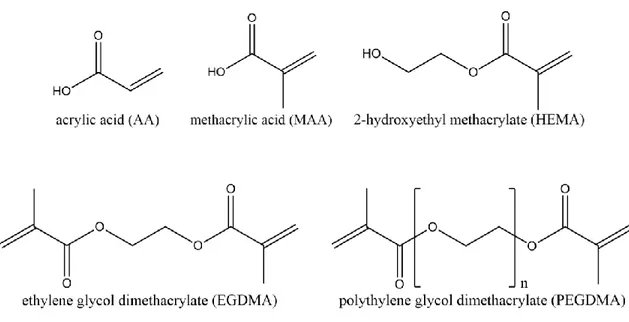
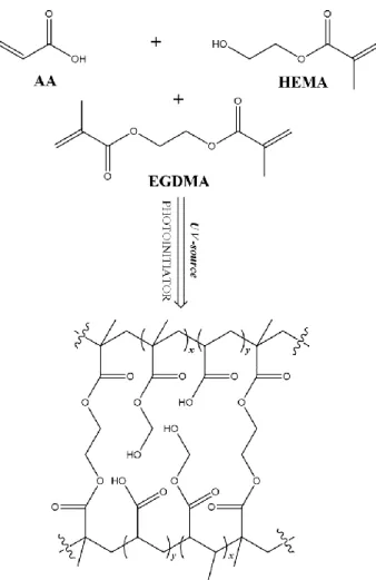
Two commercial membranes: polypropylene flat sheet membranes (Accurel PP 2E HF, and poly ether sulfone (PES) flat sheet membranes (Micro PES 2F) were purchased from Membrana GmbH (Wuppertal, Germany). Acrylic acid (AA, monomer, cod.101302902), metacrylic acid (MAA, monomer, cod. 155721), 2-hydroxyethylmethacrylate (HEMA, monomer, cod.101095911), ethyleneglycoldimethacrylate (EGDMA, cross-linker, cod.1012880077), polyethylene glycol dimethacrylate (PEGDMA, average Mn. 750 Da, cross-linker, cod. 437468), 2-hydroxy-2-methyl propiophenone (photoinitiator, cod.1001451059), were obtained from Sigma Aldrich. The molecular structure of the monomers is shown in Figure 10. Sodium chloride (cod.131659.1211) was from Panreac (Nova Chimica, taly) and methanol was from Sigma Aldrich. All chemicals were used as received and water purified with a Milli-Q system was used for all experiments.
Figure 10 The different monomers (AA, MAA and HEMA) and cross-linkers (EGDMA and PEGDMA) used in this work to fabricate hydrogel composite membranes
20
2.1.3. Hydrogel composite membranes preparation
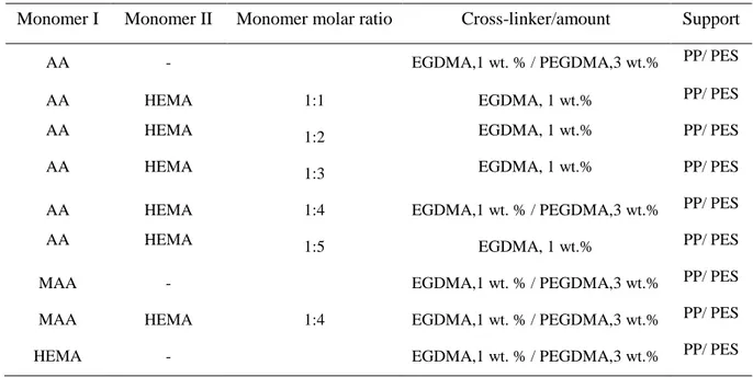
The polypropylene and the polyether sulfone membranes were conditioned by soaking in methanol and pure water respectively for 24 h at room temperature. Thereafter, the samples were taken out and dried between tissue paper before use. The hydrogel solutions (pre-polymerization solutions) were prepared by dissolving the accurate amount of monomer(s) in a known amount of pure water, followed by adding the cross-linker and the photo-initiator respectively. The compositions of the monomer solutions used for this study are listed in Table 1.
Table 1 Composition of the monomer solutions for preparation of HCMs
Monomer I Monomer II Monomer molar ratio Cross-linker/amount Support
AA - EGDMA,1 wt. % / PEGDMA,3 wt.% PP/ PES
AA HEMA 1:1 EGDMA, 1 wt.% PP/ PES
AA HEMA 1:2 EGDMA, 1 wt.% PP/ PES
AA HEMA 1:3 EGDMA, 1 wt.% PP/ PES
AA HEMA 1:4 EGDMA,1 wt. % / PEGDMA,3 wt.% PP/ PES
AA HEMA 1:5 EGDMA, 1 wt.% PP/ PES
MAA - EGDMA,1 wt. % / PEGDMA,3 wt.% PP/ PES
MAA HEMA 1:4 EGDMA,1 wt. % / PEGDMA,3 wt.% PP/ PES
HEMA - EGDMA,1 wt. % / PEGDMA,3 wt.% PP/ PES
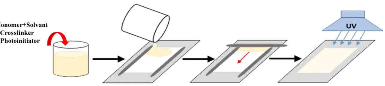
The solutions were magnetically stirred until complete dissolution and then free standing hydrogel were prepared from the reaction mixtures. The solute concentration was gradually increased to achieve stable and manageable gels. The solution then was cast onto the PP and PES membranes by rolling on the loaded support with a bar coater at 100 µm thickness. Photo-initiated graft polymerization was carried out under an UV/Vis irradiation lamp (GR. E. 500W) in a vented exposition chamber (Helios Italquartz, Italy), for 5 min. Experimental set up is shown in Figure 11.
21
Figure 11 Experimental set up: UV/Vis irradiation lamp placed on the vented exposition chamber
Thereafter, the prepared hydrogel composite membranes were washed and stored in a large excess of distilled water at room temperature for further characterization and experiments. Schematic illustration of the preparation procedure of HCMs is shown in Figure 12.
Figure 12 Preparation of hydrogel composite membranes: 1) Pre-conditioning of membranes, 2) Preparing of hydrogel solutions, 3) Casting a thin layer of hydrogel solution, 4) Polymerization of the solution under the UV lamp
2.1.4. Hydrogel Composite Membrane Characterization
2.1.4.1. Surface morphology analysis
Morphological analysis (top and cross section) of hydrogel composites was performed by a Quanta 200F FEI Philips scanning electron microscope (SEM). Samples were cut and attached