IEEE ANTENNAS AND WIRELESS PROPAGATION LETTERS, VOL. 7, 2008 5
Meandered-Slot Antennas for Sensor-RFID Tags
Claudio Calabrese and Gaetano Marrocco, Member, IEEE
Abstract—This letter introduces a planar antenna layout suited to Sensor-RFID fabrication. The geometry is based on a mean-dered-slot profile on a suspended patch and permits to host sensors and electronics in a small space. The available geometrical param-eters are optimized by means of a Genetic Algorithm (GA) proce-dure aimed to maximize the antenna realized gain. The antenna performances are discussed through examples and prototypes.
Index Terms—Genetic algorithm (GA), miniaturization, radio frequency identification (RFID), sensor, slot-line.
I. INTRODUCTION
O
NE of the most fascinating evolutions of the Radio Fre-quency IDentification (RFID) technology is the Sensor RFID family (S-RFID) where the tag is augmented with sensing and signal processing capabilities in addition to more traditional labelling operations [1]. Some applications have been already envisaged such as the monitoring of environmental parameters as well as of the human activity (temperature, blood pressure, heartbeat, glucose content, motion) [2], [3]. Such devices re-quire a higher degree of integration when compared with stan-dard RFID tags, since the antenna, the chip (IC), and all the rel-evant sensing electronics need to be efficiently packaged within a small space.In a recent paper [4], a versatile tag antenna configuration, having impedance tuning capability and the possibility to host electronics packaging, has been proposed for application in biomonitoring. The antenna consists of a nested H-slot suspended patch, wherein the external size determines the maximum gain while the H-aspect ratio affects the complex impedance matching. This layout is now generalized by in-troducing a larger number of design parameters so that, when properly optimized, the antenna could permit to fulfill several electrical and geometrical constraints, such as the impedance matching to a particular IC, the integration of a given size sensor, the space miniaturization, and a stable response over a large variety of tagged dielectrics and multiband performances.
II. ANTENNALAYOUT
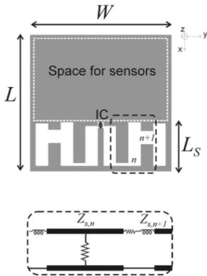
The considered antenna layout (Fig. 1) comprises a planar patch (with no ground plane) provided with a nonuniform slot-line which occupies just a portion of the metallization. The choice of the slot, as main radiating element, is expected
Manuscript received September 22, 2007; revised November 27, 2007. The authors are with the Dipartimento di Informatica, Sistemi e Produzione, Università di Roma Tor Vergata, 00133 Rome, Italy (e-mail: marrocco@disp. uniroma2.it).
Digital Object Identifier 10.1109/LAWP.2007.914123
Fig. 1. General layout of the proposed tag family and distributed model of the slot-line sections including radiation from step discontinuity (shunt conductance).
to simplify the synthesis of the inductive reactance required to match the generally capacitive IC’s impedance.
As discussed in [4], the H-slot may radiate, depending on the slot’s aspect ratio, as a broadband patch, a doubly folded dipole or as a dumbbell slot.
By generalization of the circuit model of the dumbbell slot in [5], it can be assumed that each short slot-line section mainly provides electric energy storage and radiation, while the discontinuity (tooth) between two slot-lines having different section adds an inductive reactance besides producing radiation. The whole slot profile, hereafter denoted to as Meander-Slot Antenna (MSA) can be, therefore, considered as a slot-line impedance transformer, with many degrees of freedom to convert the terminating short circuit to the complex conjugate of the IC impedance.
III. OPTIMIZATIONPROBLEM
The antenna’s shape optimization problem can be cast as the selection of the geometrical profile of the slot-line transformer, under sensor space constraints, such to achieve the maximum activation distance of the RFID tag, when it is placed onto a particular dielectric object.
Having fixed the effective power EIRP transmitted by the reader and the sensitivity of the tag’s IC (i.e., the RF
6 IEEE ANTENNAS AND WIRELESS PROPAGATION LETTERS, VOL. 7, 2008
Fig. 2. Geometric parameters of the slot-line tag to be optimized, for the par-ticular case of2N = 6 (three independent teeth). Only half of the antenna layout is shown.
power required to the microchip electronics to turn on and to perform backscattering modulation), the maximum activation distance of the tag is given [6] by
EIRP
(1) where is the maximum tag’s gain, and the factor
(2) is the power transmission coefficient which accounts for the impedance mismatch between the antenna
and the chip . The ultimate antenna’s
feature to be maximized is, therefore, the realized gain . To reduce the design complexity, the shaped slot is assumed to be symmetric with respect to the -plane. The geometrical constraints are: tag’s external size , slot-over-tag ratio , depending on the space to allocate sensors, and the number of slot’s teeth. The parameters to optimize are (see Fig. 2) the position of the chip and the vertical exten-sion of the independent teeth given in terms of their upper
and lower coordinates . The length of
each slot-line section is instead regular and fixed by the teeth’s number and the size. The teeth’s coordinates are subjected to some constraints for geometrical consistency, e.g.
(3) where is a safeguard distance from the patch edges.
The fitness function to maximize is
(4)
where are the frequencies at which the RFID should be best matched to the chip, and are arbitrary weights.
The optimization problem is solved using a Genetic Algo-rithm (GA) [7] procedure, already successfully applied to me-ander-line tag design [8]. To simplify the electromagnetic com-putation, required to calculate the gain and the impedance of each antenna of the GA population in presence of the tagged
body, a canonical reference geometry is assumed for the target, consisting of a homogeneous dielectric slab, of permittivity , orthogonal to the axis and bounded within . The tag is placed on . Configurations with represent the free space and hence is useful to model a tag sensing some en-vironmental parameters, such as humidity or temperature. The limiting case with (half-space) could instead model large and deep targets, such as walls or containers. Intermediate thickness could account for the tag response over finite objects like pallets or blood sacs. The evaluation of the fitness in (4) for each antenna of the GA population is accomplished by a planar Moment Method solver [9], using Sommerfeld integral to model the dielectric slab.
IV. DESIGNEXAMPLES
Some design examples at single and dual frequency, are here reported for an RFID chip having high-angle-phase impedance (which represents one of the most chal-lenging matching condition). All the presented results have been obtained by the GA procedure using 4 bit coding of the
geometrical parameters to optimize.
A. Tag Miniaturization
A first design set is useful to discuss the miniaturization fea-ture of the proposed layout respect to the slot size, to the number of teeth and to the permittivity of the dielectric target. The pro-posed examples will also suggest a guideline to fix some geo-metrical parameters. All the reported designs refer to a square tag of size 5 5 cm (corresponding to in the free-space), IC packaging’s size 2 2 mm and frequency
(European RFID UHF frequency).
The performance of the GA-optimized multitooth antennas can be appreciated in comparison with those of the simple H-shaped slot (single tooth, ) described in [4].
Fig. 3 shows some optimized geometries for the case of an homogeneous half-space target with permittivity and some different constraints on the slot size, expressed as frac-tion of the external tag size. The single-tooth antenna is not adequate to achieve a reasonable impedance matching , even if the slot occupies half of the available space, while a nearly unitary power transfer coefficient can be obtained by using 5-9 teeth even when the slot size is constrained to 2/5 the overall tag size. In this case, a larger number of teeth are re-quired and the antenna geometry becomes however more com-plex and more sensitive to fabrication’s imperfections. The re-sulting shaped slot profile resembles that of a meander-line an-tenna which is a typical miniaturized tag geometry [8].
Further designs results are summarized in Table I for other choices of target’s thickness and permittivity. The best tag having the simple H-slot profile , optimized for the free space, is such that the slot extends all over the available tag size without any miniaturization. In spite of the resulting large slot, the tag has a modest power transmission
coefficient and realized gain . A
relevant slot miniaturization, moreover preserving a -dipole like gain, can be instead achieved by multitooth configurations
CALABRESE AND MARROCCO: MSAS FOR SENSOR-RFID TAGS 7
Fig. 3. Examples of MSA tags with sizeL = W = 5 cm, placed over an " = 3 dielectric half-space. The slot-line profile has been optimized for an IC withZ = 150 j450 , for different sizes L of the antenna region and for different numberN of independent slot-line sections. G is the maximum gain in the air half-space(z < 0).
TABLE I
PERFORMANCES OFMSA TAGOPTIMIZED FORDIFFERENTTARGET’S
THICKNESS ANDPERMITTIVITY
Performances similar to the case have been also ob-tained for configurations but in these case the gain re-duces in the air since the maximum radiation occurs toward the dielectric half-space. The table also reports some design for fi-nite-thickness targets ( , 20 cm) and even in this case a nice impedance matching is observed.
Finally, the power transmission factor has been computed for several optimized antennas over homogeneous half space with an increasing number of teeth. In all the considered con-figurations (Fig. 4) a saturation effect is clearly apparent. The ( , , ) diagrams offer some guidelines to choose the number of the teeth depending on the target’s permittivity and on the space to allocate sensors and electronics. The improve-ment of the parameter along with is nearly linear in the first region of the curves, then after a knee-point, which reduces for smaller slot occupancy, the further increases of are less relevant. The knee-points, indicated by a marker in the figure, could be a reasonable choice for , as tradeoff between a nice impedance matching and fabrication complexity.
B. Dual-Frequency Tag
The GA optimization has been here applied to the design of
a dual-band MSA tag working at (RFID UHF
Fig. 4. Best achieved power transmission coefficient with respect to the number of teeth used in the slot profile optimization. Circles indicate the approximate transition from the linear improvement of , along with N , to saturation. The target is a homogenous half-space.
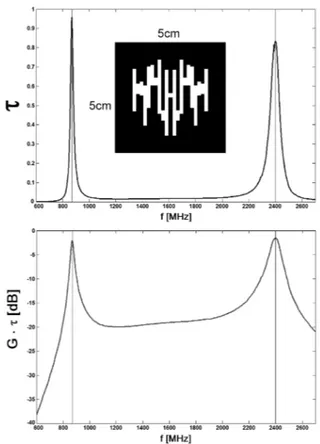
Fig. 5. Layout of dual frequency tag, optimized for dielectric half-space with " = 3.
frequency) and (RFID microwave frequency). The fitness function in (4) is maximized for the choice . No space requirement has been enforced over the slot, which is now allowed to occupy the whole tag size.
Results in Fig. 5, referring to a 5 cm 5 cm tag having teeth and placed over a half-space, shows nearly identical values of realized gain at the two considered frequencies.
8 IEEE ANTENNAS AND WIRELESS PROPAGATION LETTERS, VOL. 7, 2008
Fig. 6. (Top) Free-space tag with sizeL = W = 5 cm, number of teeth 2N = 40, fabricated onto an FR4 board. (Bottom) Tag connected to a choked coaxial cable for input impedance measurements.
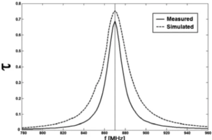
Fig. 7. Power transmission coefficient of the prototype in Fig. 6, measured and simulated in the RFID frequency band of 870–960 MHz.
V. EXPERIMENTALEVALUATION
An 870-MHz MSA tag prototype (Fig. 6) for free-space appli-cations was fabricated on FR4 substrate ( , ), wherein the slot occupies half of the tag’s space. To characterize the tag independently on the microchip and on the reader’s features, the antenna’s input impedance was di-rectly measured in chipless mode, and a semirigid coaxial cable was just connected to the central slot (where the IC should be placed). The terminal part of the cable was then soldered to the tag’s metallization and a current choke was however required to avoid unwanted leakage currents onto the Network Analyzer port. A short-circuit transmission line stub was hence in-serted as in Fig. 6 (bottom) to choke the current at the tag’s edge.
It was preliminary evaluated numerically that such a configura-tion did not perturb the nominal tag impedance and gain.
The prototype was mounted over a dielectric tripod and sus-pended, by means of the semirigid cable, at 1.8 m vertically above the floor, in a typical lab environment.
Measured and estimated curves in Fig. 7 for power transmis-sion coefficient shows a reasonable agreement and values larger that 0.7 within the European RFID band. The difference in the values are probably due to the nonideal choking mechanism and to the not-anechoic measurement environment.
VI. CONCLUSION
The proposed antenna layout offers many degrees of cus-tomizations and promises to be a good candidate to host sen-sors and electronics in advanced applications. Of particular rel-evance is the miniaturization capability which permits to de-sign matched tags with size of fractions of wavelength. The optimization is, however, still time-consuming and a more ef-ficient electromagnetic model of the tag could be developed to speed-up the antenna design.
ACKNOWLEDGMENT
The authors wish to thank P. Tognolatti for suggestions and helpful discussions, and L. Scucchia, and S. Ricci and colleagues for technical support.
REFERENCES
[1] M. Philipose, J. Smith, B. Jiang, A. Mamishev, S. Roy, and K. Sundara-Rajan, “Battery-free wireless identification and sensing,” IEEE Pervas. Comput. Mag., vol. 4, no. 1, pp. 10–18, 2005.
[2] S. Nambi, S. Nyalamadugu, S. M. Wentworth, and B. A. Chin, “Radio frequency identification sensors,” in Proc. 7th World Multiconf. Sys-temics, Cybern. Informatics (SCI 2003), 2003, pp. 386–390. [3] C. Alippi and G. Vanini, “An application-level methodology to guide
the design of intelligent-processing power-aware passive RFID,” in Int. Symp. Circuits Syst., 2005, vol. 6, pp. 5509–5512.
[4] G. Marrocco, “RFID antennas for the UHF remote monitoring of human subjects,” IEEE Trans. Antennas Propag., vol. 55, no. 6, pt. 2, pp. 1862–1870, Jun. 2007.
[5] B. G. Porter and S. S. Gearhart, “Impedance and polarization charac-teristics of H and IHI slot antennas,” IEEE Trans. Antennas Propag., vol. 48, no. 8, pp. 1272–1274, Aug. 2000.
[6] P. V. Nikitin, K. V. S. Rao, S. F. Lam, V. Pillai, R. Martinez, and H. Heinrich, “Power reflection coefficient analysis for complex imped-ances in RFID tag design,” IEEE Trans. Microw. Theory Tech., vol. 53, pp. 2721–2715, Sep. 2005.
[7] D. S. Weile and E. Michielssen, “Genetic algorithm optimization ap-plied to electromagnetics: A review,” IEEE Trans. Antennas Propag., vol. 45, no. 3, pp. 343–353, Mar. 1997.
[8] G. Marrocco, “Gain-optimized self-resonant meander line antennas for RFID applications,” IEEE Antennas Wireless Propag. Lett., vol. 2, pp. 302–305, 2003.
[9] “FEKO User’s Manual, Suite 5.1,” EM Software & Systems-S.A. (Pty) Ltd. [Online]. Available: http://feko.info, Stellenbosch, South Africa, Dec. 2005.