1
University of Naples ‘Federico II’
Department of Structures for Engineering and Architecture
Mariana Zimbru
B
OLTED CONNECTIONS FOR
EASILY REPAIRABLE
S
EISMIC
RESISTANT STEEL STRUCTURES
PhD ThesisStructural Engineering, Geotechnics and Seismic Risk XXXI Cycle
PhD Coordinator: Prof Dr. Luciano Rosati
Tutor:Prof Dr. Raffaele Landolfo Co-tutor: Assoc. Prof. Dr. Mario D’Aniello
3
Acknowledgements
Although it’s difficult to summarize in a few paragraphs the gratitude that I feel I must send in so many directions, I’ll try to address the task in a systematic way.
I cannot but start with the immense gratitude I owe to my suppervisors Prof. Dr. Raffaele Landolfo and Assoc. Prof. Dr. Mario D’Aniello who not only welcomed me into their research group and offered me guidance and support as much as one could possibly ask, but also allowed me to grow as an independent young researcher.
My thoughts and thanks go towards the colleagues that offered me friendship and opportunities to discuss the obstacles in research and otherwise. Honorable mentions go to the one who has been both my daily moral support and/or pain, Dr. Roberto Tartaglia – the office part of the research life would have been so boring without you. For my fellow PhD colleagues Sofia and Akiko, I have special thanks, since the course would have been so much lonelier. I’m happy we’ve grown closer throughout the years, and thank you for your patience, support and understanding.
I thank my parents who were patiently waiting for me to call and and understanding the late hours. I thank them for listening to me and compassionate understanding as well as for the heart-warming attempts to make me go home more often.To my sisters, Ana-Ramona and Ioana, I’m so grateful for becoming the older sisters when I was not able to stand the role anymore, as well as to my brother Adrian, who has encouraged me always on my path.
My best friends and comrades in good and bad times: Alexandru, Cristina, Gabriel and Slobodanka – thank you for being a call away and in all this time, encouraging me to become better than I am.
The research leading to these results has partially received funding from the European Union's Research Fund for Coal and Steel (RFCS) research programme under grant agreement No. 709434 INNOSEIS (2016-2018) and RFSR-CT-2015-00022 (FREEDAM “Free from Damage friction connection”).
5
Abstract
Recent years have brought significant advances in the design capabilities and construction practices of steel structures. These were partially caused by technological development and a direct effect of the research community efforts towards the mitigation of the earthquake induced damage. Making the traditional structural systems more resilient is one of the directions taken but, more and more, solutions with reduced post-earthquake repair costs are preferred. Steel structures are particularly malleable in the modern spirit of integrating devices which render the structure as “low-damage” or “easily repairable”. The recent earthquakes of Japan and New Zealand have demonstrated the feasibility and the advantages of such structural typologies.
The current work presents an investigation on two steel structural solutions, including thus both moment resisting and braced frames, which have the potential of being easily used in practice, with minimal alteration of the design and erection procedures and improved post-earthquake economic benefits. The thesis focuses on (i) bolted connections of detachable short links for eccentrically braced frame and on (ii) bolted friction connections for moment resisting frames. The main objective is to facilitate the application of these structural solutions in practice by enhancing the knowledge of their relevant bolted connection design and behavior.
7
Table of Contents
1
I
NTRODUCTION... 31
1.1 Motivation ... 35
1.2 Objectives... 36
2
S
TATE OF THE ART... 41
3
B
OLTED CONNECTIONS FORD
ETACHABLE LINKS... 67
3.1 DUAREM Research Project Experimental Campaign ... 69
1.1.1 Scope and Objectives ... 69
3.1.1 Tested structure ... 70
3.1.2 Experimental campaign ... 71
3.1.3 Results ... 73
3.1.3.1 The damage limitation (DL) test ...73
3.1.3.2 The significant damage (SD) test ...73
3.1.3.3 The near collapse (NC) test...74
3.1.3.4 Validation of re-centering capacity...74
8
3.1.4 Summary ... 78
3.2 European design of bolted moment-resisting connections 79 3.2.1 Basic principles of the Component Method ... 79
3.2.1.1 Basis of Component Method ...79
3.2.1.2 Characteristics of the component ...80
3.2.1.3 Assembling the components ...81
3.2.1.4 Design moment-rotation characteristic (EN 1993 1-8 6.1.2) ...86
3.2.1.5 Behavior of the T – stub and evaluation of its resistance...88
3.2.2 Design of link end connections according to EC3 1-8 ... 90
3.2.2.1 Main components and their evaluation ...92
3.2.2.2 The strength and stiffness assembly ...95
3.3 FE model: Assumptions and Validation ... 97
3.3.1 Numerical assumptions ... 97
3.3.1.1 Model Geometry and Materials ...97
3.3.1.2 Units ...98
3.3.1.3 Material property ...98
3.3.1.4 Steel material property ...99
3.3.1.5 Bolt material property ...100
3.3.1.6 Step setting ...101
3.3.1.7 Interaction ...102
3.3.1.8 Boundary Conditions and Loads ...102
3.3.1.9 Element type ...103
3.3.1.10ABAQUS Output ...104
3.3.2 Calibration of the FE input method on experimental tests 104 3.3.2.1 General ...104
3.3.2.2 Results ...106
3.4 Parametric study for the evaluation of the link connection design forces ... 109
3.4.1 Parametric study ... 110
9
3.4.3 Axial force ... 117
3.5 Design and Verification of Bolted connections for links . 120 3.5.1 Considered design and verification methods ... 120
3.5.1.1.1 Method 1 – Design for M and V, disregarding N ... 120
3.5.1.1.2 Method 2 – Check for combined M – N and ulterior V check 121 3.5.1.1.3 Method 3 – Check using the M-N interaction curve ... 122
3.5.2 Verification of bolted link connections ... 123
3.5.2.1 Flush end-plate connections (FEP)...123
3.5.2.2 Extended end-plate connections ...129
3.6 Assessment of the bolted link connections response ... 132
3.6.1 The flush-end plate connections (FEP) ... 136
3.6.1.1 Shear overstrength ...136
3.6.1.2 Axial force ...143
3.6.1.2.1 Influence of the boundary conditions on the axial force ... 148
3.6.1.2.2 Influence of the profile geometry on the axial force ... 150
3.6.1.2.3 Influence of the connection/link strength and stiffness ratio 154 3.6.2 The extended end-plate connections (EEP) ... 162
3.6.2.1 Parametric study results ...162
3.6.2.2 Influence of the connection on the link response ...165
3.6.3 Proposal for the evaluation of design forces and Design recommendations ... 171
3.6.3.1 Proposed evaluation for the Design Shear force ...172
3.6.3.2 The evaluation of the axial force in the link ...174
3.6.3.3 Recommendations for the design of detachable links ...176
3.7 Summary ... 177
4
B
OLTEDF
RICTION CONNECTIONS... 180
10
4.2 Definition of friction properties ... 185
4.2.1 Preliminary FEAs on friction sub-assemblies ... 186
4.2.1.1 FE modelling assumptions ...187
4.2.1.2 Results of preliminary analyses ...190
4.2.1.2.1 Sliding force vs. displacement ... 191
4.2.1.2.2 Total bolt preload vs. displacement ... 193
4.2.1.2.3 Friction coefficient vs. displacement ... 194
4.2.1.2.4 Pressure Dependency of Friction Coefficients ... 195
4.2.2 The lap-shear testing program ... 198
4.2.2.1 Tested friction interfaces ...199
4.2.2.2 Adopted coating techniques ...201
4.2.2.3 Test layout ...203
4.2.2.4 Experimental results ...205
4.2.2.4.1 Behavior of “hard” materials ... 205
4.2.2.4.2 Behavior of “soft” materials ... 207
4.2.3 Numerical analyses on the tested specimens... 210
4.2.3.1 The influence of DS in lap shear joints with M4 ...211
4.2.3.2 The influence of DS in lap shear joints with M6 ...212
4.3 The FREEDAM friction connection... 215
4.3.1 Features of joints with removable friction dampers ... 216
4.3.1.1 The principle of the friction connections design ...217
4.3.1.2 Check for Shear Force ...220
4.3.2 Experimental campaign ... 220
4.3.2.1 Test Setup ...220
4.3.2.2 Investigated joints and monitored parameters ...221
4.3.2.3 Results ...228
4.3.3 Finite Element Analysis of friction joints ... 232
4.3.3.1 Geometry and modelling assumptions ...232
11
4.3.4 Parametric investigation: the clamping force and friction coefficient 240
4.3.4.1 Influence of clamping force ...241
4.3.4.2 Influence of Friction Coefficient ...242
4.3.5 The friction connection shear transfer mechanism ... 245
4.4 Full scale tests on Frame equipped with the FREEDAM friction device... 250
4.4.1 Investigated structures ... 250
4.4.2 Assumptions for preliminary FE investigations ... 252
4.4.2.1 The advanced FE model ...252
4.4.2.1.1 Modelling assumptions ... 253
4.4.2.1.2 Monitored parameters ... 255
4.4.2.2 The simplified FE model ...256
4.4.3 Results of the preliminary numerical investigation... 257
4.4.3.1 Advanced FE model (ABAQUS) ...257
4.4.3.2 Comparison between the RBS and FD frame model ...261
4.4.3.3 Comparison of Simplified (SAP2000) and Advanced (ABAQUS) model 262 4.4.3.4 Nonlinear dynamic response of RBS frame under natural records...263
4.5 Design and Analysis of Frames equipped with Friction Devices ... 267
4.5.1 General description of the EC8 compliant design methodologies ... 267
4.5.1.1 FD-A ...268
4.5.1.2 FD-B ...270
4.5.1.3 The overstrength coefficient Ωμ ...271
4.5.2 Design Assumptions for the Case Study ... 271
4.5.2.1 Imperfections ...274
4.5.2.2 Torsional effects ...275
12
4.5.2.4 Material Properties and Member sections ...276
4.5.2.5 SLS check ...276
4.5.2.6 ULS checks ...276
4.6 Analysis Assumptions for the Case Study ... 278
4.6.1 Material, elements and general modelling assumptions.... 278
4.6.2 Boundary conditions and Loads ... 281
4.6.3 Analyses performed... 282
4.6.3.1 Static Pushover Analysis ...282
4.6.3.2 Nonlinear Dynamic Analyses ...283
4.7 Results of the numerical analyses ... 285
4.7.1 Static nonlinear (Pushover) analyses... 285
4.7.2 The dynamic performance at the code-set levels (DL, SD and CP) 291 4.8 Summary ... 295
5
C
ONCLUSIONS... 299
5.1 General remarks ... 299
5.2 Bolted connections for detachable links ... 300
5.2.1 Numerical investigation on the links ... 301
5.2.2 Numerical investigation on the detachable links (link-connection assemblies) ... 302
5.3 Bolted friction connections ... 304
5.3.1 Investigation on the friction damper sub-component ... 305
5.3.2 Investigation on friction connections ... 306
13
5.3.4 Investigation of MRFs equipped with friction connections .... ... 308
5.4 Future research ... 310
15
List of figures
Figure 1 Plastic mechanisms, Hollings 1969a ... 43
Figure 2 “Schematic diagram of BRB” Jiang et al. (2015) ... 50
Figure 3 “Post-tensioned semi-rigid connection (PC). a No deformed, b Deformed” Reyes Salazar et al. (2016) ... 51
Figure 4. “Overstrength factors of link test data” Ji et al., (2016a) ... 56
Figure 5 Free-body diagram of link-beam connections (a) CB1; (b) CB2; (c) CB3 (d) CB4 Ji et al., (2016b) ... 58
Figure 6 “Basic sliding hinge connection” (Butterworth & Clifton, 2000) ... 63
Figure 7 The tested structure (Ioan et al. 2016) ... 69
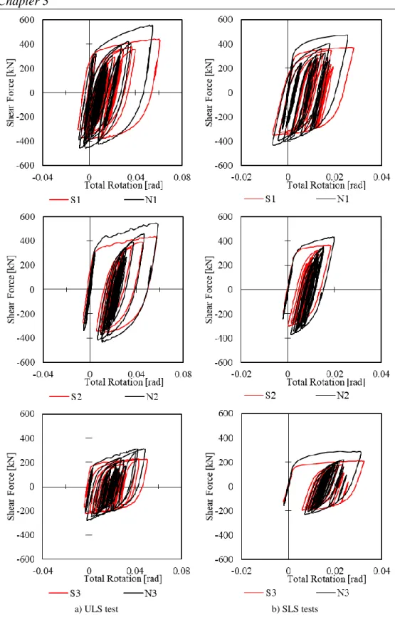
Figure 8 Shear force – link rotation for ULS and SLS tests (Ioan et al. 2016). ... 75
Figure 9 Link and slab deformations after each test set (Ioan et al. 2016) ... 76
Figure 10 Top displacement time history for south frame during second link removal process (Ioan et al. 2016) ... 77
Figure 11 Component idealization and tensile response curve ... 81
Figure 12 Computation of the bending resistance ... 81
Figure 13 Linear series assembling ... 82
Figure 14 Linear parallel assembling ... 83
Figure 15 Design moment-rotation of a joint ... 87
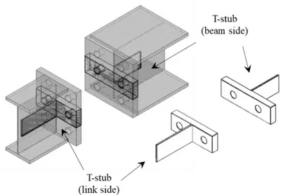
Figure 16 T-stub examples for the flush end-plate connection of detachable links ... 88
Figure 17 T-stub failure modes ... 89
Figure 18 Typical examples of effective lengths for bolt rows acting alone ... 90
Figure 19 Typical examples of effective lengths for bolt rows acting in combination ... 90
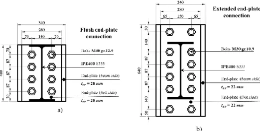
Figure 20 Connection layout: a) Flush end-plate connection, b) Extended end plate connection ... 92
Figure 21 Definition of values for the T-stub effective length evaluation ... 94
Figure 22 Analytical moment-rotation curve ... 96
Figure 23 Link assembly models with the two bolt typologies ... 97
16
Figure 25 Ductile Damage model ... 99
Figure 26 The nominal/net area for typical range of bolt diameters ... 100
Figure 27 HV vs. HR constitutive law model ... 101
Figure 28 Bolt interaction definition ... 102
Figure 29 Static scheme for the evaluation of the frame stiffness ... 103
Figure 30 DUAREM links and connections to beam ... 105
Figure 31 Cyclic loading protocol for DUAREM south frame links (Ioan et al., 2016) ... 106
Figure 32 Experimental vs Numerical Shear Force-Rotation Curves ... 107
Figure 33 Experimental vs Numerical ShearForce-Rotation Curves ... 107
Figure 34 Comparison of the cumulative plastic damage in the links of the tested structure and the PEEQ for the numerical models ... 108
Figure 35 Hot-rolled profiles investigated ... 111
Figure 36 Deformable restraints (DR) boundary conditions definition ... 111
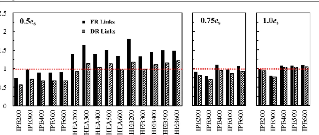
Figure 37 Shear overstrength for fully restrained (FR) links ... 113
Figure 38 Shear overstrength ... 114
Figure 39 Dependency between the shear overstrength and geometrical parameters (FR) ... 116
Figure 40 Axial force in the link ... 118
Figure 41 Normalized axial force curves for HE A links ... 118
Figure 42 M-N Interaction curve for the link EEP connection ... 122
Figure 43. Design ratios for FEP assemblies ... 125
Figure 44 Distribution of forces in the bolt rowsfor FEP connection IPE400 0.75es ... 126
Figure 45 M-N interaction curve for IPE400 0.75es ... 127
Figure 46 Deviation of design forces from the resistance curve ... 127
Figure 47 The deviation from the M-N interaction curve considering the axial force obtained using FR and DR boundary conditions ... 129
Figure 48. Design ratios for EEP assemblies according to Method 1 and Method 2 ... 130
Figure 49. Deviation of design forces from M-N curves of EEP assemblies ... 130
Figure 50 The boundary conditions (BC) for all analyzed models ... 132
Figure 51 Rotation evaluation measurements ... 134
Figure 52 Assembly typology ... 135
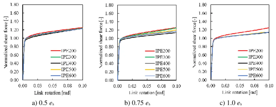
Figure 53 Normalized shear force curves for IPE link assemblies with FR boundary conditions... 136
Figure 54 Normalized shear force curves for IPE link assemblies with DR boundary conditions ... 137
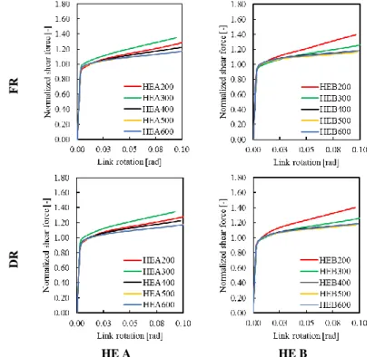
Figure 55 Normalized shear force curves for 0.5es HE A and HE B link assemblies ... 137
Figure 56. Shear response considering different boundary conditions ... 137
Figure 57 Shear overstrength at 8% link rotation vs. link depth/length ratio for the 0.5es links ... 138
Figure 58. Shear response for 400 mm, IPE assemblies considering the variation of mj ... 139
Figure 59. Shear response 400 mm HE assemblies considering the variation of mj ... 140
Figure 60 PEEQ in the link assembly IPE400 0.75es FR ... 141
17
Figure 62 Connection rotation contribution at 0.08rad link rotation ... 142
Figure 63 Influence of FR and DR boundary conditions for IPE400 0.75es ... 143
Figure 64 Variation of axial force in the link with the boundary conditions ... 144
Figure 65 Normalized axial force curves for IPE link assemblies with FR boundary conditions ... 145
Figure 66 Normalized axial force curves for IPE link assemblies with DR boundary conditions... 145
Figure 67 Normalized axial force curves for 0.5es HE A and HE B link assemblies ... 145
Figure 68 The normal stress for IPE400 0.75es... 146
Figure 69 Normalized axial force curves for 0.5es links comparison of FR vs DR boundary conditions ... 148
Figure 70 Normalized axial force curves for 0.5es links comparison of FR vs DR boundary conditions ... 149
Figure 71 Maximum compression force for the investigated link assemblies ... 149
Figure 72 Difference between the maximum compression force for models with FR and DR ... 150
Figure 73 Influence of section compactness ... 151
Figure 74 Connection/Link ratios for IPE and HEA 0.50es assemblies ... 152
Figure 75 Influence of depth and length ... 153
Figure 76 Connection/Link ratios for IPE assemblies ... 154
Figure 77 Influence of joint properties variation on link forces (example for IPE200 0.75es) ... 155
Figure 78 Connection/Link strength ratios for all FEP assemblies ... 156
Figure 79 Normalized axial force curves for IPE link assemblies with DR boundary conditions... 157
Figure 80 Normalized axial force curves for0.5es HEA link assemblies with DR boundary conditions ... 157
Figure 81 Normalized axial force curves for 0.5es HE B link assemblies with DR boundary conditions ... 157
Figure 82. Axial force for 400 mm, IPE assemblies considering the variation of mj ... 158
Figure 83. Axial force for 400 mm HE assemblies considering the variation of mj ... 159
Figure 84 The normal stress for IPE400 0.50es considering varying mj values ... 160
Figure 85 Comparison of the plots for varying boundary conditions (a) and varying section depth (b) ... 160
Figure 86 Comparison of the plots for varying link length (a) and varying section tyoe (b) ... 160
Figure 87 Normalized shear force curves for IPE link assemblies with FR boundary conditions... 162
Figure 88 Normalized shear force curves for IPE link assemblies with DR boundary conditions ... 162
Figure 89. Shear response considering different boundary conditions ... 163
Figure 90 Shear overstrength at 8% link rotation vs. depth-link length ratio for the IPE links ... 163
Figure 91 Normalized axial force curves for IPE link assemblies with FR boundary conditions ... 164
Figure 92 Normalized axial force curves for IPE link assemblies with DR boundary conditions... 164
Figure 93 Normalized axial force for IPE link assemblies ... 165
Figure 94 Results of analyses considering the variation of mj for IPE400 0.50es EEP assembly ... 165
18
Figure 96 Results of analyses considering the variation of mj for IPE400 1.00es EEP assembly ... 166
Figure 97 Comparative results of FEP and EEP assemblies considering the variation of mj ... 167
Figure 98 Connection rotation at 0.08rad link rotation ... 168
Figure 99 The normal stress for IPE400 0.75es considering varying mj values ... 169
Figure 100 Overlapped curves for varying length (a and b) and varying depth (c and d) ... 169
Figure 101 Shear overstrength vs. mj curves ... 171
Figure 102 Normalized axial force vs. mj curves ... 171
Figure 103 Shape of the function used to fit the v0.08 – mj data ... 172
Figure 104 Values of β for IPE profiles ... 173
Figure 105 Shape of the function used to fit the nfl,0.08 – mj data ... 174
Figure 106 Regressions for the nfl(mj) equation parameters a, k, b and c ... 175
Figure 107 Friction joint layout ... 185
Figure 108 The experimental set-up of preliminary investigations by Latour et al. (2014) ... 186
Figure 109 Meshed FE model ... 187
Figure 110 Plastic true-stress – true strain curves ... 188
Figure 111 Comparison of Implicit and Explicit analyses for same experimental test ... 189
Figure 112 Labelling for the analyses performed ... 190
Figure 113 Preloaded bolts distribution in assembly ... 191
Figure 114: sliding force vs displacement from implicit analysis ... 191
Figure 115: Sliding force vs displacement from explicit analysis. ... 192
Figure 116: bolt preload vs. displacement from explicit analysis. ... 193
Figure 117: Contact area vs. Pressure. ... 196
Figure 118: Contact Area Percentages of Slotted Inner Plate for Different Preload Torques. ... 196
Figure 119: Contact Pressures of Slotted Inner Plate for Different Preload Torques. ... 196
Figure 120: Friction coefficients generated from relation between experiment of 200 Nm and FE simulation μ(FN) vs μFpreμ(Fpre) ... 197
Figure 121: Friction coefficients generated from relation between experiment of 300 Nm and FE simulation μ(FN) μFN vs that calculated from experiment μ(Fpre) ... 197
Figure 122 Undesired response of friction materials ... 200
Figure 123 Different spray processes (Zimbru et al., 2018) ... 202
Figure 124 Lap shear specimen (Zimbru et al., 2018) ... 204
Figure 125 Hysteretic behavior of hard materials: a) M6 b) M8 c) M7 ... 205
Figure 126 Bolt forces and friction coefficient vs cumulative travel Zimbru et al (2018) ... 207
Figure 127 Hysteretic behavior of soft materials. a) M2, b) M3, c) M1, d) M4 ... 208
Figure 128 a) Actual friction coefficient- M4; b) Bolt forces – M4 ... 209
Figure 129. Geometry of Uniaxial FREEDAM sub-assembly with different number of disc springs 211 Figure 130 Lap shear joints with material M4: Sliding Force [kN] - Displacement [mm] ... 212
Figure 131 The friction coefficient curves for lap shear joints with material M4 ... 212
19
Figure 133 Lap shear joints with material M6: Sliding Force [kN] – Displacement [mm] ... 213
Figure 134: Geometric configurations of the two friction devices ... 217
Figure 135 Experimental setup ... 221
Figure 136 Geometrical details of the tested friction devices ... 222
Figure 137 Monitored parameters: global (a) and local response (b, c) ... 226
Figure 138 Layout of displacement transducers to measure the local response of joints ... 227
Figure 139 AISC 341-10 loading protocol up to 5% sorey drift ... 227
Figure 140 Comparison between the response of the 2 device configurations ... 228
Figure 141 T-stub opening versus damper rotation ... 229
Figure 142 L-stub opening versus damper rotation ... 230
Figure 143 Deformed shape of the tested specimens at chord rotation equal to 0.05 rad ... 231
Figure 144: Definition of the model labeling ... 232
Figure 145: The FE model for Assembly 1 ... 232
Figure 146: Updated models for Assembly 2 ... 233
Figure 147 Materials used for the preliminary FEAs ... 234
Figure 148 Experimental vs numerical results in terms of Bending Moment – Connection rotation .. 237
Figure 149 Experimental vs. numerical models after cyclic test up to 5%... 237
Figure 150 Normalised dissipated energy a) Friction energy and b) Plastic energy ... 238
Figure 151 Equivalent plastic damage (PEEQ) in the damper bolts ... 239
Figure 152 PEEQ Distribution at the end of the cyclic analysis for large joint assemblies... 239
Figure 153 Influence of the clamping force on the bending moment capacity ... 243
Figure 154 The influence of the friction coefficient on the bending moment resistance ... 244
Figure 155 Shear force transferred by different components ... 247
Figure 156 Shear force at the connection face ... 247
Figure 157 Distribution of shear in the connected elements at 0.04 rad damper rotation (Hogging) .. 248
Figure 158 Distribution of shear in the connected elements at 0.04 rad damper rotation (Sagging) ... 248
Figure 159 General mock-up test layout ... 250
Figure 160 Joint details of the 2 tested frames ... 251
Figure 161 The frame models ... 252
Figure 162 Material properties ... 253
Figure 163 Buckling modes for modelling imperfections ... 254
Figure 164 Imperfection effect on the bending capacity of the RBS ... 254
Figure 165 Loading actions ... 255
Figure 166 Schematic representation of SAP2000 models ... 256
Figure 167 Abaqus results of SPO Analysis and cyclic quasi static analysis for the RBS model ... 258
Figure 168 Bending moment in the RBS ... 258
Figure 169 Abaqus results of SPO Analysis and cyclic quasi static analysis for the FD model ... 259
Figure 170 Plastic deformation in the RBS frame (cyclic analysis) ... 260
20
Figure 172 Comparison of RBS and FD frame response ... 261
Figure 173 Comparison of RBS and FD joint response ... 262
Figure 174 Comparison between advanced and simplified RBS frame model ... 262
Figure 175 Comparison between advanced and simplified FD frame model ... 263
Figure 176 Ground motions accelerograms ... 264
Figure 177 Floor reactions and drift histories for the considered ground motions ... 265
Figure 178 PEEQ in the RBS on the 1st floor ... 265
Figure 179 Design algorithm ... 267
Figure 180 Details for the joint design force... 269
Figure 181 Points of reference for the design forces ... 269
Figure 182 Frame configuration ... 272
Figure 183 The tributary area for masses, additional gravity loads for P-Δ effects and the vertical loads directly assigned to the MRF ... 273
Figure 184 Design spectra ... 274
Figure 185 Menegotto-Pinto material model implemented in SeismoStruct ... 278
Figure 186 Node modelling ... 279
Figure 187 Spring calibration for FREEDAM Frames ... 280
Figure 188 The stiffness of the experimentally tested connections ... 281
Figure 189 Lateral force distribution ... 282
Figure 190 The base shear – top displacement curve ... 283
Figure 191 Comparison between natural signals and EC8 design spectrum ... 284
Figure 192 The designed MRF weight... 285
Figure 193 Normalized Pushover curves for MRF 6-3-6 ... 286
Figure 194 Average overdesign between modal and uniform lateral loading case ... 287
Figure 195 Average redundancy between modal and uniform lateral loading case ... 289
Figure 196 Average overall overstrength between modal and uniform lateral loading case ... 290
Figure 197 Transient interstorey drift for MRF 6-3-6 at DL (SF = 0.59) ... 292
Figure 198 Peak transient interstorey drift for MRF 6-3-6 at SD (SF = 1.00) ... 292
Figure 199 Transient interstorey drift for MRF 6-3-6 at CP (SF = 1.73) ... 294
Figure 200 Peak transient interstorey drift for MRF 6-3-6 ... 294
Figure 201 Catalogue developed by FIP Industriale ... 297
21
List of Tables
Table 1 Structural design assumptions ... 70
Table 2 Structural members details ... 71
Table 3 Summary of experimentally obtained values ... 74
Table 4 Strength evaluation for basic components according to EN 1993 1-8 ... 84
Table 5 Characteristics of experimental links ... 91
Table 6 Link connection components ... 92
Table 7 Effective length of the T-stub ... 93
Table 8 Formulas for the calculation of the three failure modes ... 94
Table 9 Formulas for the evaluation of the components ... 95
Table 10 Units for ABAQUS ... 98
Table 11 DUAREM experimental links geometry details (South Frame)... 104
Table 12 DUAREM links connection geometry details ... 104
Table 13 Evaluation of the frame flexural and axial stiffness ... 106
Table 14 Frame and connection stiffness for 0.50es set of links ... 112
Table 15 Polynomial regression coefficients ... 116
Table 16 Links normalized tensile forces at 0.08rad link rotation ... 119
Table 17 Tensile force at 0.08rad link rotation for links only and FR boundary conditions (nfl,T max) 119 Table 18 Summary of designed and analyzed connections ... 123
Table 19. Design force to resistance ratio according to Method 1 (FEP) ... 124
Table 20. Design force to resistance ratio according to Method 2 (FEP) ... 124
Table 21 Component information (force and lever arm) for the beam and link side for IPE400 0.75es ... 126
Table 22 M-N curve points for FEP connection IPE400 0.75es ... 127
Table 23 Design ratios for FEP connections ... 128
Table 24. Design force to resistance ratio according to Method 1 (EEP) ... 130
Table 25. Design force to resistance ratio according to Method 2 (EEP) ... 130
22
Table 27 Design forces and resistance in the links of the tested frame (Ioan et al 2016) ... 148 Table 28 Strength and stiffness ratios for the IPE200 0.75es ... 155 Table 29 The mj limit of the constant shear overstrength range ... 172 Table 30 Values for α ... 173 Table 31 Tensile force in the links considering the link profile and FR boundary conditions (nfl,T max)
... 174 Table 32 The set values of the parameters ... 190 Table 33 Given and obtained friction coefficients ... 194 Table 34 Given and obtained friction coefficients and slip rate data ... 194 Table 35 ID of specimens with disk springs ... 210 Table 36 Specimen geometrical configuration ... 223 Table 37 T-stub geometry details... 223 Table 38 L-stub geometry details... 224 Table 39 Friction pads geometry details ... 224 Table 40 Haunch geometry details ... 225 Table 41 Pretension levels in the bolts of the tested specimens ... 225 Table 42: Friction coefficients for material M-4 ... 235 Table 43 Bending moments for model FD 1-2-DS considering the variation of clamping force ... 243 Table 44 Bending moments for model FD 2-2-DS considering the variation of clamping force ... 243 Table 45 Bending moments for model FD 1-2 considering the friction coefficient variation ... 244 Table 46 Bending moments for model FD 2-2 considering the friction coefficient variation ... 244 Table 47 Ground motions details ... 263 Table 48 Summary of the FEAs results ... 264 Table 49 The combination coefficients ... 273 Table 50 Basic data of the selected ground motions ... 284 Table 51 Failure criteria for the EC8 limit states ... 291
24
List of Symbols and Abbreviations
Abbreviations:
AFC Asymmetric friction connection B31 a 2-node linear beam in space
BC Boundary conditions
BRB Buckling restrained braces
C3D8I 8-Node linear brick incompatible mode element C3D8R 8-Node linear brick reduced integration CBF Concentrically braced frames
CP Collapse prevention performance level D-EBF Dual eccentrically braced frame DL Damage limitation performance level DR Deformable restraints boundary conditions DS Disc spring washers
DOF Degree of freedom EBF Eccentrically braced frame EC8 Eurocode 8 compliant set of frames
EC8-MRF Moment resisting frame designed with traditional joints (Eurocode compliant)
EEP extended end-plate connection FD FREEDAM friction device
FD-A Set of frames designed according to the FD-A design procedure FD-B Set of frames designed according to the FD-A design procedure FD-MRF Moment resisting frames designed with friction dampers
FE Finite element
FEA finite element analysis FEM finite element model FEP Flush end-plate connection FO Fully operational test
FR Fully restrained boundary conditions FREEDAM Free from damage connections
GM Ground motion
IDA Incremental dynamic analysis HH high seismic hazard
25
HR British-French style preloadable bolts ‘High Resistance’
HV German style preloadable bolts ‘Hochfeste Bolzen mit Vorspannung’ MH Damage limitation limit state
MR Moment resisting
MRF moment resisting frame
NA Neutral axis
NC Near collapse limit state PEEQ equivalent plastic strain PGA peak ground acceleration
PO Pushover test
PRID Peak residual interstorey drift PTID Peak transient interstorey drift RBS reduced beam sections RC Reinforced concrete
RF Reaction force
RID Residual interstorey drift
SD Significant damage performance level
SF Scaling factor
SFC Symmetric friction connection SLS Serviceability limit state TID Transient interstorey drift U Displacement in Abaqus
UR Rotation in Abaqus
ULS Ultimate limit state VHH very high hazard
Symbols:
A Aria of cross section
Ab: Nominal area of the bolt shank Abe: Effective area of the threads Aeffective: Area of the threaded region Afl Flange area
Agross: Gross cross section of the shank As Bolt tensile area
Avz Web area of hot-rolled cross section according to EC3
Aw Web area
E Nominal modulus of elasticity of steel
F Force
Fc,fb,Rd Flange and web of beam or column in compression component FC,Rd Compression resultant of the joint
Fi Force of component i
Fp,C Recommended bolt preloading force according to EN1993 1-8 FRd Resistance of component
Fslip,eff Effective slip force Fslip,req Required slip force
Ft,Rd Resistance of a bolt in tension Ft,i,Rd Tensile resistance of component i
26
FT,Rd Resistance of T stub
FT,1,Rd Resistance of T stub at Failure Mode 1 FT,2,Rd Resistance of T stub at Failure Mode 2 FT,3,Rd Resistance of T stub at Failure Mode 3 Ft,i,Rd Resistance of component i in tension Ft,wb,Rd Beam web in tension component Fv,Rd Shear resistance of one bolt
Gk,i Characteristic value of the permanent load i
Hi,d Equivalent horizontal forces accounting for frame imperfections K Axial stiffness of joint component
Kaxial Axial stiffness of the EBF Kax,link Link axial stiffness Kfl,link Link flexural stiffness Kj,ax Joint axial stiffness
Krotational Rotational stiffness of the EBF
L Distance from the column axis to the point of application of the displacement histories
L1 Deformation of spring 1 (measurement of link distortion) L2 Deformation of spring 2 (measurement of link distortion)
Lb The bolt elongation taken equal to the grip length (total thickness of material
and washers), plus half the sum of the height of the bolt head and the height of the nut
Lb* Limit tifhtening length for the development of the prying forces Ls Shank length of the bolt
Ltg the length of the threaded portion included in the bolt's grip
M Bending moment
MRd Bending resistance
Mb,Rd is the design moment resistance of the beam cross-section, reduced if
necessary, to allow for shear
MCD Design bending moment for non-dissipative elements in moment resisting
frames equipped with friction connections
MCD* Initial value of design bending moment for non-dissipative elements MEd Design bending moment from the seismic combination
MEd,E Contribution of the exceptional loads to the design bending moment MEd,G Contribution of the gravitational loads to the design bending moment MFD Design bending moment for the friction damper (dissipative element for
moment resisting frames equipped with friction connections)
Mj Bending moment in joint Mj,Ed Joint design bending moment Mj,Rd: Design bending resistance of the joint
Mj,Sd Bending moment in the joint at a given moment Mpl,b,Rd Beam plastic bending resistance
Mpl,link Plastic bending moment of the link evaluated according to EC8 MRb Moment of resistance of the beams framing the node
MRc Moment of resistance of the columns framing the node
N Axial force
Nb Design pre-loading force in the bolts NEd Design axial force
NEd,E Design axial force – contribution of exceptional loads NEd,G Design axial force – contribution of gravitational loads
27
Nfl,link Plastic axial strength of the flanges (Npl,fl) Nj,Ed Joint design axial force
Nj,Rd Joint axial resistance Npl,Rd Plastic axial strength
Npl,fl Plastic axial strength of the flanges (Nfl,link)
Ptot Total gravity load at and above the storey considered in the seismic design
situation (for P-Δ effects)
R Position of the M-N curve
R* Deviation of the design pair from the M-N curve
Q Prying forces
Qk,i Characteristic value of the variable load i Sj Joint stiffness
Sj,ini Joint initial flexural stiffness
V Shear force
V1 Base shear at the occurrence of the first nonlinear event Vd Design base shear evaluated according to EC8 VEd Design shear force
VEd,E Design shear force – contribution of exceptional loads VEd Design shear force– contribution of gravitational loads Vj,Ed Joint design shear force
Vj,Rd Joint shear resistance
Vpl,link Plastic shear strength of the link evaluated based on the EC8 recommendations Vtot Total seismic storey shear (for P-Δ effects)
Vy Maximum base shear (occurrence of collapse)
Z Lever arm
a Length of the friction device (from tip to column face)
ag Gravitational acceleration b Width of the profile
bfl Width of profile flange bp Width of end-plate
beff,t,wb Effective width of the beam web in tension d Depth of cross section
d Bolt diameter
db Nominal diameter of the bolt
dt Design interstorey drift (for P-Δ effects)
e, ex Distance from the bolt to the plate edge (Design of bolted connections
according to EC3 1-8)
e Link length
elink Link lenght
emin Minimum between e and ex es Shear (short) link length limit
f Stiffness correlation factor assumed equal to 0.55
feffective Effective stress factual Actual stress fy Yield strength
fy,k Characteristic yield strength fy,fl Yield strength of the flange
fy,wb Yield strength of the web of the beam fub Ultimate bolt strength
28
h Depth of section
hi Lever arm of component i hr Lever arm of bolt row r hstorey Storey height
k5 Stiffness coefficient of end-plate in bending k10 Stiffness coefficient of bolts in tension ka Assembly stiffness
kb Bolt stiffness ke Elastic stiffness
keff,r Equivalent stiffness coefficient
keq Equivalent stiffness coefficient accounting for multiple bolt rows in tension ki Stiffness of component i
ki,r Stiffness of component i of bolt row r
kj,ax Ratio between axial stiffness of connection and link axial stiffness
(Kj,ax/Kax,link)
kj,fl Ratio between connection initial stiffness and link flexural stiffness
(Sj,ini/Kfl,link)
leff Effective length of the T-stub in tension
leff,cp Effective length considering circular patterns of the yield lines leff,ncp Effective length considering non-circular patterns of the yield lines mi Mass of floor i
mj Connection bending utilization factor (Mj,Ed/Mj,Rd)
m, mx Geometrical distance of connection defined in Figure 6.11 in EN1993 1-8. mx is the value of m for bolt rows outside the tension flange
m Utilization factor for beams of the FD-MRFs (
, , Ed pl b Rd
M M )
n Minimum between 1.25m and emin
nb Number of bolts
nc Number of bolts in compression
nfl Normalized axial force in link with respect to the axial capacity of the flanges nfl,T,max The axial force at 0.08rad link rotation, for the link alone assuming fully
restrained boundary conditions
nt Number of bolts in tension ns Number of friction surfaces p Vertical distance between bolt rows
pd Total design vertical loads for evaluation of frame imperfections
q Behavior factor
sh Distance from the tip of the haunch/rib plate to the column face tEP Thickness of end-plate
tf Thickness of T-stub flange tfl Thickness of flange tfb Thickness of beam flange tp Thickness of the plate tw Thickness of web twb Thickness of beam web ugap End-plate gap opening
v Normalized shear (with respect to Vpl,link)
v0.08 Shear overstrength of the link in a link-connection assembly, assuming fully
restrained boundary conditions, at 0.08rad link rotation
v0.08,FR Shear overstrength of the link considered alone, assuming fully restrained
29
vj Connection shear utilization factor (Mj,Ed/Mj,Rd)
w Horizontal distance between the bolts
z Connection lever arm
zeq Equivalent lever arm of bolt rows in tension Δ Deformation/Displacement
Δres,top Residual top drift
α Coefficient for the evaluation of effective length of the T-stub (EC3 1-8)
αh Reduction factor for the height h
αm Reduction factor for the number of columns in a row m γconnection Link connection rotation
γlink Link rotation γM0 Partial safety factor γmax Maximum link rotation
γov Coefficient accounting for the material yield strength variability γrez Maximum residual link rotation
δ Horizontal damper displacement
δadm Admissible interstorey drift δi Deformation of component i δr Design interstorey drift
δRd Ultimate deformation of component δres,storey Maximum residual interstorey drift
0 pl
Fracture plastic strain pl
n
Necking plastic strain
εeng Engineering strain εtrue True strain
θ Chord rotation
θ Interstorey drift sensitivity coefficient (for P-Δ effects)
θconnection Connection rotation evaluated based on the damper horizontal displacement ν Poisson coefficient
ν Reduction factor accounting for lower return period of earthquakes associated with DL requirements
µ Friction coefficient
μdyn 5% 5% fractile of the dynamic friction coefficient μdyn 95% 95% fractile of the dynamic friction coefficient μavg Average value of the dynamic friction coefficient
φ Rotation
ϕ Global initial frame deformation
ϕ0 Basic value for the initial frame deformation σeng Engineering stress
σtrue True stress
31
1 I
NTRODUCTION
The capacity-based design methodology applied for traditional steel structures like moment resisting frames or braced frames has been successful for many years now, yielding solutions capable to withstand severe earthquakes with diminishing casualties and economic losses. Proper design rules implemented at all levels (from global to the material) combined with advances in the design and analysis tools and the construction technologies available, led to structures with safe, predictable response under catastrophic events.
However, the last couple decades have seen severe earthquakes like the ones in Northridge (US, 1994), Kobe (Japan, 1995) or Christchurch (New Zealand, 2011) during which not only old, but also relatively new structures collapsed. Consequently, large research ventures took the direction of addressing the critical aspects related to the traditional systems (the SAC project - for the qualification of steel joints for moment frames in the US) while other research groups focused on proposing innovative solutions for seismic resistant structures. Many of the surfaced solutions, like the base isolation, the buckling restrained braces, viscous dampers and the friction connections (to name some), are being codified and implemented in practice in seismic areas around the world and have shown good performance in recent earthquakes (Bruneau & McRae, 2017).
32
Emerging innovative seismic devices enhance the seismic safety of buildings, represent sustainable alternatives by lowering the life-cycle costs and thus rendering steel structures more appealing compared with other materials. The new structural typologies also contribute to the number of code-compliant steel solutions, making the material more competitive.
The advantages are numerous for all the solutions which are already gaining popularity and most likely they will continue to be used, especially as they get tested in real-life in active seismic areas like New Zealand, Japan, California or central Italy. Nevertheless, some of the proposed devices are expensive and/or represent special patented devices, needing qualified workers and working by modifying the structural components or introducing significant changes in the design process.
Solutions that modify minimally the conventional structural systems (MRFs, EBFs, CBFs) are better understood and accepted by the environment of construction industry. The ideal solutions would therefore be based on existing structural configurations, would minimally modify the structure and its design and most importantly would render the building easily-repairable in the earthquake aftermath.
From the point of view of structural configuration suitability, there is no universally accepted superior solution – different types of structures adequate differently to different seismic zones. For example, braces naturally buckle at low forces and therefore, braced frames are not ideal for seismic areas with low intensity and frequent events and, moment resisting frames (MRFs) being more adequate owing to their high ductility. On the contrary, seismic areas where high intensity, seldom earthquakes occur, the higher stiffness of centrically braced frames (CBF) is an advantage. Eccentrically braced frames (EBFs) represent an intermediary solution, as function of the link length, different levels of ductility can be attained relative to the same stiffness.
33
The key aspect of MRFs (and of all steel structures actually) are the connections. The general practice is focused on designing and using either full strength, rigid or nominally pinned connections. In literature it has been proved that most connections are somewhere in between. Although accounting for this in the structural analysis might be more tedious, it is possible to design partial strength connections that have sufficient ductility and lead to lighter structural solutions (D’Aniello et al., 2017). However, significant plastic damage is expected in the connection and therefore the structural repair costs once the structure undergoes severe earthquake events, are high.
In the framework of steel structures, it is easy to obtain easily-repairable structures starting from any of the consecrated systems. The key for sustainable seismic design is low-damage, localized in easily replaceable elements of the structure. In the recent years many reliable solutions have surfaced, devices which render the structure easily repairable or with low damage. However not all solutions are equal and although many provide the desired results, costs, requirements for specialized workmanship, design complexity as well as comparative performance must be accounted for.
The use of innovative structural devices which effectively replace the traditional ones undoubtedly reduce the post-earthquake repair costs. Selecting one solution depends on various constraints like the ability of the designer to implement it (some devices are patented or require complex design techniques), the availability of specialized workers for installation, the physical and design related changes to the structure, the initial and life-cycle costs or the social confidence in the solution
Most of the innovative devices render the structures repairable in the earthquake aftermath. However, viscous and hysteretic dampers, as well as BRBs tend to be expensive, protected by patents, require special design methodologies and qualified workers in most of the cases. The most suitable
34
solutions are the friction connections for MRFs and CBFs and the replaceable links for EBFs.
As a comprehensive complete study of easily repairable steel structures for different seismicity areas, it was deemed necessary to focus on a braced system (EBF) and MRF. In the framework of these two structures, the most effective innovative solutions were investigated: replaceable links for EBFs and friction connections for MRFs.
Converting traditional EBFs to an easily repairable solution was proved to be feasible by simply introducing a connection that separates the link (the dissipative element) from the beam containing it (Stratan et al. 2004). In this case the re-centrability of the EBF can be enhanced by combining it with MR bays leading thus to a D-EBF (Ioan et al., 2016).
A friction connection is a type of partial strength connection designed in a way that disconnects the strength and stiffness of the moment resisting joint, changing the energy dissipation mechanism that eliminates most of the plastic deformation (being that localized in easily replaceable friction plates). The structure equipped with such connections could have significant inherent re-centrability because the framed members and the non-dissipative connections remain elastic and the residual drifts could be minimized by smartly replacing the friction devices.
The focus of this work is on these two types of connections that transform traditional structural systems with significant plastic damage concentrated in the members into structures that either have low damage (MRFs with friction devices) or into structures that have the damaged elements removable (EBFs with detachable links). Practically, the work will focus on traditional end-plate connections used in a special application and on innovative friction connection applied in typical MRFs.
35
*
1.1 M
OTIVATION
The main motivation for the current work is to contribute to the general effort of the research community towards rendering low-damage, cost effective and easily repairable structural solutions more readily available and closer to being codified.
Although the idea has been around for a while and replaceable links have been studied in the last years (Stratan et al., 2003 and 2004, Dubina et al., 2007 and 2008, Fussell et al., 2014, Ioan et al,. 2016, Ji et al., 2016b, Tan & Christopoulos, 2016), it’s not clear yet how the seismic links and the adjoining connections are to be designed. The research does not offer a definitive answer concerning the design forces (the shear overstrength, axial force) and there are no specific rules for the seismic design of the connection. In particular, the question needing an answer is whether the methodology available for the design of steel connections under static loads (EN1993 1-8) can be extended for the design of the seismic link’s connection and if not, how to adapt it.
In what regards the friction connections, due to their relative novelty much more aspects need to be addressed. To start, the principal parameters that can be assumed to influence the friction response are the friction coefficient of the sliding interfaces and the normal force applied (Marsh & Pall 1981, Butterworth & Clifton, 2000, Latour et al., 2011b). While the latter is an issue that is common in steel industry (issues related to applying the correct force and the losses of preload are often studied), the friction properties of surfaces to be selected for the proposed friction device need to be investigated in depth for a representative range of materials and the best solution should be selected. Subsequently, it can be guessed that due to the newly proposed joint geometries, there are effects that need to be investigated (contact area, shear
36
capacity, cyclic behavior etc.) and the best joint solution is to be selected for ulterior developments. A comprehensive study of the devices developed is needed in order to confirm the validity of the concept, looking at all key factors and the seismic performance of frames equipped with friction devices will complete the assessment of the proposed solution.
The aim of the current work is to give an answer to questions raised for the two solutions and offer therefore a basis for the future codification. A correct connection design in the case of these two systems (the link connection for the D-EBF and the friction connection for MRFs) is key in attaining the goal of structural solutions that are easily repairable in the aftermath of severe seismic events.
*
1.2 O
BJECTIVES
The main objective of the research is to perform an in-depth analysis of the two solutions and provide insight into the mechanism of the solutions and recommendations for the design. The set goals are achieved especially by using advanced finite element (FE) software to develop experimentally calibrated models able to accurately depict the steel connection response. Analytical methods for the design of connections and/or frames are discussed where it was the case. The work investigated both the local and global response (connections and structure – in the case of the friction devices).
A summary of the thesis, by chapters is hereinafter presented.
Chapter 1. Introduction
Chapter 2. State of the Art
Chapter 3. Bolted connections for detachable links
37
3.2 – DUAREM Research Project experimental campaign
This chapter briefly describes the DUAREM research project which focused on a full-scale test on a dual eccentrically braced frame equipped with detachable short links. The results of the experimental tests were used to calibrate the numerical models for the numerical study.
3.3 – European design of bolted moment-resisting connections
A general overview of the Component Method basic assumptions and methodology is described, as the main design procedure used in the European constructional steel practice. The chapter discusses the concepts of basic component, series and parallel component assembling, the T-stub, the connection moment-rotation characteristic and the design algorithm as implemented in the Eurocode.
3.4 – FE model assumptions and Validation
All the numerical modelling assumptions, general throughout the numerical analyses performed and presented in this first part of the thesis are summarized. The main aspects related to material modelling, boundary conditions and loading as well as meshing technique are discussed. The link-connection assemblies of the DUAREM mock-up frame were modelled in a manner simulating closely the real testing conditions, and the results were compared against the experimental results (in terms of shear-rotation response and deformed shape and plastic damage).
3.5 – Parametric study for the evaluation of the link connection design forces
This chapter presents the results of a large parametric study on short links (the models considering the link profile alone) in order to assess the actual design forces necessary for the design of the link end connections. Given that
38
the connection design forces are derived based on the links’ capacity, the actual values of the shear overstrength and the axial force must be evaluated.
3.6 –Design and verification of bolted connection for links
The link end connection is special due to its location and type of loading it has to withstand. Therefore, the design methodology implemented in EN1993 1-8 must be tweaked in order to fit this particular case. In order to take into account the potential development of catenary action, two verification methods were presented and the results were discussed by comparing them with the results of the design method.
3.7 – Assessment of the bolted link connections response
Finally, the last chapter presents the result of numerical analyses on link-connection assemblies, looking at the shear overstrength and axial force in the link and the effect the connection mechanical parameters (strength and stiffness) have on them. The chapter introduces proposals for the evaluation of design forces and design recommendations in the case of link-connection assemblies.
Chapter 4. Bolted friction connections for MRFs
4.1 – Basic concepts of friction
As an introduction to the study of friction devices, this chapter presents a brief description of general tribology notions,
4.2 –Definition of friction device properties
Prior to the study of full-scale devices, the investigation of the main sub-component was performed. The experimental and numerical campaigns were aimed at the study of a number of friction materials and the impact of several parameters (normal force, contact area, distribution of the normal force, speed of load application) on the sliding behavior of sub-components.
39
4.3 – The FREEDAM Device
The answers obtained from the investigations on the sub-components were subsequently used for the beam-to-column joints. This chapter presents the response of full-size beam-to-column assemblies equipped with friction connections. The chapter is divided in two main parts: the first dealing with the experimental tests and the second presenting the results of numerical investigations on the influence of certain parameters on the device response as well as the mechanism of shear force transfer.
4.4 – Full scale test on Frame equipped with the FREEDAM friction device
In this chapter are presented the results of preliminary FE analyses of full-scale structures tested considering traditional partial strength connections, reduced beam section, and friction connections. The analyses are performed using both simplified and advanced numerical approaches in order to assess the capacity of the software to model the structural response.
4.5 – Design and Analysis of Frames equipped with Friction Devices
In order to be used in practice, the structures equipped with friction connections require a ready-to-use design procedure. Two methodologies are proposed and assessed in this chapter by designing two sets of structures and comparing their performance in terms of static and dynamic nonlinear response.
Chapter 5. Conclusions
Each of the two main parts have summaries of the research and they are reiterated in this final chapter, together with the general conclusions concerning easily repairable seismic resistant steel structures
41
2 S
TATE OF THE
A
RT
Seismic resistant design
Structural design of buildings can be directed in three ways function of the destination and the architectural demands. The structures that are strategic for the society (nuclear power plants, hospitals, etc.) need to withstand earthquakes with high return periods remaining elastic. These structures fall within the first category of structural control i.e. hyper-resistant structures. The second category is comprised of active control systems which work by modifying the structural response at the occurrence of the seismic events. This kind of devices are effective however, the high cost is justified just in case of special structures (high-rise buildings, bridges etc.). The last category is the passive control systems which work by directing the seismic energy input into specific elements of the structure possessing enough capacity to dissipate it.
Given that the first two categories of seismic structural control are devoted to design of structures that represent a low percentage of the construction market and typically the design is not a strict code-compliant one, most of the efforts in improving and/or developing performant structural systems are focused on the third category.
The seismic base isolation systems studied in works like the ones by Kelly (1979), Aiken et al (1993) Christopoulos & Filiatrault (2000) Roy &
42
Chakraborty (2015) Cancellara & De Angelis (2017) are a special type of passive control systems that work as a barrier in between the soil and the superstructure, preventing the transfer of the seismic input and therefore limiting the demand on the structure. Although effectively used in practice, it constitutes a costly solution that has limitations.
The research conducted in the 20th century led to some, now consecrated, structural systems considering the largely favorite construction materials (reinforced concrete, masonr and steel). All the classical systems (being them frames or walls) assume that the seismic action is dissipated by plastic deformation of elements designed following the principles of the capacity design.
Capacity-based design
The capacity-based design principle is now at the base of all modern seismic design codes (EN 1998-1, ASCE 7-10, NZS 1170.5, BSLJ). The incorporation of the concept, as shown by Beatie et al. (2008) and Fardis (2018), followed several preliminary steps to seismic design regulations.
The first reference to the concept can be tracked back to the book by Blume, Newmark, and Corning, Design of Multistory Reinforced Concrete
Buildings for Earthquake Motions, published in 1961. Mete Sozen contributed
heavily to the work and the concept was included in the 1967 to 1968 revision of the Structural Engineers Association of California (SEAOC) recommendations. With the introduction of the new SEAOC rules in the 1968 New Zealand design code for public buildings, the term “capacity design” was born in the team surrounding Otto Glogau.
In New Zealand the concept was explained by Hollings (1969a and 1969b) for concrete structures (Figure 1) and as it gained attention and it was experimentally and theoretically developed, it was more comprehensively
43
explained in “Reinforced Concrete Structures” the book by Park and Paulay (1975). The principle was continually improved upon with ever extending applications. Works like the book by Paulay and Priestley (1992), containing detailing rules for reinforced concrete and masonry helped facilitate its implementation in practice.
a)
b)
Figure 1 Plastic mechanisms, Hollings 1969a
The principle proposes the design of certain elements (so called dissipative or ductile elements) of the structure for lower design forces,
44
rendering them purposely weaker (Hollings, 1968). The amount by which the forces are reduced for the design of these elements depends of the reserve of ductility available (structural typology, material). On the other hand, the non-ductile elements must be designed with an overstrength with respect to the dissipative element, in order to allow the formation of the desired global plastic mechanism.
Damage in past earthquakes
The extent of the post-earthquake losses throughout the last century in Japan (Y. Ishiyama, 2011), and looking at recent seismic events like the one in Christchurch, New Zealand (Clifton et al., 2011 and 2012, Kam and Pampanin, 2011) is sufficient proof to argue that there is always space for improvements in the seismic design and construction of structures.
The main causes for the extensive losses in terms of human lives and financial are not the same comparing the events at the beginning and the end of the past century. Moreover, tt stands to no doubt that the newer structures, designed according to modern regulations based on capacity design, have a better performance. During the events at the beginning of the century, the main culprit for the losses was the lack of knowledge with respect to seismic design, the poor constructional materials (timber, bricks) and the fires started by the earthquake and feeding onto the widely used timber structures (Kanto and San Francisco earthquakes). The events of the last decades surfaced problems of structural collapse related to detailing or poor implementation of the guidelines (Tremblay et al., 1995, Youssef et al., 1995, Nakashima et al., 1995, Watanabe et al., 1998). The basis for seismic design as well as the structural typologies are good, however, improvements are required at different levels (design rules, detailing rules, construction rules, etc.). Therefore, some of the collapse causes can be addressed without significantly altering the current design procedures.
45 Current design methodology
There is no doubt that the current practice is accustomed with the concept of capacity design but also to the specific types of structures that are by now consecrated systems i.e. MRFs, CBFs, EBFs, walls, etc., and when rationally applied the code guidelines lead to relatively economical solutions if only the initial cost is considered. The downside comes with the repair costs in the design-level earthquake aftermath. The ductile dissipative elements are usually structural members which undergo significant plastic damage, as intended, and must be replaced. In many cases this is no easy task, the repair costs being even larger than the complete replacement of the structure.
Traditional structural typologies
The simplest steel structures are composed of members connected in nodes which work together to transfer the vertical and horizontal forces. Several structural typologies can be identified for lateral resisting systems for seismic areas. The steel structural typologies are identified depending on the behavior of their primary resisting structure under seismic actions. In moment-resisting frames (MRF) members act primarily in flexure, concentrically-braced frames (CBF) have diagonal braces that act in tension and eccentrically-braced frame (EBF) transfer the forces by bending and/or shear deformation of links.
Each structural typology has its own structural features and applications, but the seismic design must adhere to two basic criteria: (1) sufficient stiffness to satisfy the serviceability limits and avoid damage to non-structural elements during events of low seismicity and (2) sufficient ductility to prevent collapse in the case of major seismic events.
MRFs and CBFs have been the default solutions for decades but they have widely opposite characteristics in terms of ductility and stiffness. It is not