Validation of RELAP5-3D
©
for liquid metal reactor
technologies
Facoltà di Ingegneria Civile e Industriale
Dipartimento di Ingegneria Astronautica, Elettrica ed Energetica
Corso di Dottorato di Ricerca in Energia e Ambiente – Scuola di Dottorato in Scienze e Tecnologie per l’Innovazione Industriale – XXXII Ciclo
Candidate
Vincenzo Narcisi Matricola 1394736
Thesis Advisor Co-Supervisor
Prof. Gianfranco Caruso Dott. Ing. Fabio Giannetti
Summary
LIST OF FIGURES ... vi LIST OF TABLES ... xi ABSTRACT ... xii 1 INTRODUCTION ...1 1.1 General background ...11.2 Why liquid metals? Advantages and drawbacks of liquid metals as coolants ...2
1.3 Verification and Validation ...4
1.4 Description of the code: RELAP5-3D© ...5
1.5 State of art and main challenges ...6
1.6 International and national framework of the research activity ...9
1.7 Structure of the document ... 10
2 COMPUTATIONAL ACTIVITY ON CIRCE POOL FACILTY ... 11
2.1 CIRCE-ICE computational activity ... 11
2.1.1 Description of the test facility ... 11
2.1.2 Overview of the experimental campaign ... 17
2.1.3 Description of the thermal-hydraulic model ... 18
2.1.4 Simulations results ... 26
2.1.4.1 Test A ... 27
2.1.4.2 Test I ... 33
2.1.5 Modelling analysis ... 45
2.1.5.1 Time step and mesh sensitivities ... 45
2.1.5.2 FPS radial conduction ... 46
2.1.5.3 Pool modelling ... 49
2.1.6 Conclusive remarks ... 52
2.2 CIRCE-HERO computational activity ... 53
2.2.1 Description of the test facility ... 54
2.2.2 Pre-test activity ... 57
2.2.2.1 Description of the thermal-hydraulic model ... 57
2.2.2.2 Identification of full power steady-state conditions ... 59
2.2.2.3 Transient analysis ... 63
2.2.2.4 Conclusive remarks ... 76
2.2.3 Post-test activity ... 76
2.2.3.1.1 Test 3 ... 76
2.2.3.1.2 Test 1 ... 77
2.2.3.2 Description of the thermal-hydraulic model ... 77
2.2.3.3 Simulations results ... 79
2.2.3.3.1 Test 3 ... 79
2.2.3.3.2 Test 1 ... 88
2.2.3.4 Conclusive remarks ... 97
3 COMPUTATIONAL ACTIVITY ON PHÉNIX DISSYMMETRIC TEST ... 100
3.1 Description of Phénix reactor ... 100
3.2 Overview of the dyssimmetric test ... 103
3.3 Description of the thermal-hydraulic model ... 103
3.4 Simulations results ... 107
3.5 Conclusive remarks ... 124
4 COMPUTATIONAL ACTIVITY ON PERSEO FACILITY ... 125
4.1 Description of the test facility ... 125
4.2 Overview of the experimental test ... 127
4.2.1 Test 7 Part 1 ... 127
4.2.2 Test 7 Part 2 ... 129
4.3 Description of the thermal-hydraulic model ... 130
4.4 Simulations results ... 134
4.4.1 Test 7 Part 1 ... 134
4.4.2 Test 7 Part 2 ... 146
4.5 Conclusive remarks ... 156
5 COMPUTATIONAL ACTIVITY ON ALFRED REACTOR ... 158
5.1 The ALFRED reference concept: LEADER project ... 158
5.1.1 Description of the ALFRED reference configuration... 158
5.1.2 Description of the thermal-hydraulic model ... 161
5.1.3 Application of the RELAP5-3D/PHISICS coupling methodology for the evaluation of the full power steady-state conditions within the reactor core ... 163
5.1.3.1 Neutronic kinetic and thermal-hydraulic model of ALFRED reactor ... 163
5.1.3.2 Full power steady-state calculation ... 164
5.1.4 Full power steady-state calculation ... 167
5.1.5 NK-TH calculations: transient analysis ... 170
5.1.5.2 UTOP transient ... 172
5.1.6 Conclusive remarks ... 173
5.2 A revised concept of ALFRED reactor ... 173
5.2.1 Overview of the improved concept ... 174
5.2.2 Description of the thermal-hydraulic model ... 179
5.2.3 Simulations results ... 184
5.2.4 Conclusive remarks ... 203
6 A METHOFOLOGY FOR THE UNCERTAINTY QUANTIFICATION BASED ON RELAP5-3D/RAVEN COUPLING . 205 6.1 Overview of the test facility and of the numerical model ... 205
6.2 Experimental campaign ... 207
6.3 Probabilistic comparison metrics ... 207
6.4 RELAP5-3D/RAVEN calculations ... 211
6.5 Conclusive remarks ... 219
7 CONCLUSIONS ... 221
7.1 Pool modelling ... 221
7.2 Liquid metal system operation ... 224
7.3 Passive safety system ... 225
7.4 BEPU methodology ... 226
NOMENCLATURE ... 227
Abbreviations and acronyms ... 227
Roman letters ... 230
Greek letters ... 230
LIST OF FIGURES
Figure 1. System development timelines: 2002 Roadmap (left) and 2013 Roadmap Update (right) ...2
Figure 2. CIRCE facility ... 13
Figure 3. CIRCE-ICE test section ... 14
Figure 4. Lower grid ... 15
Figure 5. Fuel Pin Simulator: axial division ... 15
Figure 6. Spacer grid ... 16
Figure 7. Disposition of the main components ... 16
Figure 8. HX bayonet tube ... 17
Figure 9. CIRCE-ICE nodalization scheme: model #1 ... 24
Figure 10. Pool modelling approach: model #1 ... 25
Figure 11. FPS nodalization scheme: model #2 ... 25
Figure 12. MULTID component: model #2 ... 26
Figure 13. Test A: boundary conditions ... 27
Figure 14. Test A: LBE mass flow rate ... 29
Figure 15. Test A: LBE FPS inlet/outlet temperature ... 29
Figure 16. Test A: LBE HX inlet/outlet temperature ... 30
Figure 17. Test A: HX power removed ... 30
Figure 18.Test A: pool thermal stratification... 32
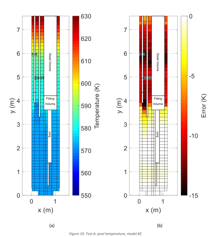
Figure 19. Test A: pool temperature, model #2 ... 33
Figure 20.Test I: boundary conditions ... 34
Figure 21. Test I: LBE mass flow rate ... 36
Figure 22. Test I: LBE FPS inlet/outlet temperature ... 37
Figure 23. Test I: LBE HX inlet/outlet temperature ... 37
Figure 24. Test I: HX power removed ... 38
Figure 25. Test I: LBE DHR inlet/outlet temperature ... 38
Figure 26. Test I: DHR power removed ... 39
Figure 27. Test I: pool thermal stratification (25000 s) ... 41
Figure 28. Test I: pool thermal stratification (28000 s) ... 42
Figure 29. Test I: pool thermal stratification (100000 s) ... 42
Figure 30. Test I: pool temperature, model #2 ... 43
Figure 31. Test I: error distribution map, model #2 ... 44
Figure 32. Time step sensitivity ... 45
Figure 33. Mesh sensitivity ... 46
Figure 34. FPS outlet temperature: radial conduction effect (20000 s). ... 47
Figure 35. FPS outlet temperature: comparison with experimental measurements (20000 s) ... 48
Figure 36. FPS outlet temperature: radial conduction effect (89000 s) ... 48
Figure 37. FPS temperature: comparison with experimental measurements (89000 s) ... 49
Figure 38. Pool modelling: single pipe ... 50
Figure 39. Pool modelling: three parallel pipes with cross junctions ... 51
Figure 40. Influence of the momentum equations ... 51
Figure 41. HERO test section ... 55
Figure 42. DWBT SG bundle... 56
Figure 44. CIRCE-HERO nodalization scheme: 1D region ... 58
Figure 45. Full power calculations: boundary conditions ... 60
Figure 46. Case 1: LBE mass flow rate ... 61
Figure 47. Case 1: LBE temperatures ... 61
Figure 48. Case 1: FPS temperatures ... 62
Figure 49. Case 1: pool temperatures ... 62
Figure 50. LBE free levels ... 63
Figure 51. Transient test: boundary conditions ... 64
Figure 52. Transient test: decay heat curve ... 65
Figure 53. TrT 1: LBE mass flow rate ... 66
Figure 54. TrT 1: LBE temperatures ... 67
Figure 55. pool temperature evolution ... 68
Figure 56. TrT 1: thermal stratification ... 69
Figure 57. TrT1: FPS temperature evolution ... 70
Figure 58. First comparison: LBE mass flow rate ... 71
Figure 59.First comparison: FPS temperatures ... 71
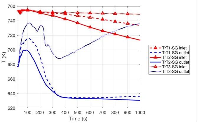
Figure 60. First comparison: SG temperatures ... 72
Figure 61. First comparison: thermal stratification ... 72
Figure 62. First comparison: pool temperature ... 73
Figure 63. Second comparison: LBE temperatures ... 74
Figure 64. Third comparison: LBE temperatures ... 75
Figure 65. Second and third comparisons: thermal stratification ... 75
Figure 66. Post-test simulations: thermal-hydraulic model of 1D region ... 79
Figure 67. Test 3 – Pool thermal stratification: full power steady-state conditions ... 81
Figure 68. Test 3 – Pool temperature ... 82
Figure 69. Test 3 – LBE mass flow rate ... 84
Figure 70. Test 3 – FPS inlet and outlet temperature ... 85
Figure 71. Test 3 – LBE temperature through the SG ... 85
Figure 72. Test 3 – Power removed by the SG ... 86
Figure 73. Test 3 – Pool thermal stratification: final conditions ... 86
Figure 74. Test 3 – FW mass flow rate through DWBTs 0 and 4 ... 87
Figure 75. Test 3 – Steam temperature ... 88
Figure 76. Test 1 – LBE mass flow rate ... 90
Figure 77. Test 1 – FPS inlet and outlet temperature ... 91
Figure 78. Test 1 – Temperature profile at the outlet of the FPS active region ... 92
Figure 79. Test 1 – FPS outlet temperature: R5-3D calculation ... 93
Figure 80. Test 1 – LBE temperature through the SG ... 94
Figure 81. Test 1 – Steam outlet temperature ... 94
Figure 82. Test 1 – Pool thermal stratification: initial conditions ... 95
Figure 83. Test 1 – Pool thermal stratification: final conditions ... 96
Figure 84. Test 1 – Pool thermal stratification: R5-3D results ... 97
Figure 85. Scheme of the Phénix reactor block [69] ... 101
Figure 86. Top view of the core [71] ... 102
Figure 87. Top view of the reactor [69] ... 102
Figure 89. Scheme of MULTID component ... 106
Figure 90. Comparison of Phénix relevant heights... 106
Figure 91. Overview of the nodalization scheme of PPs, IHXs and VCS ... 107
Figure 92. Steady-state conditions ... 109
Figure 93. Power removed by IHXs ... 110
Figure 94. Power removed by L1 and L3 (%) ... 111
Figure 95. IHX-1B outlet temperature ... 111
Figure 96. Relevant slice ... 112
Figure 97. Primary system temperature: initial conditions ... 114
Figure 98. Primary system temperature: 30 s ... 115
Figure 99. Primary system temperature: 60 s ... 116
Figure 100. Primary system temperature: 90 s ... 117
Figure 101. Primary system temperature: 120 s ... 118
Figure 102. PP1 inlet temperature ... 119
Figure 103. PP2 inlet temperature ... 119
Figure 104. PP3 inlet temperature ... 120
Figure 105. Core outlet temperature ... 120
Figure 106. IHX-1A inlet temperature ... 121
Figure 107. IHX-3B inlet temperature ... 121
Figure 108. IHX-3A inlet temperature ... 122
Figure 109. Temperature distribution: 60 s... 122
Figure 110. Temperature distribution: 160 s... 123
Figure 111. Temperature distribution: final condition ... 123
Figure 112. PERSEO facility: scheme [81] ... 127
Figure 113. PERSEO: nodalization scheme ... 133
Figure 114. Test 7 Part 1: steam flow rate ... 137
Figure 115. Test 7 Part 1: condensate flow rate ... 137
Figure 116. Test 7 Part 1: HX power ... 138
Figure 117. Test 7 Part 1: primary pressure ... 138
Figure 118. Test 7 Part 1: steam temperature ... 139
Figure 119. Test 7 Part 1: condensate temperature ... 139
Figure 120. Test 7 Part 1: HXP level ... 140
Figure 121. Test 7 Part 1: OP level ... 140
Figure 122. Test 7 Part 1: HXP temperature T-Q037 ... 141
Figure 123. Test 7 Part 1: HXP temperature T-Q034 ... 141
Figure 124. Test 7 Part 1: HXP temperature T-Q031 ... 142
Figure 125. Test 7 Part 1: HXP relative pressure ... 142
Figure 126. Test 7 Part 1: OP temperature T-P008 ... 143
Figure 127. Test 7 Part 1: OP temperature T-P021 ... 143
Figure 128. Test 7 Part 1: HX pressure drop ... 144
Figure 129. Test 7 Part 1: Injector pressure drop ... 144
Figure 130. Test 7 Part 1: HX upper header outer wall temperature ... 145
Figure 131. Test 7 Part 1: HX lower header outer wall temperature ... 145
Figure 132. Test 7 Part2: steam flow rate ... 147
Figure 134. Test 7 Part2: HX power ... 148
Figure 135. Test 7 Part2: primary pressure ... 149
Figure 136. Test 7 Part2: steam temperature ... 149
Figure 137. Test 7 Part2: condensate temperature ... 150
Figure 138. Test 7 Part2: HXP level ... 150
Figure 139. Test 7 Part2: OP level... 151
Figure 140. Test 7 Part2: HXP temperature T-Q037 ... 151
Figure 141. Test 7 Part2: HXP temperature T-Q034 ... 152
Figure 142. Test 7 Part2: HXP temperature T-Q031 ... 152
Figure 143. Test 7 Part2: relative pressure HXP ... 153
Figure 144. Test 7 Part2: OP temperature T-P008 ... 153
Figure 145. Test 7 Part2: OP temperature T-P021 ... 154
Figure 146. Test 7 Part2: HX differential pressure ... 154
Figure 147. Test 7 Part2: injector differential pressure ... 155
Figure 148. Test 7 Part2: HX upper header outer wall temperature ... 155
Figure 149. Test 7 Part2: HX lower header outer wall temperature ... 156
Figure 150. ALFRED reactor block: vertical (a) and horizontal (b) views ... 159
Figure 151. ALFRED core configuration [86] ... 160
Figure 152. FA geometry [86] ... 161
Figure 153. ALFRED primary system: nodalization scheme ... 162
Figure 154. Simplified thermal-hydraulic model ... 163
Figure 155. ALFRED core NK nodalization: material axial distribution for each assembly type ... 164
Figure 156. Fission power ... 165
Figure 157. Pb outlet temperature ... 165
Figure 158. Centerline fuel temperature... 166
Figure 159. Relative error on mass flow ... 166
Figure 160.Neutron flux... 167
Figure 161. Mass flow rate distribution ... 168
Figure 162. Active core: Pb outlet temperature ... 169
Figure 163. Primary system: Pb temperature ... 170
Figure 164. ULOF transient: main results ... 171
Figure 165. UTOP transient: main results... 172
Figure 166. internal view of the ALFRED revised configuration [87]... 175
Figure 167. Core map of the revised ALFRED core [25] ... 176
Figure 168. Layout of the DHR system [79] ... 178
Figure 169. Nodalization scheme: ALFRED revised concept ... 182
Figure 170. MULTID components: configuration ... 183
Figure 171. Subchannel modelling of the hottest FA ... 183
Figure 172. Full power steady-state condition within RV ... 186
Figure 173. DHR system operation: initial conditions ... 188
Figure 174. Pressure within the secondary systems: zoom on the firsts 250 s ... 189
Figure 175. Power removed by the SGs: zoom of the firsts 250 s... 189
Figure 176. DHR system operation: 200 s ... 190
Figure 177. Steam flow rate across the secondary system 1 ... 190
Figure 179. DHR system operation: 1 h ... 191
Figure 180. DHR system operation: 13 h ... 192
Figure 181. DHR system operation: 46 h ... 192
Figure 182. Power removed by the SGs ... 194
Figure 183. Power removed by the SGs: zoom on y-axis ... 194
Figure 184. Primary mass flow rate: zoom of the firsts 5400 s ... 195
Figure 185. Primary mass flow rate ... 195
Figure 186. Pb temperature drop across the SG: zoom of the firsts 5400 s ... 196
Figure 187. Pb temperature drop across the SG ... 196
Figure 188. Water temperature through the bayonet elements ... 197
Figure 189. Pb temperature increase across the core ... 198
Figure 190. Core outlet temperatures: zoom of the firsts 250 s ... 198
Figure 191. Core outlet temperatures ... 199
Figure 192. Asymmetric effects: zoom of the first hour ... 200
Figure 193. Asymmetric effects ... 200
Figure 194. Temperature evolution within the RV ... 202
Figure 195. Pb temperature at the outlet of the hottest FA ... 203
Figure 196. NACIE primary system: schematic layout (a) and nodalization scheme (b) ... 206
Figure 197. Schematic view of the FPS (a) and of the heat exchanger (b) ... 206
Figure 198. CDF area metric example ... 208
Figure 199. PDF area metric example... 209
Figure 200. PDF difference metric example ... 210
Figure 201. Integral function (CDF) of PDF difference metric example ... 211
Figure 202. Test 201: main results ... 213
Figure 203. Test 203: main results ... 214
Figure 204. Test 201 (12000 s): LBE mass flow rate ... 216
Figure 205. Test 201 (12000 s): FPS inlet temperature ... 216
Figure 206. Test 203 (18000 s): LBE mass flow rate ... 217
Figure 207. Difference PDF metric: Test 201 LBE mass flow rate (12000 s) ... 218
Figure 208. Difference PDF metric: Test 201 FPS inlet temperature (12000 s)... 219
LIST OF TABLES
Table 1. Coolant comparison ...4
Table 2. Experimental tests: time events ... 18
Table 3. Models #1 and #2: main parameters ... 26
Table 4. CIRCE-HERO modelling dimensions ... 57
Table 5. Full power calculations: boundary conditions ... 59
Table 6. Full power calculations: main results ... 63
Table 7. TrT 1: main events ... 66
Table 8. Post-test simulations: model dimensions ... 79
Table 9. Test 3 – Full power calculations: main results ... 81
Table 10. Test 1 – Full power calculation: main results ... 89
Table 11. Dissymmetrical test: main events sequence ... 103
Table 12. Nominal boundary conditions ... 107
Table 13. Steady-state calculation ... 108
Table 14. Test 7 Part 1: phenomenological windows ... 128
Table 15. Test 7 Part 1: triggering valve events timing [81] ... 129
Table 16. Test 7 Part 2: phenomenological windows ... 130
Table 17. Test 7 Part 2: triggering valves events timing [81] ... 130
Table 18. PERSEO model: main parameters ... 132
Table 19. PERSEO facility: measurement errors [83] ... 134
Table 20. ALFRED full power calculation: boundary conditions ... 167
Table 21. ALFRED main parameters in the stages of operation [97]... 173
Table 22. ALFRED modelling: main parameters ... 184
Table 23. Boundary conditions: power distribution ... 184
Table 24. Full power calculation: steady-state results ... 185
Table 25. Power during decay heat ... 187
Table 26. Maximum temperature conditions and corresponding holding time in accident scenario (stage 2) . 199 Table 27. NACIE test matrix ... 207
Table 28. Selected uncertainty parameters (3σ) ... 212
Table 29. Probabilistic analysis: main results ... 215
Table 30. CDF area difference ... 218
ABSTRACT
The present research work set in an international and national context that includes the efforts of several universities and research centers in a strict collaboration. Within the international framework, the Department of Astronautical, Electrical and Energy Engineering (DIAEE) of “Sapienza” University of Rome (UNIROMA1) has been recently involved in the Horizon 2020 (H2020) SESAME (thermal-hydraulic Simulations and Experiments for the Safety Assessment of MEtal-cooled reactors) project. The project aims to contribute to the liquid metal-cooled fast reactors (LMFRs) development, including the advanced numerical approaches for the design and safety evaluation of the technologies. Regarding the national context, R&D efforts are mainly dedicated on the development of the lead-cooled fast reactor (LFR) technologies, involving three main partners: ENEA (Italian National Agency for New Technologies, Energy and Sustainable Economic Development), CIRTEN (Interuniversity Consortium for Technological Nuclear Research) and the industrial partner ANSALDO NUCLEARE. Strong collaboration and comparing among the three partners are devoted to the development of the reference LFR project: the Advanced Lead Fast Reactor European Demonstrator (ALFRED).
In this framework, the purpose of the present research activity has been to contribute to the understanding of relevant thermal-hydraulic phenomena that characterize the operations of the LMFR, and to the fundamental validation process of the innovative numerical tools, adopted for safety analysis and licensing of new Generation IV (GEN IV) technologies. The research activity has dealt with the validation of RELAP5-3D© (R5-3D) for applications on liquid metal-cooled pool-type fast reactors.
The thesis is divided in seven chapters. The first one is dedicated to the definition of the general background of the research activity. Chapters 2, 3 and 4 are focused on the validation of R5-3D for application on LMFRs. The merits of the simulations are evaluated comparing the results with experimental data from CIRCE (CIRColazione Eutettico) facility, Phénix reactor and PERSEO (in-Pool Energy Removal System for Emergency Operation) facility. The numerical activities have been used to explore and validate different modelling approaches and the acquired know-how has been used to support the design of ALFRED reactor. This topic is examined in chapter 5 that is basically divided in two subsections: the first one analyzes the reference configuration of ALFRED and the second one deals with the revised configuration of the reactor. Chapter 6 presents a methodology for the uncertainty quantification, based on the coupling approach between RELAP5-3D and RAVEN codes. Experimental data from the loop-type facility, called NACIE (NAtural CIrculation Experiment), have been used for the qualification of the methodology. Finally, the main results and guidelines, as well as the weaknesses and the future perspective coming out during the present research activity, are pointed out in chapter 7.
CIRCE is a multipurpose pool-type facility aimed to investigate thermal-hydraulics of innovative heavy liquid metal (HLM) cooled pool-type systems. Two experimental campaigns have been considered in the present work, related to two different configurations of the facility: ICE (Integral Circulation Experiment) and HERO (Heavy liquid mEtal pRessurized water cOoled tubes).
The experimental campaign promoted in CIRCE-ICE test facility was aimed to investigate the thermal-hydraulics of a complex HLM system and to provide data for validation of computational tools. Two experimental tests have been analyzed in this activity: Test A, consisting in a transition from no-power to full power steady-state conditions, and Test I, consisting in a transition from gas-enhanced circulation (GEC) to natural circulation (NC), simulating a protected loss of heat sink plus loss of flow accident. The computational activity has been addressed to investigate the capability of RELAP5-3D© to predict thermal stratification phenomenon in an HLM pool. Several examples were found in literature concerning the simulation of large tanks with RELAP5. The state of art on the simulation of the thermal stratification in large pool has been confirmed by the calculations performed
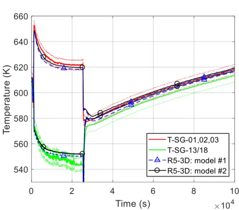
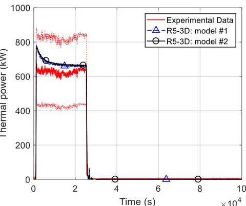
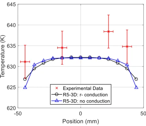
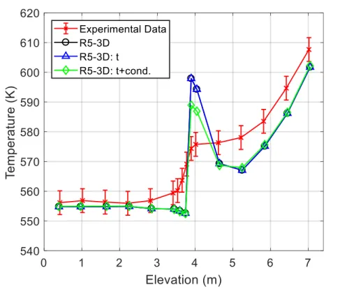
on CIRCE-ICE. The mono-dimensional approach, using a single channel for pool modelling, highlights discrepancies with the experimental data, failing on the prediction of the axial temperature profile. A high peak temperature in the middle of the tank, which is not observed by the experiment, is caused by a total absence of the natural flow within the pool. In order to verify how the axial conduction within the fluid can improve the computational results, a thermal conduction model has been implemented in the nodalization, using several heat structures that couple adjacent meshes. As expected, the axial conduction reduces the peak but not enough to match the experimental temperature profile. To reproduce buoyancy within the LM tank, the pool has been divided in three vertical channels, connected with cross junctions. This approach (model #1) has shown good capabilities on the thermal stratification evaluation. The qualitative trend is well reproduced, predicting two relevant stratifications in the upper and in the middle volumes of the pool. In the lower part of the tank, the LBE temperature is very well simulated but, at 4 m, the plateau temperature is under-predicted of about 15 K and this discrepancy is maintained up to the cover gas. R5-3D was improved with a fully integrated multi-dimensional (MULTID) modelling scheme, mainly developed for volumes where the movement of the fluid is preferably 1D. The MULTID component has been used for the simulation of CIRCE pool. In addition, the fuel pin simulator (FPS) modelling has been improved for the subchannel analysis (model #2). Several figures of merit have been selected, assessing the capabilities of the two models to reproduce thermal-hydraulics of an HLM cooled pool-type system in safety-relevant operations. The comparison with experimental data has highlighted excellent capabilities of the two models to predict thermal-hydraulics of the main flow path, managing to evaluate the most important features: LBE mass flow rate in both GEC and NC conditions, heat exchange within FPS, heat exchanger (HX) and decay heat removal system (DHR), and heat losses. In addition, model #2 assesses RELAP5-3D abilities as a subchannel analysis code, in both GEC and NC operations. The effect of the radial conduction has been evaluated: specific heat structures have been implemented to reproduce thermal conduction through adjacent subchannels. This analysis has shown small effects of the radial conduction, even if, in low flow rate regimes, such as NC operation, it provides not negligible improvement on the prediction of the temperature profile. In this case, the simulation is in good agreement with experimental data; the highest discrepancies are observed in the edge of the bundle (4 degrees) where the errors can be justified by the uncertainties related to the thermocouples positions. Focusing on the pool simulation, the MULTID component has introduced relevant improvements on the prediction of the thermal stratification phenomenon. The two relevant stratifications have been observed by the calculation. The temperature in the lower part matches very well the experimental measurements. The lower stratification level is well predicted and the temperature hot plateau underestimation has been reduced to 5 K. After the transition from GEC to NC, both the models are able to predict the upper stratification attenuation and the movement of the lower one below the DHR outlet. In the long term, the two calculations provide the same temperature profile that matches well the experimental trend, limiting the discrepancies below 4 degrees. Evaluation of the axial conduction within the pool has been performed, highlighting limited effects, especially when the natural circulation (NC) inside the pool is considered.
HERO test section was employed in CIRCE facility to investigate thermal-hydraulics of a double wall bayonet tube (DWBT) steam generator (SG), in a relevant configuration for ALFRED SG. Moreover, a validation benchmark was proposed within the H2020 SESAME project to asses the capabilities of different computational tools to predict the main thermal-hydraulic phenomena in an HLM-cooled pool-type facility. UNIROMA1 supported the definition and the realization of the experimental campaign, developing a nodalization scheme, based on the validated CIRCE-ICE model, for the pre-test analysis. The calculations have investigated different transient scenarios, highlighting the capabilities of HERO test section to guarantee sufficient NC to remove the decay heat in the short term. Based on these results, a set of three experimental tests has been performed, consisting in three protected loss of flow accidents (PLOFAs), occurred during the normal operation of the facility. The numerical activity has concerned two of the three tests, adopting an improved nodalization scheme. Regarding post-test
analysis of Test 3, simulation of the full power conditions is globally in agreement with experimental data for all the primary circuit physical quantities monitored, including the thermal stratification phenomenon; some discrepancies are highlighted on the secondary side, mainly due to the lack of some information which determines large uncertainties on the boundary conditions related to the operation of the secondary loop. Starting from the full power steady-state conditions, two transient calculations have been performed, assuming the same boundary conditions, except for the feedwater (FW) mass flow rate after the transition event. Case 1 assumes the reference value of the secondary flow rate (0.078 kg/s), obtained with the energy balance equation applied to the FW pre-heater. This calculation highlights an overestimation of the power removed by the SG. A second calculation has been performed adjusting the total secondary flow rate to 0.047 kg/s; that value guarantees the correct SG power. Both the simulations are in good agreement with experimental data in the first 200 s, reproducing very well the first minutes after the transition event. After the Ar injection cut off, the first calculation provides a good estimation of the minimum value of the LBE MFR, underpredicted by the second calculation of about 2 kg/s. The long term behavior strongly depends on the feedwater mass flow rate. Case 1 shows an overestimation of the whole system energy unbalance, leading to the overprediction of the natural circulation contribution and of the cooling trend. The SG power balance analysis has highlighted an overestimation of the power removed of about 30% of the experimental value. The large uncertainties related to the measurement of the secondary system quantities have suggested the calibration of the secondary flow rate to obtain the correct SG power removed. This assumption has been justified comparing the experimental flow rate, acquired at the inlet of the tubes 0 and 4, with the simulation results: the experimental data are underestimated but the calculation results remain within the experimental uncertainty bands. Looking at the primary system, the assumption of a lower FW flow rate leads to a better agreement with experimental data, providing a good estimation of the long term behavior. Some discrepancies are still maintained on the secondary side, where the steam outlet temperature is overpredicted by the code. The differences could be due to a not perfect agreement of the powder thermal conductivity, which represents a large source of uncertainties. This opens the possibility to continue the post-test analysis for the secondary side, leading an improved experimental results analysis, despite the good global results obtained. Similar conclusions are obtained from the post-test analysis of Test 1, confirming good capabilities of R5-3D to reproduce thermal-hydraulics of HLM-cooled systems in safety-relevant operations. In addition, the subchannel analysis performed has highlighted a good prediction of the subchannel thermal-hydraulics within the FPS bundle in the postulated transient accident.
The Phénix Dissymmetric End-of-Life test, proposed for a benchmark exercise within the H2020 SESAME project, offered useful data for the analysis of more complex systems where asymmetrical effects could play a relevant role in the system thermal-hydraulics. As a participant to the validation benchmark, in collaboration with ENEA, UNIROMA1 has developed a detailed nodalization of the reactor, including a three-dimensional modelling of the pools and an assembly per assembly core modelling in the active region, suitable for a neutron kinetic and thermal-hydraulic (NK-TH) coupling calculation. The full power calculation has highlighted a good capability of the code to reproduce the normal operation of the reactor. Starting from the steady-state results, the transient calculation has been performed assuming the dissymmetric test boundary conditions provided by CEA. The asymmetric distribution of the flow rate through the secondary loops leads to an asymmetric operation within the primary system, which is well predicted by R5-3D. The asymmetrical operation of the two secondary systems leads to a dissymmetric evolution of the thermal-hydraulics within the cold pool. Good agreements have been observed between experiment and simulation. In particular, the movement of the hot sodium within the cold pool is well predicted by the code, which is able to predict the local peak temperature at the PP1 inlet. At this regard, the three-dimensional momentum equation adopted in the MULTID modelling seems to provide a good instrument for the evaluation of the temperature and flow distribution within large volumes.
Safety and reliability are relevant aspects of the development of GEN IV reactors. In this framework, LMFRs present peculiar characteristics related to the thermophysical properties of the coolant, basically regarding the possibility of coolant freezing, that can occur in long term DHR operation if the thermal power removed by the DHR system exceeds the decay residual power. For this reason, in LMFRs, the DHR system must ensure an efficient power removal, avoiding to overcome technological limits in terms of maximum temperatures, and must prevent coolant freezing in the grace time period. In addition, according to GIF guidelines, passive DHR systems are needed to prevent unexpected evolution of accidental scenarios following a total loss of the continuous electrical power supply. The solution consisting of an isolation condenser (IC) immersed in a water tank, acting as a final heat sink, could meet the above-mentioned characteristics. The operation of such a system, is based on in-tube condensation under NC condition and pool boiling. For this reason, a validation process is required for STH codes, such as R5-3D. In this framework, PERSEO facility provided useful experimental data. UNIROMA1 developed a 1D model of the facility. In order to reduce the computational cost, a mono-dimensional model of the pools (three parallel pipes with cross junctions) has been included. This modelling choice is justified by the negligible effect of the thermal stratification on the system thermal-hydraulics. The numerical activity has shown satisfactory capabilities of the code to reproduce the safety performance of the passive system. The main limitation observed in R5-3D calculations, and in almost all the STH codes adopted in the benchmark exercise, is the significant underestimation of the power exchanged between the HX and the HX pool. This can be attributed to the underprediction of the heat transfer coefficient (HTC) in both the tube-side and pool-side, where the condensation under natural circulation conditions and the pool boiling are outside of the validity ranges of the correlation fully integrated into the code. For this reason, the main improvement adopted in the nodalization has been the application of a constant multiplicative factor (2.4) to the HTC on both the sides.
The main target of the validation activity was to qualify R5-3D STH code to support the design of the GEN IV nuclear power plants. The numerical activity was used to explore and validate different modelling approaches and the acquired know-how has been used to support the design of ALFRED reactor, investigating the reference and the improved configurations of the LFR concept. The first numerical activity has concerned the reference concept of the reactor, developed within the LEADER project. Based on the experience learned during the analysis of the experimental campaign performed in CIRCE and on the references found in literature, a thermal stratification phenomenon was expected into the main pool of the reactor. For this reason, a detailed three-dimensional model of the pool has been developed. In addition, an assembly per assembly core modelling, assuming the approach adopted for Phénix simulations, has been developed, allowing the calculation of the power distribution at the beginning of life (BOL) of the reactor using the NK-TH methodology. It is based on the RELAP5-3D/PHISICS coupling calculation. The full power calculation has highlighted a relevant thermal stratification, of about 70 K, in the upper part of the pool, that is not been involved in the primary flow path. Thermal stratification represents a significant technological issue. This was one of the reasons that encourages the designers to develop a revised concept of ALFRED reactor. In this frame, the solution was to include an internal structure, within the Reactor Vessel, that forces the cold lead, exiting the SG, to move upward and then, passing through specific holes in the upper part of the IS, to move downward towards the core inlet. In this way, zones not involved in the flow path are avoided. A thermal-hydraulic model of the new configuration was developed in order to verify, among other issues, the absence of relevant thermal stratifications in both normal and accidental operations. For this purpose, a detailed MULTID component was developed to reproduce the pools of the reactor. The numerical activity has demonstrated the improved pool thermal-hydraulics: significant thermal stratifications are avoided in both full-power operation and SBO scenario. Another issue is related to the possibility of coolant freezing in all the operative conditions, including accidental scenarios. A solution that limits the maximum temperatures in the first instants after the transition event and modulates the power removed from the primary coolant in the long term, has been proposed, adopting an IC, immersed in water pool, equipped
with non-condensable (nitrogen) tank. The non-condensable tank allows to passively modulate the power removed by the DHR system, by injecting nitrogen within the IC bundle. The non-condensable flow rate is passively controlled by the pressure difference between the gas tank and the water system. The numerical activity has been aimed to verify the revised concept of the DHR system under a postulated protected loss of offsite power (PLOOP). The simulation shows the capability of the safety system to restrict the maximum temperatures in the first phases of the transient within the technological limits. In the long term, as the depressurization of the secondary system occurs, nitrogen is injected within the IC bundle, degrading the heat exchange. This is enough to limit the power removed by the DHR system to the decay heat value, limiting the Pb minimum temperature to 630 K, about 30 K higher the Pb freezing point.
Finally, the last chapter of the thesis has proposed a best estimate plus uncertainty (BEPU) methodology, based on a statistical exploration of the input space considering the associated uncertainties altogether and the analyses of the responses with several validation metrics. The methodology consists in the RELAP5-3D/RAVEN coupled calculation. The objective has been to verify the coupled methodology for the uncertainty quantification of LM-cooled systems. For this purpose, the experimental campaign performed on NACIE facility and the thermal-hydraulic model developed by UNIROMA1 has been considered. The UQ has been based on the perturbation of the input space following a Monte Carlo sampling, propagating the input uncertainties. The analysis of the main outcomes related to selected FOMs, has been performed with three comparison metrics, fully integrated into RAVEN tool. The application of the comparison metrics has shown the capabilities of the methodology, highlighting the merits and the weaknesses of the thermal-hydraulic model. The future perspectives could be the application of the model to more complex models to increase the validation process of the methodology and to apply it to the verification process of the new NPP concepts.
The main outcomes and guidelines coming out during the research activity are summarized in four main sections: 1. Pool modelling:
• Several modelling approaches have been explored;
• Mono-dimensional approach based on a single equivalent channel fails to reproduce large pool thermal-hydraulics;
• Mono-dimensional modelling approach, consisting in more parallel channels connected with cross junction, is preferable when satisfactory prediction of pool thermal-hydraulics are required, even if phenomena such as thermal stratification do not assume relevant role in the behavior of the whole system. This modelling approach allow to reduce computational cost; • MUILTID modelling approach is preferable if relevant thermal stratification phenomena are
expected, justifying the computational cost increase;
• Calculations have highlighted the importance of specific heat transfer correlations applicable for large pool geometries, that are not implemented in the actual version of RELAP5-3D. In this framework, UNIROMA1 is actually working on a modified version of RELAP5 mod. 3.3 that, among other implementations, will include specific correlation for heat transfer in large pools. 2. Liquid metal system operation:
• Calculations have shown satisfactory capabilities of R5-3D to reproduce primary system if LMFR under safety-relevant conditions;
• Simulation performed in the frame of ALFRED have highlighted the importance of STH codes in the verification and licensing process of an innovative NPP;
• R5-3D has shown satisfactory capabilities as subchannel codes; Several modelling choices are explored.
3. Passive safety system:
• Good capabilities of R5-3D to reproduce safety performances of a passive DHR system based on an IC immersed in a water tank;
• Main limitations related to the prediction of the power removed by the IC, due to the lack of a specific heat transfer correlation for pool boiling and in-tube condensation under NC;
• Simulation performed in the frame of the revised ALFRED concept demonstrates the safety capabilities of the DHR system designed for the reactor. Maximum temperatures are restricted within the technological limits and lead freezing is prevented in the grace time period.
4. BEPU methodology:
• Methodology based on a statistical exploration of the input space considering the associated uncertainties altogether;
• Three comparison metrics have been used for the analysis of the main outcomes, highlighting the merits and the weakness of the thermal-hydraulic model;
• The future perspectives could be the application of the model to more complex models to increase the validation process of the methodology and to apply it to the verification process of the new NPP concepts.
1 INTRODUCTION
1.1 General background
The expected increase of world’s population, combining with the necessity to move towards a sustainable and low-carbon energy mix and to improve the actual access to energy, leads nuclear energy to a key role in the near future energy landscape. Nowadays, nuclear energy represents 40% of the low-carbon generation worldwide and, according to the International Energy Agency (IEA), in order to achieve the objective to limit the global temperature increase to 2°C in this century, nuclear energy must increase from 10% to 15% of worldwide electricity production by 2060 [1].
Further developments in nuclear technologies are needed to meet this goal. For this purpose, in January 2000, nine countries, including the European Atomic Energy Community (EURATOM), founded the Generation IV International Forum (GIF), individuating the main goals for the development of the next generation of nuclear power plants (NPPs), the so-called Generation IV (GEN IV) [2]. The four macro-areas are summarized below:
• sustainability; • safety and reliability; • economic competitiveness;
• proliferation resistance and physical protection.
Several innovative concepts were investigated by experts and six nuclear power systems were identifies as GEN IV technologies:
• Gas-cooled Fast Reactor (GFR); • Lead-cooled Fast Reactor (LFR); • Molten Salt Reactor (MSR); • Sodium-cooled Fast Reactor (SFR);
• SuperCritical-Water-cooled Reactor (SCWR); • Very-High-Temperature Reactor (VHTR).
The six concepts were confirmed in the Technology Roadmap Update [2], that revised the timelines of each technology. As presented in Figure 1, that compares the original roadmap (left) with the updated timelines (right), SFR and LFR systems are the most advanced technologies.
The 2014 update of the Technology Roadmap fixed the achievements of the first ten years and it defined the key objectives and the research and development (R&D) steps for each technology in the present decades. Verification & Validation (VV) and Uncertainty Quantification (UQ) of the advanced modelling tools was considered one of the most relevant aspects for the development of the Liquid Metal (LM) cooled reactors.
Figure 1. System development timelines: 2002 Roadmap (left) and 2013 Roadmap Update (right)
1.2 Why liquid metals? Advantages and drawbacks of liquid metals as coolants
Nowadays, the efficiency of Generation III (GEN III) and Generation III+ (GEN III+) reactors, in terms of uranium consumption, is low. In the current structure of the NPPs, the Light Water-cooled Reactors (LWRs) are predominant; their operation is based on the irradiation of enriched uranium with thermalized neutrons, produced within the reactor core and moderated by the water. In the so-called thermal reactors, only low portions of uranium are split in fission products and energy.
The efficiency of uranium consumption could be improved by switching to fast reactors. The unique characteristics of the Fast Breeder Reactors (FBRs) could be summarized in the capability of nuclear fuel breeding, involving 238U in the fuel cycle, and the flexibility of the NPP, that can be used as plutonium incinerators or to
transmute the long-lived radioactive elements by changing the design of the reactor core [3][4].
The possibility to use fast spectrum for fission reactions is strictly related to the fluid used as coolant; water can not be used to cool the reactor core, due to its moderation capabilities. The GIF identified three concepts of FBR: the GFR, consisting of a high-temperature helium-cooled fast-spectrum reactor, the LFR, which includes lead and lead-bismuth alloy technologies, and the SFR. Even if, in the earlier phase of the FBR development, the possibility to use high pressure gases to cool the reactor core was studied, liquid metals offer several benefits making their choice the most promising one.
As presented in the previous section, LM systems, especially SFR, represent the most advanced FBR technologies, due to the considerable experience gained in the first phase of fast breeder reactor development [5][6]. The choice of liquid metal as coolant for FBRs is mostly related to the neutronic characteristics, for which the fast neutrons produced by fission reactions are not slowed down and a large amount of these remains within the reactor core to feed the nuclear chain reaction, and to the advantageous thermophysical properties [4]. In the typical operating conditions of a liquid metal-cooled fast reactor (LMFR), sodium, lead and lead-bismuth alloy are liquid, and they present a large margin to the evaporation point. This feature makes possible to operate the reactor at low pressure, in contrast to typical LWRs which need pressurization for working conditions. LMs are characterized by excellent heat transfer capabilities and by high heat capacity that allow efficient heat removal from the reactor core and offer large grace time in case of accidents occurrence, providing the opportunity to
achieve high specific power densities within the core. Safety aspect represents a key point for the GEN IV reactors; in this regard, the high density (especially for lead and lead alloy) and the large coefficient of thermal expansion (mainly for sodium) promote the establishing of the natural circulation in case of accident situations. In this frame, the excellent heat transport characteristics of lead and lead alloys allow large rod pitches within the fuel assemblies (FAs), reducing the pressure drops across the reactor core. The natural circulation represents a crucial safety aspect, allowing a reliable residual heat removal during accidental scenarios that imply the total loss of electrical supplies. The high density of lead provides another relevant safety aspect related to the capability to scatter the molten fuel in case of a severe accident, preventing the formation of critical masses. LMs are also characterized by high boiling point (1156 K for sodium, 2018 K for lead and 1943 K for lead-bismuth alloy) that mitigates the issues with core voiding, especially for LFR systems, in which the voiding within the reactor core is prevented because the clad failure would occur before the lead boiling. The advantages of the high boiling point are not only related to safety aspects but also to economic features, because the high operative temperature, typical of the liquid metal fast reactors, allows high efficiency for electricity production [4]. In addition to the above mentioned common benefits, lead presents another advantage: it is chemically inert with air and water and this feature allows to integrate the steam generators (SGs) within the main vessel, in the so-called pool-type reactor, eliminating the issues related to the out-of vessel primary system and providing a high self-shielding capacity [4].
However, LM systems present significant drawbacks that must be taken into account during the development and the operation of these innovative nuclear reactors. The high mass of liquid metals, especially for lead and lead alloys, represents a typical issue for this technology, requiring special measures for seismic events. Two other features of LMs are the high melting point (371 K for sodium, 600 K for lead and 398 K for lead-bismuth alloy) and the opacity. Regarding the first one, it requires a pre-heating system and special measures to prevent the solidification of the coolant in both normal and accidental conditions. In addition, the in-service inspection in opaque coolants is more difficult; for this reason, R&D activities are needed for ad-hoc monitoring systems [4]. Furthermore, other specific issues related to sodium and lead are added to the common drawback above-mentioned. Regarding the SFRs, the main issue related to the coolant is the chemical reactivity of sodium with air and water, resulting in explosion potential. Typically, this issue determines multiple barriers between sodium and the environment. In addition, an intermediate sodium system is required to avoid the activated sodium-water reaction in case of steam generator tube rupture (SGTR). Another solution is to replace the secondary water system with a gas-cooled system, feeding a Brayton cycle. Regarding the LFRs, the main issues are related to corrosion and erosion. Especially at temperatures above 870 K, corrosion is a crucial aspect and innovative materials need to be developed to withstand the corrosion issues. Erosion issues are due to the high mass of lead or lead-bismuth alloy, that limits the coolant velocity below 2 m/s. In addition, in lead-bismuth systems, the production of highly radiotoxic polonium must be taken into account [4].
Table 1. Coolant comparison
Coolant Advantages Drawbacks
Sodium
Best thermal-hydraulic features Chemical activity with oxygen and water
Low operative pressure High γ-activity of 24Na
Good neutronic characteristics Need intermediate circuit Non-corrosive to stainless steel
and any fuel compositions
High melting temperature; heaters are required for maintaining liquid phase Decay heat removal by passive
features
Problems related to sodium removal and disposal during reactor plant operation and decommissioning
Relatively low density, allowing passive safety rod injection by gravity force and preventing the FA from floating up
Retention of cesium, strontium, iodine and tritium
Neutrons do not generate
radionuclides with a half-life more than 2.6 years (23Na)
Lead and lead alloys Lack of the high γ-activity Α-radioactive (lead-bismuth alloy) Chemically inert Highly corrosive to steels and
some fuel compositions
Good neutronic characteristics High density; probability of core pollution by suspensions Good reflecting properties High freezing temperature Decay heat removal by passive
features High residual activity of coolant
High boiling temperature; coolant void reactivity is negative
Formation of the products of water and heavy metal
interaction; possibility of blockage A leak-before-break argument in safety analysis is questionable because of a risk of corrosion damage
Problems with radioactive waste management and coolant disposal during decommissioning
1.3 Verification and Validation
The Technology Roadmap Update for GEN IV [2], issued by the Organization for Economic Co-operation and Development – Nuclear Energy Agency (OECD NEA), aimed to summarize achievements of the first ten years of the GIF schedule and to define the challenges and the development needs for the present decade. One of the main issues, individuated for both the SFR and the LFR concepts, was the verification and validation (V&V) of the advanced modelling tools [2]. Nowadays, the System Thermal-Hydraulic (STH) codes are the reference tool for
the reactor transient analysis. The most of them, such as RELAP (Reactor Excursion and Leak Analysis Program), CATHARE (Code for Analysis of THermalhydraulics during an Accident of Reactor and safety Evaluation) or TRACE (TRAC/RELAP Advanced Computational Engine), were developed and validated for the best-estimate transient simulation of LWRs. Liquid metals application requires several enhancements of the STH codes, focused on the introduction of new working fluids and correlations related to LM thermal-hydraulics, and new modelling capabilities, taking into account the innovative configurations of the GEN IV reactors (three-dimensional modelling capabilities and neutronic point kinetics models). Validation process of these enhancements represents a milestone of actual R&D activity.
As suggested in Ref. [9], any computational tools or calculation methods used in the safety analysis shall undergo VV to a sufficient agree. The verification process is the review of source coding, done by the code developers. The system code verification is needed to ensure the quality of the models and methods implemented, and to verify the accuracy of the descriptions provided in the system code documentation.
The validation process aims to determine if the analitichal models, implemented in the code, are adequate to reproduce the real system that is investigated. The validation process implies the comparison of the code predictions with experimental data and observations of the actual system. Code validation is done by independent users of the tool. The validation procedure aims to assess the accuracy of values predicted by the code, comparing the simulation results with relevant experimental data for the important phenomena expected to occur (see section 1.5).
The main target of code validation is the assessment of the qualitative and quantitative accuracy. The qualitative analysis is mainly based on a visual comparison between experimental and calculated trends. For this purpose, after identifying the thermal-hydraulic phenomenon to be analyzed, the test case must be divided in relevant phenomenological windows in which this phenomenon is predominant. The evaluation of the qualitative code accuracy will be based on a comprehensive comparison between the computational results and the experimental data. After a positive results of the qualitative assessment, the quantitive accuracy evaluation, taking into account the uncertainties related to the experimental measurements, represents the second step.
The present research activity has been devoted to the validation of RELAP5-3D system thermal-hydraulic code for liquid metal-cooled fast reactors applications. The validation process mainly consists in a qualitative evaluation of the code accuracy. Moreover, a methodology for the quantitave evaluation of the code accuracy is presented in section 6.
1.4 Description of the code: RELAP5-3D
©RELAP5-3D© (R5-3D) is the latest in the RELAP5 code series, developed at Idaho National Laboratory. It is a highly
generic system code mainly used for the best-estimate transient simulation of light water reactors, but also for simulations concerning a wide variety of thermal-hydraulic transients in non-nuclear systems. R5-3D includes several improvements that can be summarized in the fully integrated multi-dimensional thermal-hydraulic and kinetic modelling capabilities. The multi-dimensional (MULTID) component has been conceived to allow the user to model more accurately multi-dimensional flow behavior that can occur in typical components of the reactor, such as core, downcomer or steam generators. The enhancements of the latest version also include new thermodynamic properties for water and all the features and models available in ATHENA configuration of the code: addition of new working fluids (i.e. sodium, lead, lead bismuth and lithium lead alloy molten salt) and a magneto-hydrodynamic model [15].
It is a Eulerian code with a finite difference approach, basically one-dimensional (1D), with the recent addition of the multi-dimensional modelling capabilities, defining a one-, two- or three-dimensional array (Cartesian or
cylindrical geometry) of volumes connected with internal junctions. The code adopts a semi implicit numerical solving scheme and it is based on a non-homogeneous and non-equilibrium model for the two phases; it is based on 6 equations: the mass, energy and momentum conservation equations for the liquid and vapor phases. The MULTID component allows the user to select a mono-dimensional or a three-dimensional (3D) matrix solver for the momentum equations.
The closure laws used for the heat transfer are the interphase mass and energy transfer. For the momentum transfer, the interphase drag, wall friction and eventual source terms (for pumps or turbines) are used. Special models for relevant physical phenomena are also added: Critical Heat Flux (CHF), Chocked Flow, countercurrent flow limitation, tracking of non-condensable gases and boron.
R5-3D is validated for a wide variety of thermal-hydraulic problems concerning water systems. Regarding the correlations used by the code, in boling regime, R5-3D adopts Chen correlation for nucleate and transition boiling, and Bromley correlation for film boiling. For the condensation, the code uses correlations derived by the Nusselt for laminar regime, Chato-Shah for turbulent regime, and Colburn-Hougen for the diffusion of non-condensable gases. Concerning the pressure drops, the two-phase friction multiplier approach, in accordance with Lockhart-Martinelli model, is used in two-phase problems. For liquid metal applications, two correlations are implemented for the evaluation of the heat transfer coefficient (HTC): Seban & Shimazaki correlation for non-bundle geometries and Westinghouse correlation for non-bundle geometries. Regarding the pressure drop in LM systems, the laminar friction factor model is based on the exact solution for the fully developed flow and constant fluid properties, for 0 ≤ Re ≤ 2200. The turbulent friction factor is calculated from Zigrang & Sylvester approximation to the Colebrook & White correlation [41].
1.5 State of art and main challenges
The application of liquid metals as coolant for FBRs, combined with innovative safety aspects, leads to the identification of typical thermal-hydraulic challenges, that characterize the operation of these innovative systems. In this section, an overview of the main challenges will be presented, focusing on the pool-type configuration.
Pool thermal-hydraulics is one of the main challenges. It includes several phenomena, such as thermal stratification, thermal striping or mixing convection, that require to be investigated. Thermal stratification is a crucial issue in a quasi-stagnant liquid metal pool, where the inertial and buoyancy forces assume a similar order of magnitude, resulting in the separation of the hot and cold liquid layers in the vertical direction. Thermal stratification depends on the heat losses from internal components and towards the external environment. The hot fluid, heated by the hotter walls, moves upward producing the hot layer in the upper volume of the pool, while the cold liquid metal is confined in the lower plenum. This phenomenon depends on the flow conditions and the temperature difference at the thermal front is higher as the coolant flow rates decreases. This is a typical condition of a quasi-stagnant LM pool. The interface between two layers is subject to large temperature differences that can expose surrounding structures to low-cycle thermal fatigue. For this reason, mitigation of the thermal front is an important objective in reactor design [4].
Thermal stratification phenomenon has been already studied in the past, related to the light water-cooled reactors, where thermal stratification can occur in the piping system [10][11][12] and inside the pressurizer, or to the thermal-hydraulics of passive safety systems, where large tank at low pressure operates as heat sink [13]. Different modelling approaches are available in the literature for the evaluation of the thermal stratification in large pools. They are related to the numerical tools adopted: STH or Computational Fluid Dynamics (CFD) codes. RELAP5, specifically the RELAP5-3D code, has been developed at Idaho National Laboratory (INL) for the
thermal-hydraulic analyses of nuclear systems. RELAP5 uses a first-order semi-implicit upwind differencing scheme which leads to an axial artificial mixing of the hot and cold fluids that does not allow an accurate evaluation of a sharp thermal front. For this reason, a thermal stratification model was implemented in RELAP5. This model is based on HARTEN’s subcell resolution scheme [14], tracking the thermal front in the interior of the control volume instead at the edge of the cell as in system codes [15]. This approach allows a good evaluation of the thermal stratification when a relatively coarse nodalization is applicable, such as the pressurizer modelling case. Based on experimental investigation [16][17], simulation activities presented in Ref. [18] and [19] assessed the capability of RELAP5 to reproduce thermal stratification phenomenon in the pressurizer, modelling the component with a single vertical pipe and adopting the stratification model. The computational activity has been repeated investigating the influence of the number of nodes on the evaluation of the thermal stratification [20]. Simulations highlighted good agreement with experiment when the nodalization scheme is sufficiently fine, 10 nodes in this case. When the number of nodes is increased to 20, the calculation observed negligible improvements in the results.
When multi-dimensional effects are relevant, such as in large tanks, the modelling approach described above shows limitations on the evaluation of thermal stratification. This result is reported in Ref. [21], comparing simulations, performed with RELAP5/MOD3.2, with the experimental campaign conducted on an isolation condenser immersed in a gravity driven water tank. A different approach was applied in Ref. [22], modelling the large tank with three parallel pipes and cross junctions to simulate buoyancy inside the pool. Due to the cross junctions, the thermal stratification model could not be activated, so a detailed nodalization (more than 50 volumes per each pipe) of the tank was necessary to predict the thermal front. This modification led to a better estimation of the experimental results. A similar approach was used in Ref. [23], using RELAP5/MOD3.3 to reproduce a passive containment cooling system (PCCS) with open natural circulation. The pool was reproduced with four parallel pipes (20 control volumes per each pipe) with cross junction highlighting the goodness of this modelling approach on the evaluation of the thermal stratification in large volumes.
The modelling guidelines obtained for the simulation of large volume in LWR system, were used to assess the capability of RELAP5/MOD3.3, modified with the implementation of lead alloy thermophysical properties by ENEA (Italian National Agency for New Technologies, Energy and Sustainable Economic Development) and ANSALDO NUCLEARE, to reproduce the thermal-hydraulics of an LBE-cooled pool-type facility, called CIRCE [24]. The modelling approach was to divide the upper part of the pool, where relevant stratification was expected, in three parallel vertical pipes with cross junctions; the lower part was modelled with a single vertical channel. The results showed a good qualitative temperature trend inside the pool, even if some discrepancies were observed in the middle of the pool.
Part of the present work has been focused on the investigation of RELAP5-3D capabilities on the evaluation of the thermal stratification within liquid metal pools. For this purpose, different modelling approaches have been considered and simulations results have been compared with experimental data concerning sodium and lead bismuth eutectic (LBE) alloy systems to evaluate guidelines to reproduce large volumes of quasi-stagnant liquid metal. Knowledge acquired from this research work has been applied for the analysis of new conceptual designs of the Advanced Lead Fast Reactor European Demonstrator (ALFRED).
Among the main targets for the LM-cooled reactors development, core thermal-hydraulics is one of the main challenges. This topic includes the complete core modelling and the fuel assembly analysis. The first one aims to study the overall cooling of the reactor core, considering each phenomenon that contributes in both normal and abnormal conditions. Especially in natural circulation regimes, complex flows, occurring between a warmer and a cooler zone, characterize the core cooling in liquid metal reactors: recirculation within each fuel assembly,
between adjacent subassemblies and inside the core bypass [4]. The fuel assembly analysis is focused on the thermal-hydraulic (TH) characterization of the subassembly, aiming to study complex phenomena occurring within each FA. This is an important topic for the SFR and LFR development, investigating the maximum fuel cladding temperature in each operational condition. The analysis must consider to different geometrical configurations: FA employing wire wraps and FA employing grid spacers [4].
Currently, the complete core analysis is carried out with STH code [25] and the FA modelling with subchannel codes [26]. However, capabilities of RELAP5 as subchannel analysis code were assessed in Ref. [27]; the influence of heat conduction on axial and radial directions was investigated. Calculations showed that axial conduction had not effects on the temperature distribution through the fuel bundle and radial heat conduction presented negligible effects assuming high mass flow rate (MFR) but significant improvement for low coolant mass flow rate. Peclet number represents the ratio between the magnitude of heat convection and radial heat conduction; radial conduction assumes relevant effect when Pe < 1. For the evaluation of the axial conduction influence, Ref. [28] proposed a modified expression of Peclet number 𝑃𝑒∗= 𝑅𝑒 𝑃𝑟 𝐿 𝐷⁄ ℎ; axial conduction must be accounted
when Pe* < 100.
In order to increase knowledge on the use of RELAP5-3D as a subchannel code, part of this research activity has been dedicated to the investigation of different modelling approaches able to reproduce thermal-hydraulics of FA. Simulations results have been compared with experimental data to assess the capabilities of the code. In addition, considering complex systems, such as the sodium-cooled reactor Phénix, a detailed nodalization scheme of the complete core has been developed, suitable for coupling the STH code with neutronics tools. Indeed, the possibility to couple thermal-hydraulics and neutronics is considered an important challenge for the next future. The transport of neutrons depends on several parameters, including temperature of fuel, cladding and coolant. The aim of this approach is to calculate temperatures with thermal-hydraulic code and to use them as input for neutronic code, that evaluates the power generated within the reactor core and returns this parameter to the thermal-hydraulic code as an input. Nowadays, STH code has been used as thermal-hydraulic one. For example, RELAP5-3D has been coupled with the neutronic code PHISICS (Parallel and Highly Innovative Simulation for INL Code System), developed at INL, to reproduce transients of VVER-440 Russian pressurized water reactors [29], and High Temperature Gas-cooled Reactors (HTGR) [30][31]. In this research activity, the coupling method is applied to ALFRED, in the design developed within the EURATOM FP7 LEADER project (Lead-cooled European Advanced DEmonstration Reactor), to evaluate the capability of the methodology and the evolution of the reactor thermal-hydraulics in transition events typical of LFR systems.
Other challenges for the development of the LMFRs are related to the development and the verification of specific systems, such as primary pumps and heat exchangers (HXs) (for the application in both fission and fusion technologies [32][33]). These components imply innovative design, in order to allow the installation within the reactor primary pool [4]. For this reason, HX must be tested and capabilities of the computational tools to reproduce thermal-hydraulics of the component must to be assessed. In this framework, an experimental and computational campaign has been promoted at ENEA Brasimone Research Center (RC), to investigate the performance of a double-wall bayonet tube (DWBT) steam generator in a relevant configuration for ALFRED SG. The whole experimental campaign has been supported in this research activity performing, at first, pre-test calculations, that have provided useful information to the experimentalists for the realization of the experiment, and then the post-test simulations that, on one hand have helped the understanding of the experiment, and on the other hand, have investigated the capabilities of RELAP5-3D to reproduce the thermal-hydraulics of the whole systems, including the SG performance.