COMMUNICATION
a.Department of Chemistry and Biochemistry, University of California San Diego, La
Jolla, CA, USA. E-mail: [email protected]
b.Department of Chemical Science and Technologies, University of Rome Tor
Vergata, 00133 Rome, Italy. E-mail: [email protected]
c. Department of Nanoengineering, University of California San Diego, La Jolla, CA,
USA.
† These authors contributed equally to this work.
Electronic Supplementary Information (ESI) available: Experimental Methods, Figures S1-S12.
Received 00th January 20xx, Accepted 00th January 20xx DOI: 10.1039/x0xx00000x
Hybrid Polymer/Porous Silicon Nanofibers for Loading and
Sustained Release of synthetic DNA-based responsive devices
Jonathan M. Zuidema,†
aAlessandro Bertucci,†
a,bJinyoung Kang,
cMichael J. Sailor,*
a,cand
Francesco Ricci*
bSynthetic DNA-based oligonucleotides are loaded into porous silicon nanoparticles (pSiNPs) and incorporated into nanofibers of poly(lactide-co-glycolide) (PLGA), poly-L-lactic acid (PLA), or
polycaprolactone (PCL). The resulting hybrid nanofibers are characterized for their ability to release the functional oligonucleotide payload under physiologic conditions. Under temperature and pH conditions mimicking physiological values, the PLGA-based nanofibers release >80% of their DNA cargo within 5 days, whereas the PLA and PCL-based fibers require 15 days to release >80% of their cargo. The quantity of DNA released scales with the quantity of DNA-loaded pSiNPs embedded in the nanofibers; mass loadings of between 2.4 and 9.1% (based on mass of DNA-pSiNP construct relative to mass of polymer composite) are investigated. When a responsive DNA-based nanodevice (i.e. molecular beacon) is used as a payload, it retains its functionality during the release period, independent of the polymer used for the formation of the nanofibers.
Recent advances in nucleic acid nanotechnology have
generated many innovative applications in biomedical research.1
Synthetic DNA-based functional devices have been engineered as fluorescent probes for intracellular bioimaging,2,3 as nanocarriers
for the delivery of therapeutics,4, 5,6 as programmable biosensors,7-9
and for various other applications.10, 11 The ease of assembly of DNA
sequences, their intrinsic programmability, and their versatile functions in both extracellular and intracellular media make DNA nanotechnology especially attractive for tissue engineering. For in vivo applications where sensing or therapeutic function is needed for extended time periods, long-term, localized release is important for overcoming the necessity of multiple therapeutic interventions.12 Both in vitro and in vivo tissue engineering scaffold
studies often require residence times ranging from several days to months in order to perform their function.13 This currently limits
the extent to which synthetic DNA-based nanodevices can be deployed in tissue engineering and regenerative medicine.
Polymer systems, and in particular polymer nanofibers, offer a potential means to extend the time window over which DNA-based functional devices might perform useful sensing or therapeutic functions. Nanofibers, which present topological features that aid in cellular growth, have previously been
engineered to act as reservoirs for local release of nucleic acids.14
These biomaterials have utility in nervous system repair,15 bone
tissue engineering,16 cardiovascular regeneration,17 wound
healing,18 and many other applications.19 Methods to incorporate
nucleic acids into a polymer fiber structure for extended, local release include electrospinning with co-encapsulation of
water-soluble additives,20 emulsion electrospinning,21 co-axial
electrospinning,22 and doping with chitosan or other positively
charged species that form siRNA polyplexes.23 Immobilization
techniques have also been explored to release nucleic acids directly
from the surface of polymer fibers.24, 25 However, there are inherent
drawbacks with these nucleic acid loading approaches. The high voltage and organic solvents used in electrospun nanofiber formation have limited compatibility with many nucleic acid
structures,14 while surface immobilization often results in
undesirably rapid release.26
This work provides a means to overcome the above limitations using hierarchical loading of DNA within a mesoporous nanoparticle carrier that is embedded in a polymer nanofiber matrix. Mesoporous silicon has been extensively studied for drug delivery applications due to its biodegradability, its biocompatibility, and its large surface area and pore volume
available for drug loading.27-31 Mesoporous silicon containing
various therapeutic or diagnostic payloads has been combined with
polymer systems,32-42 and these constructs have shown promise for
biomedical imaging and drug delivery applications. Of relevance to the present work, porous silicon nanoparticles (pSiNPs) have been shown to protect bioactivity of proteins43 and nucleic acids,44-47 and
protein-loaded pSiNPs have been incorporated into biocompatible polymers in the form of nanofibers using a voltage-free nebulization fabrication method, creating a protective shell that maintained active protein release for 60 days in vitro.48
This journal is © The Royal Society of Chemistry 20xx J. Name., 2013, 00, 1-3 | 2
In this work we aimed to generate materials that could provide controlled release of a DNA-based responsive nanodevice (i.e. a molecular beacon) as a long-acting sensing system. To accomplish this objective, we combined a calcium silicate-based trapping chemistry that was previously used to load nucleic acid payloads
into pSiNPs49 with a spray nebulization method to incorporate the
DNA beacon-loaded pSiNPs into poly(lactide-co-glycolide) (PLGA),
poly-L-lactic acid (PLA), and polycaprolactone (PCL) nanofibers. This
work reports the release characteristics and functional properties of the resulting hybrid constructs.
The synthetic approach used to prepare the hybrid polymer nanofibers containing DNA-loaded pSiNPs is outlined in Figure 1. First, the pSiNPs were prepared by electrochemical etch of single crystal silicon wafers and loaded with a model 22-nt single-stranded DNA sequence using calcium silicate condensation/trapping
chemistry.49 Hybrid polymer/pSiNP nanofibers were fabricated by
spray nebulization using a commercial airbrush.50, 51 The nanofibers
were fabricated from PLGA, PLA, or PCL, and contained three different concentrations of pSiNPs (2.4%, 4.7%, and 9.1% w/w). The as-etched pSiNPs displayed a nominal porosity of 49 ± 4% (determined via a nondestructive optical interferometric
technique),52 average hydrodynamic diameter of 166 ± 9 nm
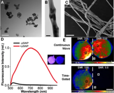
(measured by dynamic light scattering, DLS), and a zpotential of -37 ± 8 mV (Figure S1A,C). Following DNA loading and sealing of the nanostructures with calcium silicate, the average hydrodynamic diameter increased to 217 ± 12 nm and the z-potential decreased to -18.7 ± 2.5 mV (Figure 2A, S1B,C). Hybrid nanofibers with diameters in the range of 423-495 nm were created by spray nebulization, and no significant difference in these dimensions was observed between the different fiber formulations (Figure S2, S3). Transmission electron micrographs revealed pSiNPs embedded within the polymer nanofibers (Figure 2B, S2). Fiber morphology, depicted in scanning electron micrographs (Figure 2C), was similar across the nine fiber formulations investigated in this study (Figure S2).
During DNA loading, a passivating layer of silicon oxide grows on the particle surface, which results in quantum-confined photoluminescence of the silicon nanoparticles.49 This property of
silicon makes it a useful material for imaging and tracking the materials in vitro and in vivo. When excited with a 365 nm LED excitation source, we observed the typical broad photoluminescent emission from the DNA-loaded nanoparticles (Figure S4). Broad photoluminescence emission was maintained when the nanoparticles were loaded into nanofibers composed of PLGA, PLA,
or PCL (Figure 2D, S4, S5). We used time-gated imaging to remove the fluorescence signals from the polymer in order to selectively image the silicon nanoparticles. A 5 μs time gate was used, which allowed visualization of the photoluminescent emission specific to the silicon nanoparticles due to their microsecond emission lifetime.53, 54
Figure 1. Fabrication of hybrid polymer nanofibers containing DNA-loaded porous silicon nanoparticles (pSiNPs). The DNA-based molecular beacon is first
loaded into pSiNPs, which are then added to a chloroform solution of the polymer of interest. The solution is added to an airbrush hopper, and deposited onto a substrate using pressurized nitrogen. The hybrid nanofibers are then collected for analysis.
Figure 2: Characterization of morphology and photoluminescence
properties of hybrid polymer nanofibers containing DNA-pSiNPs. (A) TEM image of DNA-loaded pSiNPs. (B) TEM image of PLGA nanofibers embedded with 2.4% (by mass) of DNA-loaded pSiNPs. (C) SEM image of a collection of PLGA nanofibers impregnated with 2.4% (by mass) of DNA-loaded pSiNPs. (D) Photoluminescence emission spectra (λex = 365nm) of 2.4% (by mass) of
DNA-loaded pSiNPs in PLGA nanofibers and control PLGA nanofibers. Inset images show pSiNP containing PLGA nanofibers (at left), and control PLGA nanofibers (at right). The DNA in the samples contained no fluorescent tag; the emission spectrum is derived from intrinsic photoluminescence of the silicon nanostructure. Sample diameter in each image is ~10mm and the images were acquired using a λex = 365nm excitation source. (E) Time-gated
photoluminescence images of samples from the inset image in (D). The top images are obtained with continuous wave imaging (no time gating); the top left image shows PLGA nanofibers containing DNA-pSiNPs while the top right is control PLGA nanofibers containing no nanoparticles and no DNA. The bottom images are obtained using a 5 μs delay after the λex = 365nm
excitation pulse; at bottom left is PLGA nanofibers containing DNA-pSiNPs while the bottom right image is control PLGA nanofibers containing no nanoparticles and no DNA. Scale bars = 200 nm (A) and (B); 2 μm (C); and 5 mm (E).
Once the DNA-pSiNPs were loaded into the polymer nanofibers, time-gated imaging was utilized to remove background signals caused by autofluorescence and reflection of the excitation source (Figure 2E, S6). Using time-gated imaging, it was possible to achieve a 60-fold increase in the signal-to-noise ratio (SNR) in the 2.4% DNA-pSiNPs-containing PLGA nanofibers compared to control PLGA nanofibers, a 16-fold increase in the PLA nanofibers, and a 120-fold increase in the PCL nanofibers. Without using time-gated imaging, the pSiNPs were essentially indistinguishable from the polymer autofluorescence; the fractional change in SNR from 2.4% DNA-pSiNP nanofibers relative to control nanofibers (containing no pSiNPs) was 0.97, 0.6, and 1.7 for PLGA, PLA, and PCL nanofibers, respectively. This data demonstrates that time-gated imaging allowed identification of the presence of the pSiNP component of the nanofibers, removing the short-lived emission from the polymer matrix and other unwanted background signals (Figure S6).
We next determined DNA release kinetics from the hybrid nanofibers using the model 22-nt single-stranded DNA sequence loaded into the pSiNPs. We initially monitored the DNA release from "free" pSiNPs (not incorporated into a polymer) into aqueous phosphate buffer saline (PBS) solutions maintained at 37° C. The concentration of DNA in solution was monitored at specific time points by UV-Vis spectrophotometry. For this study, the mass loading of DNA in the nanoparticles was set at 4.7 ± 0.4% w/w (defined as mass of DNA divided by total mass of DNA-containing pSiNPs). We found that 90 ± 6% of the loaded DNA was released in the incubation medium in 24 hours, with a burst release over the first 2 hours (88 ± 5%) (Figure S7).
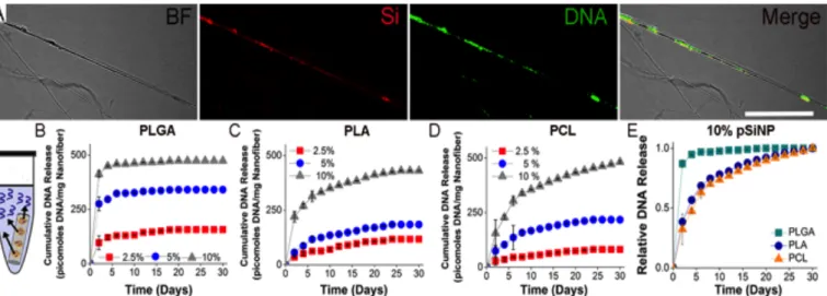
Using a FAM-labeled DNA sequence allowed for visualization of the DNA incorporated into the PCL nanofibers, while two-photon excitation of pSiNPs28, 55-57 was exploited to image the embedded
nanoparticles. The two-photon microscope images revealed co-localization of the FAM-labeled DNA with pSiNPs throughout the nanofibers (Figure 3A). DNA release from PLGA, PLA, and PCL hybrid nanofibers was monitored for a 30 day period. The release study was carried out in PBS, pH 7.4 at 37 °C for the PLGA, PLA, and PCL hybrid nanofibers containing 2.4%, 4.7%, and 9.1% by mass DNA-pSiNPs (for a total of 9 formulations). PBS solutions were changed every 48 hours, and the DNA concentration was determined by UV-Vis spectrophotometry. PLGA nanofibers showed a significant burst release for all three concentrations of pSiNPs, with an average of 76% of the total DNA released from the scaffolds in the first 2 days, and an average of 92% released over the first 10 days (Figure 3B 3E,
S8A). Increasing the concentration of pSiNPs in the PLGA fibers had little effect on the rate of release (Figure S8A), but, as expected, increased the total amount of DNA released from the hybrid
nanofibers (2.4% formulation: 157 ± 15 pmoles mg-1 nanofiber,
4.7% formulation: 340 ± 23 pmoles mg-1 nanofiber, 9.1%
formulation: 473 ± 40 pmoles mg-1 nanofiber) (Figure 3B). After 20
days, no additional release of DNA from any of the three PLGA hybrid fibers analyzed could be detected (Figure 3B, S8A).
DNA release from PLA nanofibers showed a different profile compared with PLGA. No major burst release was observed in this case, with an average of 33% of the total DNA released from PLA scaffolds occurring in the first 2 days and 70% over the first 10 days (Figure 3C, 3E, S8B). Release of DNA was maintained over 30 days in the 9.1% pSiNP scaffolds, whereas DNA release in both the 2.4% and 4.7% pSiNP formulations became undetectable after 24 days (Figure 3C, S8B). As previously observed, a variation in the concentration of embedded pSiNPs had only minor effects on the rate of DNA release (Figure S8B), while increasing the total moles of
DNA released (2.4% formulation: 118 ± 30 pmoles mg-1 nanofiber,
4.7% formulation: 185 ± 33 pmoles mg-1 nanofiber, 9.1%
formulation: 432 ± 67 pmoles mg-1 nanofiber) (Figure 3C).
The rate and duration of DNA release from PCL scaffolds was comparable to that of the PLA nanofibers (Figure 3D, 3E, S9). An average of 35% of total DNA released was observed in the first 2 days, and 73% over the first 10 days (Figure S8C). Release of DNA was maintained over 30 days in the 9.1% pSiNP scaffold formulation, but DNA release from both the 2.4% and 4.7% pSiNP hybrid formulations became undetectable after 24 days (Figure 3D, S8C). As with PLGA and PLA, changing the concentration of DNA-pSiNPs in the nanofibers increased the total amount of DNA released (2.4% formulation: 81 ± 25 pmoles mg-1 nanofiber, 4.7%
formulation: 217 ± 75 pmoles mg-1 nanofiber, 9.1% formulation:
482 ± 51 pmoles mg-1 nanofiber), while producing a minimal effect
on the release rate (Figure 3D, S8C).
The polymer used in the fabrication of the nanofibers had a much more pronounced effect on the rate of DNA release compared to the percent content of pSiNPs in the nanofibers (Figure 3E, S8, S9). While inclusion of 9.1% pSiNPs in both PLA and PCL extended the total duration of measurable release to ~30 days due to the higher overall concentration of DNA, there was only a minor change in the rate of release compared with the hybrid nanofibers containing 2.4% and 4.7% pSiNP-DNA (Figure S8B, S8C).
Figure 3. Location and temporal release of a model 22 nucleotide, single stranded DNA payload from hybrid nanofibers. (A) Confocal microscope images of
PCL nanofibers in bright field (BF), emission from the quantum-confined silicon of the pSiNPs (Si), emission from the FAM-labeled DNA (DNA), and the co-localization of the pSiNPs with the loaded DNA signals (Merge). Scale bar = 10 μm. Diagram of the elution experiment, where DNA was released into a PBS
This journal is © The Royal Society of Chemistry 20xx J. Name., 2013, 00, 1-3 | 4
No DNA release was detected from PLGA nanofibers after 20 days (Figure S8A), indicating that the PLGA scaffolds released DNA from the pSiNPs faster than either PLA or PCL.
When presented as the fractional amount of DNA released as a function of time, the difference between the rate of DNA release from PLGA scaffolds and the PLA or PCL scaffolds is more apparent (Figure 3E, S9). Furthermore, when integrated over the entire 30-day release period in the study, the total percentage of incorporated DNA released from the PLGA scaffolds (80%) was significantly larger than that of either PLA (57%) or PCL (55%) nanofiber groups (Figure S10). This can be attributed to the known greater susceptibility of PLGA to degradation (by hydrolysis of its
backbone ester linkages)58 relative to either PLA or PCL. The more
rapid polymer degradation is expected to lead to more rapid degradation/dissolution of the pSiNP carriers and thus faster release of the loaded DNA. Such differences in hydrolysis rates provide a versatile means of controlling release rate and the ability to vary the quantity of pSiNPs loaded in a given polymer lends control over the total amount of DNA that can be delivered from a scaffold.
We next determined the ability of the hybrid nanofibers to load and release a functional input-responsive DNA nanodevice.
Previously, we have shown that pSiNPs protect oligonucleotides from degradation over 1 hour,59 but the ability of the hybrid
nanofibers to maintain oligonucleotide function over multiple weeks has not been established. As a proof-of-principle we used a DNA molecular beacon, a single-stranded fluorophore-and-quencher-modified DNA sequence with self-complementary ends. In the absence of the target sequence, the molecular beacon adopts a stem−loop configuration that holds its fluorophore/quencher pair in proximity, suppressing emission. Hybridization of a specific nucleic acid target to the loop breaks the stem and separates the fluorophore/quencher pair, increasing the fluorescence signal. In the present work we employed a molecular beacon targeting microRNA-21 (miR-21), one of the most studied oncogenic microRNAs due to its aberrant expression in a multitude of tumors and its potential role as a cancer biomarker.60-63
In order to test if the DNA molecular beacon could maintain its activity upon loading into the pSiNPs (Fig. 4), we first performed an experiment where we observed fluorescence intensity gain when loaded pSiNPs were placed in solution in the presence of miR-21, but without loading the pSiNPs into a polymer matrix. The release of the beacon from the free pSiNPs was monitored for 8 hours (Figure S12); during this period strong signals associated with hybridization of miR-21 to the beacon were observed. Negligible gains in signal were observed in the presence of a control miR-140, demonstrating that the functionality and specificity of the DNA molecular beacon was maintained during loading and release from pSiNPs.
The DNA beacon-pSiNPs were then loaded into the three different polymers, and the activity of the molecular beacon was determined following its release from the hybrid nanofibers. Based on the release rate study presented above, we tuned the concentration of the released DNA to a low nanomolar concentration at the desired time points by adjusting the polymer, the DNA-pSiNP loading parameters, and the volume of PBS release buffer. This allowed for more or less complete hybridization with a 5μM concentration of miR-21 in solution. The PLGA formulation was assayed at a 2-day time point due to the rapid burst release observed from this polymer, while the PLA and PCL formulations were assayed at 10- and 20-day time points, respectively, due to their ability to sustain DNA release over these longer time periods. In the presence of miR-21, the eluents containing the molecular beacon showed ~150% fluorescence signal gain (relative to background prior to addition of the target miR analyte) after 2 days release from PLGA, ~100% fluorescence signal gain after 10 days release from PLA, and ~90% fluorescence signal gain after 20 days release from PCL hybrid nanofibers (Figure 4). Control miR-140 did not induce any significant increase in fluorescence emission from the probe, showing that the molecular beacon maintained its structural integrity and specificity. The differences in signal gain observed with the different polymers is ascribed to partial degradation of the DNA molecular beacon under the elution conditions, but the fluorescence assay clearly demonstrates that the released DNA molecular beacon retains detectable functionality for up to 20 days when loaded into hybrid nanofibers.
Conclusions
This study shows, for the first time, the release of functional DNA beacons from pSiNPs in polymer nanofibers. It also represents the first example of release of functional DNA beacons from common biocompatible polymers. Loading of DNA into such Figure 4. Functional release of a DNA molecular beacon from hybrid
nanofibers. (A) The DNA beacon was loaded into pSiNPs, dispersed into polymer nanofibers by nebulization fabrication, and then the ability of the released DNA beacon to sense its target micro-RNA was determined by fluorescence. (B) Sensing of the miR-21 target, compared to a non-binding miR-140 control, measured by fluorescence signal gain of the released DNA beacon measured from PLGA nanofibers at day 2, from PLA nanofibers at day 10, and from PCL nanofibers at day 2. Here signal gain is quantified as percentage [I(miR)-I(background)]/[I(background)], where I(miR) is fluorescence intensity measured in the presence of the relevant miRNA analyte, and I(background) is fluorescence intensity measured prior to addition of the miRNA analyte.
polymers is difficult due to the incompatibility of DNA with the organic solvents typically used in the polymer processing steps. The results demonstrate the potential for hybrid polymer/porous silicon nanofibers to release functional DNA nanodevices for applications in tissue engineering, biomedical research and for prolonged in situ determination of extracellular microRNAs. For example, molecular beacons released from hybrid scaffolds may have the potential to act as real-time sensors for microRNAs externalized by cells. The fact that the functional DNA molecular beacon employed here as a model system is still detectable after 20 days of release suggests that extracellular microRNAs could be detected in culture over several weeks.
The versatility of the hybrid nanofiber platforms makes them readily customizable. The work here showed that pSiNP loading can be modulated to control the release time and total quantity of the DNA payload. The amount of pSiNPs incorporated in the nanofibers can be set to select a desired amount of DNA cargo. Although not demonstrated here, it is likely that multiple DNA payloads could be loaded into the same nanofiber platform by incorporating different preparations of pSiNPs carrying distinct DNA payloads.
Since the nanofiber hybrids in this study were fabricated using a commercial airbrush, the method is straightforward and relatively inexpensive. Nearly any surface can be directly coated with hybrid nanofibers due to the fact that a high voltage source (as is employed in electrospinning) is not required for nanofiber formation. Imaging of the hybrid scaffolds with the time-gated photoluminescence technique allows for direct visualization of the pSiNPs for applications in bioimaging and in monitoring the degradation of the pSiNP carriers. Additionally, the compatibility with common bioengineering polymers demonstrated here suggests these hybrid systems can be a powerful tool in DNA nanotechnology, tissue engineering, and regenerative medicine.
Acknowledgements
This study was supported by the National Science Foundation under Grant No. CBET-1603177 (MJS). Transmission electron micrographs were taken in the Cellular and Molecular Medicine Electron microscopy core facility, which is supported in part by National Institutes of Health Award number S10OD023527. This project has received funding from the European Union’s Horizon 2020 research and innovation program under the Marie Sklodowska-Curie grant agreement No 704120 (“MIRNANO”). J.K. acknowledges financial support from the UCSD Frontiers of Innovation Scholars Program (FISP) fellowship. A.B. is a Global Marie Sklodowska-Curie Fellow.
Conflicts of interest
MJS holds an appointment as a ‘High-Level Talent' at the Key Laboratory of Organosilicon Chemistry and Material Technology of Hangzhou Normal University, and he is a scientific founder of Spinnaker Biosciences, Inc., a member of the Board of Directors, and has an equity interest in the company. Although one or more of the grants that supported this research has been identified for conflict of interest management based on the overall scope of the project and its potential benefit to Spinnaker Biosciences, Inc., the research findings included in this particular publication may not necessarily relate to the interests of Spinnaker Biosciences, Inc. The
terms of this arrangement have been reviewed and approved by the University of California, San Diego in accordance with its conflict of interest policies.
References
1. N. C. Seeman and H. F. Sleiman, Nat. Rev. Mater., 2018, 3,
17068.
2. S. Modi, C. Nizak, S. Surana, S. Halder and Y. Krishnan,
Nat. Nanotechnol., 2013, 8, 459-467.
3. A. Bertucci, J. L. Guo, N. Oppmann, A. Glab, F. Ricci, F. Caruso and F. Cavalieri, Nanoscale, 2018, 10, 2034-2044.
4. H. Lee, A. K. R. Lytton-Jean, Y. Chen, K. T. Love, A. I. Park,
E. D. Karagiannis, A. Sehgal, W. Querbes, C. S. Zurenko, M. Jayaraman, C. G. Peng, K. Charisse, A. Borodovsky, M. Manoharan, J. S. Donahoe, J. Truelove, M. Nahrendorf, R. Langer and D. G. Anderson, Nat. Nanotechnol., 2012, 7, 389-393.
5. K. E. Bujold, J. C. C. Hsu and H. F. Sleiman, J. Am. Chem.
Soc., 2016, 138, 14030-14038.
6. Q. Jiang, C. Song, J. Nangreave, X. W. Liu, L. Lin, D. L. Qiu,
Z. G. Wang, G. Z. Zou, X. J. Liang, H. Yan and B. Q. Ding, J. Am. Chem. Soc., 2012, 134, 13396-13403.
7. F. A. Aldaye, W. T. Senapedis, P. A. Silver and J. C. Way, J.
Am. Chem. Soc., 2010, 132, 14727-14729.
8. S. Ranallo, M. Rossetti, K. W. Plaxco, A. Vallee-Belisle and
F. Ricci, Angew. Chem., 2015, 54, 13214-13218.
9. J. Chao, D. Zhu, Y. N. Zhang, L. H. Wang and C. H. Fan, Biosens. Bioelectron., 2016, 76, 68-79.
10. C. H. Lu, B. Willner and I. Willner, Acs Nano, 2013, 7,
8320-8332.
11. J. Bath and A. J. Turberfield, Nat. Nanotechnol., 2007, 2,
275-284.
12. L. De Laporte and L. D. Shea, Adv. Drug Deliv. Rev., 2007,
59, 292-307.
13. J. D. Kretlow, L. Klouda and A. G. Mikos, Adv. Drug Deliv.
Rev., 2007, 59, 263-273.
14. S. Lee, G. Jin and J. H. Jang, J. Biol. Eng., 2014, 8.
15. W. C. Low, P. O. Rujitanaroj, D. K. Lee, P. B. Messersmith,
L. W. Stanton, E. Goh and S. Y. Chew, Biomaterials, 2013,
34, 3581-3590.
16. H. Nie, M. L. Ho, C. K. Wang, C. H. Wang and Y. C. Fu, Biomaterials, 2009, 30, 892-901.
17. C. S. Nabzdyk, M. C. Chun, H. S. Oliver-Allen, S. G. Pathan,
M. D. Phaneuf, J. O. You, L. K. Pradhan-Nabzdyk and F. W. LoGerfo, Biomaterials, 2014, 35, 3071-3079.
18. Y. Yang, T. Xia, F. Chen, W. Wei, C. Y. Liu, S. H. He and X. H.
Li, Mol. Pharm., 2012, 9, 48-58.
19. W. W. Y. Yau, P. O. Rujitanaroj, L. Lam and S. Y. Chew, Biomaterials, 2012, 33, 2608-2628.
20. H. Q. Cao, X. Jiang, C. Chai and S. Y. Chew, J. Control. Release, 2010, 144, 203-212.
21. Y. Yang, X. H. Li, L. Cheng, S. H. He, J. Zou, F. Chen and Z.
B. Zhang, Acta Biomater., 2011, 7, 2533-2543.
22. A. Saraf, L. S. Baggett, R. M. Raphael, F. K. Kasper and A.
G. Mikos, J. Control. Release, 2010, 143, 95-103.
23. M. L. Chen, S. Gao, M. D. Dong, J. Song, C. X. Yang, K. A.
Howard, J. Kjems and F. Besenbacher, Acs Nano, 2012, 6, 4835-4844.
This journal is © The Royal Society of Chemistry 20xx J. Name., 2013, 00, 1-3 | 6
24. J. Zhang, Y. J. Duan, D. Wei, L. Y. Wang, H. J. Wang, Z. W.
Gu and D. L. Kong, J. Biomed. Mater. Res. A, 2011, 96a, 212-220.
25. N. Monteiro, D. Ribeiro, A. Martins, S. Faria, N. A.
Fonseca, J. N. Moreira, R. L. Reis and N. M. Neves, Acs Nano, 2014, 8, 8082-8094.
26. J. H. Jang, T. L. Houchin and L. D. Shea, Expert Rev. Med.
Devices, 2004, 1, 127-138.
27. M. J. Wang, J. L. Coffer, K. Dorraj, P. S. Hartman, A. Loni
and L. T. Canham, Mol. Pharm., 2010, 7, 2232-2239.
28. J.-H. Park, L. Gu, G. v. Maltzahn, E. Ruoslahti, S. N. Bhatia
and M. J. Sailor, Nat. Mater., 2009, 8, 331-336.
29. N. Zilony, M. Rosenberg, L. Holtzman, H. Schori, O. Shefi
and E. Segal, J. Control. Release, 2017, 257, 51-59.
30. S. Kashanian, F. Harding, Y. Irani, S. Klebe, K. Marshall, A.
Loni, L. Canham, D. M. Fan, K. A. Williams, N. H. Voelcker and J. L. Coffer, Acta Biomater., 2010, 6, 3566-3572.
31. J. Salonen, A. M. Kaukonen, J. Hirvonen and V. P. Lehto, J.
Pharm. Sci., 2008, 97, 632-653.
32. L. M. Bonanno and E. Segal, Nanomedicine, 2011, 6,
1755-1770.
33. W. J. Xu, R. Thapa, D. F. Liu, T. Nissinen, S. Granroth, A.
Narvanen, M. Suvanto, H. A. Santos and V. P. Lehto, Mol. Pharm., 2015, 12, 4038-4047.
34. Y. D. Irani, Y. Tian, M. J. Wang, S. Klebe, S. J. McInnes, N.
H. Voelcker, J. L. Coffer and K. A. Williams, Exp. Eye Res., 2015, 139, 123-131.
35. A. H. Soeriyadi, B. Gupta, P. J. Reece and J. J. Gooding, Polym. Chem., 2014, 5, 2333-2341.
36. K. Nan, F. Ma, H. Hou, W. R. Freeman, M. J. Sailor and L.
Cheng, Acta Biomater., 2014, 10, 3505-3512.
37. J. L. Coffer, M. A. Whitehead, D. K. Nagesha, P.
Mukherjee, G. Akkaraju, M. Totolici, R. S. Saffie and L. T. Canham, Phys. Status Solidi A, 2005, 202, 1451-1455.
38. S. Kashanian, F. Harding, Y. Irani, S. Klebe, K. Marshall, A.
Loni, L. Canham, D. M. Fan, K. A. Williams, N. H. Voelcker and J. L. Coffer, Acta Biomater., 2010, 6, 3566-3572.
39. J. R. Henstock, U. R. Ruktanonchai, L. T. Canham and S. I.
Anderson, J. Mater. Sci. Mater. Med., 2014, 25, 1087-1097.
40. M. A. Whitehead, D. Fan, P. Mukherjee, G. R. Akkaraju, L.
T. Canham and J. L. Coffer, Tissue Eng. Part A, 2008, 14, 195-206.
41. P. Mukherjee, M. A. Whitehead, R. A. Senter, D. M. Fan, J.
L. Coffer and L. T. Canham, Biomed. Microdevices, 2006, 8, 9-15.
42. D. M. Fan, A. Loni, L. T. Canham and J. L. Coffer, Phys. Status Solidi A, 2009, 206, 1322-1325.
43. D. Kim, J. M. Zuidema, J. Kang, Y. Pan, L. Wu, D. Warther,
B. Arkles and M. J. Sailor, J. Am. Chem. Soc., 2016, 138, 15106-15109.
44. M. H. Kafshgari, B. Delalat, W. Y. Tong, F. J. Harding, M.
Kaasalainen, J. Salonen and N. H. Voelcker, Nano Res., 2015, 8, 2033-2046.
45. K. R. Beavers, T. A. Werfel, T. W. Shen, T. E. Kavanaugh, K.
V. Kilchrist, J. W. Mares, J. S. Fain, C. B. Wiese, K. C. Vickers, S. M. Weiss and C. L. Duvall, Adv. Mater., 2016,
28, 7984-7992.
46. T. Tanaka, L. S. Mangala, P. E. Vivas-Mejia, R.
Nieves-Alicea, A. P. Mann, E. Mora, H. D. Han, M. M. K. Shahzad, X. W. Liu, R. Bhavane, J. H. Gu, J. R. Fakhoury, C. Chiappini, C. H. Lu, K. Matsuo, B. Godin, R. L. Stone, A. M. Nick, G.
Lopez-Berestein, A. K. Sood and M. Ferrari, Cancer Res., 2010, 70, 3687-3696.
47. M. H. Kafshgari, M. Alnakhli, B. Delalat, S. Apostolou, F. J.
Harding, E. Makila, J. J. Salonen, B. J. Kuss and N. H. Voelcker, Biomater. Sci., 2015, 3, 1555-1565.
48. J. M. Zuidema, T. Kumeria, D. Kim, J. Kang, J. Wang, G.
Hollett, X. Zhang, D. S. Roberts, N. Chan, C. Dowling, E. Blanco-Suarez, N. J. Allen, M. H. Tuszynski and M. J. Sailor, Adv. Mater., 2018, 30, 1703309.
49. J. Kang, J. Joo, E. J. Kwon, M. Skalak, S. Hussain, Z. G. She,
E. Ruoslahti, S. N. Bhatia and M. J. Sailor, Adv. Mater., 2016, 28, 7962-7969.
50. W. Tutak, S. Sarkar, S. Lin-Gibson, T. M. Farooque, G.
Jyotsnendu, D. Wang, J. Kohn, D. Bolikal and C. G. Simon, Jr., Biomaterials, 2013, 34, 2389-2398.
51. B. Khalid, X. P. Bai, H. H. Wei, Y. Huang, H. Wu and Y. Cui,
Nano Letters, 2017, 17, 1140-1148.
52. E. Segal, L. A. Perelman, F. Cunin, F. D. Renzo, J.-M.
Devoisselle, Y. Y. Li and M. J. Sailor, Adv. Funct. Mater., 2007, 17, 1153–1162.
53. J. Joo, X. Liu, V. R. Kotamraju, E. Ruoslahti, Y. Nam and M.
J. Sailor, ACS Nano, 2015, 9, 6233–6241.
54. L. Gu, D. J. Hall, Z. Qin, E. Anglin, J. Joo, D. J. Mooney, S. B.
Howell and M. J. Sailor, Nat. Commun., 2013, 4, 2326.
55. E. Secret, M. Maynadier, A. Gallud, A. Chaix, E. Bouffard,
M. Gary-Bobo, N. Marcotte, O. Mongin, K. El Cheikh, V. Hugues, M. Auffan, C. Frochot, A. Morere, P. Maillard, M. Blanchard-Desce, M. J. Sailor, M. Garcia, J.-O. Durand and F. Cunin, Adv. Mater., 2014, 26, 7643-7648.
56. S. Chandra, B. Ghosh, G. Beaune, U. Nagarajan, T. Yasui, J.
Nakamura, T. Tsuruoka, Y. Baba, N. Shirahata and F. M. Winnik, Nanoscale, 2016, 8, 9009-9019.
57. D. Kim, J. Kang, T. Wang, H. G. Ryu, J. M. Zuidema, J. Joo,
M. Kim, Y. Huh, J. Jung, K. H. Ahn, K. H. Kim and M. J. Sailor, Adv. Mater., 2017, 29, 1703309.
58. R. A. Jain, Biomaterials, 2000, 21, 2475-2490.
59. J. Joo, E. J. Kwon, J. Y. Kang, M. Skalak, E. J. Anglin, A. P.
Mann, E. Ruoslahti, S. N. Bhatia and M. J. Sailor, Nanoscale Horiz., 2016, 1, 407-414.
60. A. M. Krichevsky and G. Gabriely, J. Cell Mol. Med., 2009,
13, x-53.
61. S. Volinia, G. A. Calin, C. G. Liu, S. Ambs, A. Cimmino, F.
Petrocca, R. Visone, M. Iorio, C. Roldo, M. Ferracin, R. L. Prueitt, N. Yanaihara, G. Lanza, A. Scarpa, A. Vecchione, M. Negrini, C. C. Harris and C. M. Croce, Proc. Natl. Acad. Sci. U.S.A., 2006, 103, 2257-2261.
62. N. Kosaka, H. Iguchi and T. Ochiya, Cancer Sci., 2010, 101,
2087-2092.
63. Y. Wang, X. J. Gao, F. Wei, X. W. Zhang, J. P. Yu, H. Zhao,
Q. Sun, F. Yan, C. H. Yan, H. Li and X. Ren, Gene, 2014,
TOC Figure
Synthetic DNA-based oligonucleotides are loaded into porous silicon nanoparticles and incorporated into polymer nanofibers. The functionality of these input-responsive nanodevices is retained following release from the hybrid nanofibers.