Software-Defined Radar for Monitoring and Sensing
applications
Contents
i
Contents
Contents ... i
Introduction ... 1
State of the art ... 3
1. Contactless Technologies for Cardiorespiratory Activities Monitoring ... 3
1.1. Traditional Methods for Cardiorespiratory Activities Monitoring ... 4
1.2. Contactless Methods Advantages for Cardiorespiratory Activities Monitoring ... 5
1.2.1. Patient with Serious Skin Impairment ... 5
1.2.2. Sleep Monitoring ... 5
1.2.3. Elderly Monitoring ... 6
1.3. Doppler Radar Employment for Human Cardiopulmonary activity Detection ... 6
2. Radar Principle of Operation and Opportunity Provided by Doppler Effect 8 2.1. Radar Background History ... 8
2.2. Radar Principle of Operation ... 9
2.3. Radar Doppler ... 10
2.3.1. Doppler Effect ... 10
2.3.2. Radar Doppler Waveforms: CW, FMCW, Pulsed ... 12
3. Software-Defined Radio... 16
3.1. Universal Software Radio Peripheral ... 18
Support Theory ... 20
1. Doppler Radar Continuous Wave: Principle of Operation ... 20
2. Doppler Radar CW for Vibrations Monitoring ... 22
3. IQ Signals Modulation and Demodulation in Doppler Radar CW ... 29
Software Defined Doppler Radar for vibrations monitoring ... 43
1. Hardware requirements and devices used ... 43
Contents
ii
1.2. SDR NI USRP-2920 ... 45
1.3. Vertical dipole antenna ... 47
1.4. Impinj A0303 antenna ... 48
1.5. Working frequency choice ... 49
2. Software architecture ... 51
2.1. User interface ... 53
2.2. LabView software modules ... 55
3. Experimental results with classical CW approach ... 59
4. Experimental results with IQ CW approach: breath detection ... 64
5. System performances ... 69
Conclusions ... 71
Appendix – Reconfigurable Reflectarray antenna with high beam scanning 73 1. Problem description ... 73
2. State of the art ... 73
3. Results ... 74
4. Personal contribution to the research ... 76
Introduction
1
Introduction
Mechanical vibrations can result from different phenomena. In many cases, they are desired effects with predictable consequences, but in some cases unwanted oscillations can occur, which interfere with other phenomena, thus causing alterations and unnecessary energy consumption. For these reasons, techniques for vibrations detection are demanded in various areas, such as industrial and civil sectors, but also in remote sensing, safety and security, as well as biomedical engineering applications. Different methods exist for the analysis of kind of phenomena, each one with specific monitoring kind. In the industrial field, the accurate vibration control of rotating machinery plays an important role in the prevention of failures of production plants. In this context, the most commonly used technologies adopt microelectromechanical systems (MEMS) or piezoelectric sensors, which are placed in direct contact with the activity source to be monitored. The mentioned approaches allow to achieve good results [1-3], but being directly subject to mechanical stresses, the sensors are exposed to wear and thus to a progressive alteration during their operation time. Optical methods, implemented with optical fibers placed at small distance from the monitored items, allow to obtain higher reliability [4-7], but similarly to the piezoelectric sensors, they generally offer operating bandwidths in the order of a few KHz [8-9], and require the use of sophisticated signal analyzers to obtain good resolutions in results.
A different solution to the use of punctual position sensors, in the context of vibrations monitoring, is given by the use of remote sensors based on coherent radars. The use of Doppler radar techniques is increasingly popular for monitoring vibrations in the civil context, such as in the remote monitoring of the dynamic characteristics of buildings [10-11]. Similar applications can be found in the biomedical field for the development of physiological sensors able to monitoring breathing and heart rate [12-13]. However, the implementation of a Doppler radar includes the use of a laboratory test equipment or custom hardware on printed/integrated circuits, and this makes the system rather bulky and expensive.
In this work, a completely new approach for Doppler radar implementation, fully based on a software-defined platform, is proposed. This alternative, flexible and low cost solution can be obtained through the use of an SDR transceiver [14-15], which leads to implement a multi-function radar, known as Software Defined Radar
Introduction
2
(SDRadar) [16-17], composed by RF hardware modules fully reconfigurable via software. An SDRadar system allows to realize most of the basic operations (e.g. modulation, demodulation, filtering and mixing) by the simple use of programmable software modules, instead of specific hardware components [15], thus leading to a faster and cheaper development and manufacture, as compared to conventional custom radars [18]. The choose of a software instead of hardware platform is just performed in this work to overcome the limits imposed by electronic circuitries. As a matter of fact, while architectonic structures limit the performances in terms of detectable frequency, due to the specific (fixed) adopted hardware, our solution is strongly flexible. In particular, SDRadar is fully able to satisfy the frequency detection requirements, even in the presence of very low values (e.g. typical of heart oscillations), by simply changing via software the bandwidth, and thus the frequency detection range and the resolution. Even if many PCB and chip level realizations of custom radar sensors can be actually found at low price, the main benefit deriving from our SDRadar solution is the demonstration of using a programmable none-custom-designed RF equipment for radar motion detection study. This will enable researchers without radio frequency/ microwave circuit background to study the signal processing, system consideration, and potential applications for microwave motion sensors. The high flexibility of the proposed software architecture, essentially related to the possibility of carrying out fast detections without the need to use wearable sensors or instruments in direct contact with the item to be monitored, makes this type of systems suitable to the detection of vibrations originating from different phenomena, as those generated by industrial plants. Moreover, the proposed contactless approach can be successfully adopted for the monitoring of vital parameters, with application in security systems based on the body motion detection, or in those emergency situations for the detection of people buried under critical conditions.
State of the art
3
State of the art
1.
Contactless Technologies for Cardiorespiratory Activities
Monitoring
The contactless detection of the human cardiopulmonary activity is one of the most promising solutions for sleep monitoring, post-operative surgery patients observation, domiciliary healthcare as well as applications in the safety and security field for the search and the rescue of people in emergency situations. Without contact and without some monitored subjects preparation, the health control of people suffering from chronic illnesses is significantly simplified also for the patients outside of hospital facilities. In this context, the Doppler radar used for the vital signs remote sensing has gained considerable popularity from the scientific community. The possibility to detect the vital signs, in a non-invasive and continuous way Doppler radar, has been demonstrated through a series of applications [19]. Typically, the human cardiopulmonary activity monitoring is realized through the contact sensors employment, such as the electrodes used in the electrocardiogram (ECG). In many situations, the use of these sensors is not welcome or it is not possible, as for children born premature or in those patients having serious skin impaired as the burn patients. On the other hand, contact sensors with a continuous use may suffer from a degradation, thus producing annoying cutaneous irritations, and so making ineffective and impracticable a long period monitoring.
There are manifold contexts in which a continuous and long period monitoring of vital signs could be necessary: when addressed to elderly people, or those people suffering from chronic pathologies or with sleep disorder, remote sensing of the vital signs can offer many benefits. A speedy identification of anomalies in the physiological parameters of patients may encourage an effective intervention from specialist medical staff, able to prevent heart failure with fatal consequences. The possibility to monitor, in a continuous way, the cardiopulmonary activity of these patients through contactless sensors, can have therefore an important impact in the healthcare field in terms of mortality reduction of mortality and cost reduction [20].
State of the art
4
1.1. Traditional Methods for Cardiorespiratory Activities Monitoring
When the direct access to the patient is possible, the first option is the human supervision of cardiopulmonary function. While the ECG is certainly the 'gold' standard for the cardiac activity monitoring, an equivalent standard does not exist for the respiratory monitoring. Although the respiratory frequency is a highly premonitory parameter of patient physiological instability, its measure is often neglected for the lack of simple application monitoring methods. Typically, in fact, the respiratory frequency is manually monitored by a sanitary operator, through the visual and direct verification of the thoracic excursions.
The techniques currently used for the respiratory activity verification can be grouped into three categories: oxygen saturation measurement, airflow measurement, and respiratory movements measurement [21]. The oxygen saturation is measured through the pulse oximeter, which through a probe emitting light at different wavelength, it is able to establish how much hemoglobin is oxygen saturated. Instead, the direct airflow measurement is effected through a spirometer set in a mouthpiece or in a mask. The spirometer estimate the air volumes inspired and expired in time, but it is a tool a little used because its employment imposes an elevated effort to the patient. Airflow indirect measurements can be carried out through temperature sensors placed in proximity to the nose and the mouth. The reconstruction can be rather precise but its implementation is really annoying for the patients. The respiratory movements measurement, instead, can be carried out with various methods, by monitoring, through strain gauge or other sensors typologies, the bodily volume variation. All techniques have some types of advantages as well as disadvantages. The pulse oximeter may indicate the presence of respiratory problems, but it is not able to provide the respiratory frequency. The airflow measurements can be very accurate, but they interfere with the normal respiratory activity. The respiratory movements measurements, instead, force the patient to the immobility or to the use of wearable sensors or electrodes that degrade itself with the use.
Regarding the cardiac activity, the standard verification method, as stated above, is the ECG. This method estimates the heart muscular activity through its electric activity monitoring. The electric waves causing the heart contraction, in fact, are intercepted by electrodes placed in different chest parts and from these the heart rhythm and possible critical issues in the different heart parts can be derived. Apart from ECG, other less invasive and simpler methods exist to measure the cardiac activity. Piezoresistor or optical or pressure sensors can be adopted to monitoring the pulsations or the blood pressure, thus estimating the heart activity. All methods use, however, contact or wearable sensors.
State of the art
5
1.2. Contactless Methods Advantages for Cardiorespiratory Activities Monitoring
The possibility to identify vital signs such as heart pulsation and respiration can be extremely useful in different circumstances in which no direct access to the subject under investigation is possible. Skin irritations, limitations in the respiration activity and contact with electrodes are conditions that in some typologies of patients, such as in the burn subjects, can be particularly critical. Beyond the health care scope, a lot of possible remote sensing applications of the vital signs are imaginable in the safety and security, for applications 'Through the wall', in search and rescue operations.
1.2.1. Patient with Serious Skin Impairment
For patients with very sensitive or extremely compromised skin, the development of reliable non-invasive techniques for the vital signs monitoring can have meaningful benefits. These situations are manifold. In the pediatric intensive care unit, the newborns often suffer from scratches and cutaneous lesion [22], due to adhesive bandages that fix the ECG electrodes. Similar difficulty situations occur in the case of fire victims. The sanitary operators often have difficulty to monitoring the heart activity of this type of patients, because they don't succeed in finding enough skin (which is not burnt), to apply the electrodes [23]. For these patients, the continuous heart activity monitoring becomes very difficult and often the esophageal echocardiogram is forced to have an idea of the cardiac system state. For the described patients typologies, it is evident that the possibility to a contactless monitoring of heart and respiratory frequency, would lead to significant advantages.
1.2.2. Sleep Monitoring
Cardiopulmonary activity is the principal parameter used in the sleep disorders study. It is widely recognized that the sleep quality and quantity have a meaningful impact on the learning, on the memory, on the cardiovascular system health, on the metabolism, and on the immune system. The apnea in the sleep (OSAS. 'Obstuctive Sleep Apnea Syndrome') is the most diffused sleep disorder and the sufferers are mostly overweight men older than forty, but the problem may affect at all ages, including the pediatric age. For apnea means the lack of airflow for great of ten seconds. The OSAS has a lot of negative consequences, among them the daytime sleepiness, the increased risk of having accidents with motor vehicle or with working equipments, the hypertension, cognitive difficulties, psychiatric nature problems.
State of the art
6
Currently, the sleep monitoring is achieved by polysomnography, that consists in the simultaneous measurement, during the sleep, of different physiological and respiratory parameters. This practice require specific laboratory instrumentation, expensive and bulky [24], and this discourages the sleep clinics diffusion pushing downward the number of patients suffering from OSAS that receives correct treatments. The possibility to make contactless monitoring could resolve the difficulties identified and may favor the diffusion of specialist laboratories for the sleep disorder treatment, having a positive effect on the road and job accidents reduction to them referable.
The sleep apnea problems, together with other physiological parameters anomalies such as the bradycardia, are part besides, of the symptoms heralding sudden infant death syndrome (SIDS) [25]. Also for this events type, the babies sleep monitoring through contactless techniques could be extremely useful to favor a rapid intervention of healthcare professionals against harmful effects.
1.2.3. Elderly Monitoring
The elderly population, beginning from the second half of the last century, is constantly growing. It is well known that with age, older people facing the mobility reduction and the presence of equilibrium problems. These factors expose the elderly population to an elevated risk of domestic accidents caused by falls. Through contactless monitoring of the cardiorespiratory activity, would be possible to effect, in the home, continuous and long-term monitoring targeting elderly people, capable to identify conditions that requiring the healthcare professionals intervention.
1.3. Doppler Radar Employment for Human Cardiopulmonary activity Detection
The Doppler radar development for the human cardiopulmonary activity detection can conduct to the platform implementation able to effect the physiological parameters monitoring in continuous and contactless way. The Doppler radars lend themselves to detecting heart and respiratory activity also through clothes, walls or rubble. The heart and respiratory activity detection can occur simultaneously and independently.
The Doppler Continuous Wave (CW) radars ability to detect the cardiopulmonary activity has been known about 1970s [26]. In the 1980s this possibility has also been valued for Frequency-Modulated-CW (FMCW) radars and
State of the art
7
Ultra-Wideband systems (UWB) [27-28]. The microwaves ability to effect non-invasive monitoring in the medical-diagnostic field had, in the last decades, an increasing recognition, culminated with a recent approval from the 'Food-and-Drug-Administration' (FDA). The microwaves technologies and microprocessors diffused use, within the domestic communications, drove downward this type of components costs, by making it possible the radar development for cardiopulmonary activity monitoring to more advantageous economic conditions in comparison to those offers from the traditional instrumentation.
The heart and respiratory activity monitoring, through microwaves radar, has been shown from the second half of the 1970s. In these first research jobs, the two phenomena were separately measured and this required, to the subject under observation, to hold the breath during the heart activity measurements [29]. The system used, composed by an oscillator in X band and from two horn antennas centered at the chest superior part of the subjects subject to monitoring, was able to detect the not anesthetized rabbit respiratory frequency placed to a distance of 30 cms [26]. The same system has been employed as apnea detector and it has been tested in a scenery composed by a rabbit and two anesthetized and intubated cats. This system has been able, therefore, to detect artificially induced apnea and hyperventilation conditions on the animals under observation [30].
In the 1980s and 1990s, the development of more evolved transceivers equipped with microprocessors and integrated analogical hardware, has allowed separating the weakest cardiac signal detection from the respiratory movement detection, allowing the simultaneous monitoring of the two activities, without forcing the subjects under observation to hold the breath [31]. Systems based on these transceivers use have been employed for the athletes cardiac and respiratory frequency detection [32], for buried people detection [33] or for people behind wall detection [34]. The receivers in quadrature use has allowed, besides, to resolve the 'Null Point' problem [35].
The research efforts, in the last decade, are finally moved toward the strong, light, few bulky and characterized by a low energy consumption systems development, able to carry out accurate detections to long distance, to implement portable and economic applications. The more successful use of this type of technology concerns the healthcare applications.
The experimented employments have been manifold. The use of Doppler radar has been tested for babies monitoring with the purpose to prevent SIDS events [36]. The application incorporated Doppler radar into the classical baby monitor; if this didn't detect respiratory movements in the baby for an interval of 20 sec, an alarm alert the parents. Similar solutions have been developed for a long time monitoring of the sleep apnea [37]. Different studies in sanitary area have shown the ability,
State of the art
8
through this technology, to effect the respiratory activity monitoring in complementary or substitutive way to the conventional technologies [38].
The interest in this type of applications has pushed the scientific community to develop different architectures, optimized for different operational contexts. Various techniques are been experimented for isolating multiple target [39] and different hardware implementations hardware, with laboratory equipment [40] or with specific integrated circuits [41], have shown that this technology can be used by specialized research staff, but also from generic consumers without specific competencies in the microwaves or in RF field.
2.
Radar Principle of Operation and Opportunity Provided by
Doppler Effect
Radar is the acronym of 'Radio Detection And Ranging.' A radar system transmits an electromagnetic signal and observes the echo reflected by one or more objects, to get information on the presence, the position and the motion of the target intercepted. The principal functions offered by the first radar prototypes of the 1920s were essentially related to the possibility to detect some targets and to estimate the distance to which these were displaced. The scientific and technological progress has allowed, in time, to equip these systems with detection ability increasingly accurate, able to monitor more targets in simultaneously and able to track them through estimation on their speed, direction, and altitude.
2.1. Radar Background History
The radar systems radar has originally been conceived for military applications for hostile armed vehicles overseeing and control. The current applications have been extended to the civil use and they include navigation systems for vehicles aircrafts, ships, spatial nacelles, collision avoidance systems for cars, precipitations monitoring applications, radio astronomy and geologic observation applications, together with the classical military applications for aerial defense as the missile defence systems or the guidance systems for missile. The way for the electromagnetic waves use has been made from James Clerk Maxwell, that formulated the unified theory of the classical electromagnetism around 1860 and from Heinrich Hertz that it was the first one to show the radio waves transmission and reflection around 1880. The reflected electromagnetic waves for individualizing objects has not been used until the early 1900s, when through the
State of the art
9
Doppler effect, described by Christian Andreas Doppler in 1842 [42], Christian Huelsmeyer and Nikola Tesla individualized distant moving boats. In the 1920s, Albert Hoyt Taylor of the 'Naval Research Laboratory' developed a radar for the naval tracing, installed on board of a boat in 1937 [43]. In 1924, Sir Edward Victor Appleton used the technology now known as 'Frequency-Modulated Continuous Wave', FMCW, to show the ionosphere existence and to measure its distance [44]. A big contribution in the radar systems evolution has been surely brought by Sir Robert Alexander Watson Watt, which developed, on behalf of the 'British Meteorological Office', the first radar for meteorological purposes. Particularly Sir Watt realized a radar able to detect the presence of distant stormy phenomena. All the Sir Wat studies carried him to have a decisive role for the Second World war results. On behalf of the 'British War Office' Sir Watt developed, in fact, a radar system able to individualize hostile military airplanes before these were visible, obtained the patent for the first pulsated radar system. Beginning from 1939, and throughout the Second World war, Great Britain prepared a series of radar stations along its coasts to detect the aerial or maritime vehicles possible arrival. During the war technology had a significant evolution and the first systems equipped with display were also predisposed to a rapid and simplified radar signals reading.
Finished the Second World war the radar technology was, therefore, used in various civil sectors coming so, to our days, present in a variegated applications range.
2.2. Radar Principle of Operation
When a radar system transmits a radio frequency (RF) energy impulse, a small portion of this is reflected by the intercepted objects and it comes back following the same path. Since the electromagnetic waves speed in free space is equal to the light speed, it is possible to derive the intercepted objects distance by the measurement of the time interval between the transmission and the receipt, by the radar, of the reflected signal. If the radar system is also able to measure the reflected electromagnetic wave frequency, it is possible to derive the object speed from the frequency shift suffered by the transmitted signal. The principal advantage of the electromagnetic waves use, particularly if they are located in the microwaves spectrum, is represented by their ability to penetrate clouds, smog, and dust, detecting also nonvisible objects [43].
As shown in Figure 1, a radar system is macroscopically composed by a transmitter, an antenna, a receiver and a unity devoted to the signals elaboration. The transmitter produces the electromagnetic wave, and through amplifiers, it gives them the necessary power. An antenna, typically an electronic scanning antenna
State of the art
10
array, focus the energy in the target direction. The receiver picks up the reflected signal, filters it from noises and move it in baseband to forward it to the elaboration unity devoted to the information extraction.
Figure 1 - Radars principle of operation
In principle, the radars can operate at any frequency but the practical implementation, in terms of antenna dimension, transmitted power, distance from the target and resolution, impose some constraints on the working frequency. The frequency range conventionally employee for RF applications is from 3 KHz to 300 GHz, but the 'IEEE Standard for Letter Designation for Radar-Frequency Bands' has identified the 3 MHz-300 GHz range as a useful band for radar applications.
2.3. Radar Doppler
The Doppler radars are typically used for individualizing objects in movement and to estimate their speed. The most common applications of Doppler radars concern the meteorological images extraction and the vehicles speed detection. Another typical context in which the Doppler radars are used is the safety and security context. In these applications the Doppler radars are used for fixtures movements or opening detection to indicate possible intrusions.
2.3.1. Doppler Effect
The Doppler effect, or Doppler shift, is the frequency variation of the received wave when the observer is in movement in comparison to the same. This
State of the art
11
phenomenon was discovered by the German physicist Christian Doppler and concerns all the wave types, included the sound waves, light waves, and electromagnetic waves. If the sound frequency coming from a source maintains constant, and both the source and the observer stay in their position, the sound wave maintains the original frequency and the observer it receives the same number of produced wavefronts. If instead the source or the observer reach toward, the observer perceives a higher frequency sound because, in the same time frame, he collects more wavefronts. In analogous way, if the source or the observer moving away, the observer perceives a lower frequency sound because he collects fewer wavefronts.
Considering 𝑅 as target distance and 𝜆 as wavelength, the number of wave collects, coming from the target and intercepted by the radar will be 2𝑅 𝜆⁄ . To every wavelength corresponds a 2𝜋 radians variation. The total phase delay, in roundtrip it is therefore equal to that shown in eq. (1).
𝜙 = 2𝜋 ×2𝑅 𝜆 =
4𝜋𝑅
𝜆 (1)
The target movement in relation to the radar position will produce therefore a phase variation. Deriving with respect the time, as shown in the eq. (2), you get, therefore, the speed with which the phase changes and therefore the angular frequency
𝜔𝑑=𝑑𝜙 𝑑𝑡 = 4𝜋 𝜆 𝑑𝑅 𝑑𝑡 = 4𝜋𝑣𝑟 𝜆 = 2𝜋𝑓𝑑 (2)
where 𝑣𝑟 = 𝑑𝑅 𝑑𝑡⁄ indicates the radial speed (m/s) or the speed with which the distance varies in time. If, as shown in Figure 2, the angle between the target vector speed and the radar line of sight of is 𝜃, then radial speed is that shown in the eq. (3)
𝑣𝑟 = 𝑣cos𝜃 (3)
where 𝑣 is the speed or the vector magnitude. From eq. ((2) may be derived the Doppler shift as shown in the eq. (4)
𝑓𝑑=
2𝑣𝑟 𝜆 =
2𝑓𝑡𝑣𝑟
𝑐 (4)
where 𝑓𝑡 is the transmitted signal frequency by the radar and 𝑐 is the light speed
State of the art 12
v cos v v r RFigure 2. Target movement speed in relation to the radar
2.3.2. Radar Doppler Waveforms: CW, FMCW, Pulsed
2.3.2.1. Continuous Wave
A CW radar, is a system that in continuous way transmits and receives a very narrow band signal. The transceiver CW is characterized by a very simple topology composed by a transmitter and a receiver heterodyne or homodyne. As the transmission and the receipt are continuous, these systems do not require a control that selects the receipt and transmission channel as in the pulsated radars case [45]. A CW radar may be equipped with a single antenna accompanied by a duplexer or by a circulator to isolate the transmitted signal and the received one, or it can use separate antennas to transmit and to receive. Since the band is extremely narrow, the filters used in the different stadiums are very simple, and the Doppler shift results very evident. Theoretically, a CW radar system may recognize, in nonambiguous way, the rate of a target placed at any distances with any speeds.
The principal disadvantage of the CW radars is represented by the losses between the transmitter and the receiver. A portion of the transmitted signal, because of the losses, pairs in the receiver through the circuitry or directly through the antennas. These losses inject in the receiver a big signal characterized by the same frequency of the transmitted one, that is not related to any targets presence. The presence of others signals at the same frequency of the transmitted one may also be linked to other objects that don't result of interest or from static target. These not desider signals cause a DC component and low-frequency noise that are not upstream eliminable.
A CW radar system with single-ended receiver is not able to distinguish if the target is in approach or in leaving because it is not able to preserve the shift direction
State of the art
13
information in the conversion phase from the bandpass to the baseband. To remedy this problem, coherent heterodyne or in quadrature homodyne receivers are used, which succeed in estimation of the target movement direction [44].
2.3.2.2. FMCW
A CW Doppler radar is able to determine the target speed by identifying CW received signal frequency shift. To the purpose to not only detect the speed but also the target range, is necessary that the used signals are syncronized in some form, in such way to be been able for measure the delay between the transmitted signal and the received one. To resolve this problem, it is possible to introduce different CW signals modulation types as the FMCW modulation, 'Stepped Frequency Continuous Wave' (SFCW) modulation, 'Coded Modulation' (CM), 'Noise Modulation' (NM), 'Synthesized Pulse Modulation' (SPM), 'Holographic Modulation' (HM) or 'Amplitude Modulation' (AM) [46].
The modulation in frequency more commonly used for the systems FMCW is that triangular, in which the frequency variations are gradual. In Figure 3 is shown a frequency modulation in an FMCW radar example. The transmitted signal is represented by the continuous line, while the dotted line shows the backscattered signal frequency received by a static target. The frequency excursion ∆𝑓 is the FMCW signal band and determines the maximum obtainable accuracy on the distances detected, while the repetition frequency of the triangular modulation 𝑓𝑚 determines the maximum unambiguous range. The reflected signal reaches the radar with a delay, by comparison to the transmission, expressed by the eq. ((5)
𝑇 =2𝑅
𝑐 (5)
where 𝑅 is the target range. The received signal and the transmitted one are multiplied in a mixer that produces a signal out with a 𝑓𝑏 frequency equal to the frequencies difference of the mixed signals.
State of the art
14
Figure 3 - Transmitted and received signal, and beat frequency individualized by a FMCW radar for a static target (courtesy of [47])
In the example shown in Figure 3, the frequency shift 𝑓𝑏 is entirely due to the target range 𝑅 effect, express as 𝑓𝑟. From simple geometric considerations can be determined 𝑓𝑏 as shown in the eq. (6).
𝑓𝑏 = 𝑓𝑟=4𝑅𝑓𝑚∆𝑓
𝑐 (6)
With the presence of moving target, 𝑓𝑏 results determined, as well as by 𝑓𝑟, also from 𝑓𝑑 that represents the due move to the Doppler effect. In this case, the frequency difference is 𝑓𝑟+ 𝑓𝑑 during a half period of modulation and 𝑓𝑟− 𝑓𝑑
during the other half period, as shown in Figure 4. The target range may be obtained as the average among these two frequencies in the 1 𝑓⁄ period. 𝑚
State of the art
15
∆𝑅 = 𝑐
2∆𝑓 (7)
Figure 4 - Transmitted and received signal, and beat frequency individualized by a FMCW radar for a moving target (courtesy of [47])
An application example is described in [48], where a FMCW radar system has been used as altimeter on board of an aircraft.
2.3.2.3. Pulsed Doppler Radar
The pulsed radars are the radar category mostly used. A pulsed radar transmits narrow impulses, characterized by elevated power, to a repetition frequency, PRF, constant; from the analysis of the time employed by the impulse reflected by the target to return back, the intercepted target range can be reconstructed. The pulsed radars that use the Dopper effect for the moving target detection are called "Moving Target Indication" - MTI radar or pulsed Doppler radar [48]. The technique mostly used, for the range reconstruction with this radar typology, provides for measure the delay between the transmitted impulse and the reflected impulse receipt. Since the RF energy is propagated with light speed, the 𝜏 delay between the impulse transmission and receipt has shown in the eq. (8).
𝜏 =2𝑅
𝑐 (8)
The principal pulsed radars advantage in comparison to the CW or FMCW radars is the possibility to have quite separate times of transmission and receipt, allowing to avoid involvement of the weak echoes receipted caused by the losses, in the transmitter, of the strongest transmitted signals.
State of the art
16
If the impulse duration is sufficiently long and the target speed is enough elevated, it is possible, also in the pulsed radars, to detect the frequency shift for Doppler effect through the single impulse duration variation and the impulses sequence PRF variation.
3.
Software-Defined Radio
Generally, radio systems have been engineered to process a specific signal or waveform. Single-function radio system that operate in a known and fixed environment are easy to optimize for performance, size, and power consumption. Most home radio systems, at a superficial analysis, appear to be single function but many of these devices are actually quite flexible and support different waveforms. The software-defined radio’s (SDR) main characteristic is, therefore, its ability to support different waveforms by using the same hardware platform in which some or all of the physical layer functions are software defined. An ideal and basic block diagram of this type of radio systems is shown in Figure 5, in which the software running on a custom or general purpose microprocessor selects one of the system function available to it, with this functionality no explicitly included by the designers.
Figure 5 - Ideal software-defined radio system: (a) TX stage, (b) RX stage (courtesy of [49])
The digital samples are then converted directly into an RF signal and sent to the antenna. The transmitted signal enters the receiver at the antenna, is sampled and digitized, and finally processed in real time by a general purpose processor. Ideally, the SDR hardware should support any waveform at any carrier frequency and any bandwidth, but in reality there are some limits, such as the difficulty to tune antennas dynamically. The band of interest extension also requires wideband antenna, and if this are available, places high demands on the RF front end, the A/D converters and the real-time digital signal processing.
Some of the most significant advantages and applications are summarized below.
Interoperability. An SDR can seamlessly communicate with multiple incompatible radio system or act as a bridge between them.
State of the art
17
Optimized use of resources according to the operational context. An SDR can use the appropriate waveform to maximize the systems performances for every scenario. For example, a low-power waveform can be used if the system battery is running low, or high-throughput waveform can be selected to quickly download a large file.
Cognitive radio. An SDR can reuse the frequency in opportunistic way. If a specific band is momentarily available, an SDR can use the spectrum until the owner comes back. This technique dramatically increase the amount of available spectrum.
Reduced obsolescence. An SDR can be upgraded in the field to support the latest communications standards, saving the new hardware and its installation cost. Lower cost. An SDR can be adapted for multiple markets and applications.
Economies of scale have a cost of each device reducing effect.
Research and development. An SDR can be used to implement many different waveforms for real-time performance analysis. Large trade-space studies can be conducted much faster than through simulations.
The technology is not without disadvantages and ambiguity.
Device cost for simple application. This aspect is particularly important for high-volume, low margin consumer products, for example a garage or car door remote opener key fob or AM/FM radio receivers. These extremely simple devices are also high-volume and potentially very low cost. An SDR is necessarily more complex than these single-function radio and also employing SDR chip for the above applications, the increased market volume would not drive chip cost sufficiently down.
Power. In an SDR system there are two sources contributing to higher power consumption: increased processor complexity and higher mixed-signal/RF bandwidth. FPGA used to implement flexible signal processing and wideband ADCs/DACs consume more power than ASIC microprocessor and narrowband ADCs/DACs generally used in single-function radio.
Complexity. An SDR requires additional complexity compared to a standard radio system. It takes more engineering effort to develop software and firmware to support flexible waveform than to support fixed one and it impacts on time and cost to implement the SDR platform.
State of the art
18
3.1. Universal Software Radio Peripheral
The Universal Software Radio Peripheral (USRP) introduction drive down the SDR device cost from tens of thousands dollars to hundreds dollars. The USRP is a commercial product developed since 2010 by Ettus Research, a little research company, that was then acquired by National Instruments (NI). USRP was released at about the same as GNURadio with drivers source code and mixed-signal circuit board in the public domain but RF circuit boards are proprietary. USRP is currently supported in MathWorks Simulink and NI LabView.
The first USRP model is equipped with an USB 2.0 interface and provides up to 30 MHz of instantaneous bandwidth for about $1000 (Figure 6).
Figure 6 - First USRP model (USRP1)
The second USRP model is equipped with a gigabit Ethernet interface allowing it to increase instantaneous bandwidth to 50 MHz at about $2000 (Figure 7).
Figure 7 - Second USRP model (USRP2)
Different daughter boards are used to support a range of frequencies from DC to 6 GHz. Each USRP supports two receive and two transmit channels and multiple USRPs can be synchronized to provide more coherent channels. The USRP consist of an FPGA, 100 MHz-class A/Ds and D/As, RF daughter boards and an interface to the host computer (Figure 8). The FPGA is used to channelize the data and interface to the host port.
State of the art
19
Figure 8 - USRP block diagram
The FPGA implements digital frequency shifting and rate change. The FPGA source code can be modified to implement more sophisticated processing. Some or even all of the processing for the SDR application can be implemented on the FPGA to achieve higher throughput than it possible with a PC [50].
Support Theory
20
Support Theory
1.
Doppler Radar Continuous Wave: Principle of Operation
The wave reflected by a moving object, whatever its physical nature is, suffers a frequency shift, compared to the incident wave on the same, proportional to the object speed. This phenomenon, known as effect Doppler, is exploited in the radars to individualize moving target and eventually to monitoring their motion. You suppose to use a transceiver, working in the microwaves spectrum, able to transmits a monochrome signal with 𝑓0 frequency, characterized by a 𝜃(𝑡) phase noise (eq. (9)).
𝑇𝑥(𝑡) =cos[2𝜋𝑓0𝑡 + θ(𝑡)] (9)
The generated signal, during propagation, intercepts an objective to a 𝑑0 nominal distance that causes its backscattering. The backscattered signal, recovered by the receiver, results attenuated by 𝐿 propagation losses factor and is correlated to the transmitted signal through the 𝜏(𝑡) delay (eq. (10)). This delay induces, in the received signal (eq. (11)), a frequency shift, known as 𝑓𝑑 Doppler frequency,
linearly related to the intercepted object radial speed 𝑣𝑟, as shown in the eq. (12).
𝜏(𝑡) =2𝑑0 𝑐 + 2𝑣𝑟 𝑐 𝑡 (10) 𝑅𝑥(𝑡) = 𝐿 ⋅ 𝑇𝑥(𝑡 − 𝜏(𝑡)) = 𝐿 ⋅cos[2𝜋𝑓0(𝑡 − 𝜏(𝑡)) + θ(𝑡 − 𝜏(𝑡))] = = 𝐿 ⋅cos[2𝜋𝑓0𝑡 − 4𝜋𝑓0𝑑0 𝑐 − 4𝜋𝑓0𝑣𝑟 𝑐 𝑡 + 𝜃(𝑡 − 𝜏(𝑡))] = = 𝐿 ⋅cos[2𝜋 (𝑓0− 2𝑣𝑟 𝜆 ) 𝑡 − 4𝜋𝑑0 𝜆 + 𝜃(𝑡 − 𝜏(𝑡))] = = 𝐿 ⋅cos[2𝜋(𝑓0+ 𝑓𝑑)𝑡 − 4𝜋𝑑0 𝜆 + 𝜃(𝑡 − 𝜏(𝑡))] (11) 𝑓𝑑= −2𝑣𝑟 𝜆 (12)
Through the received and the transmitted signals treatment, it is possible to extract the intercepted object speed information. In fact, when they are multiplied through a mixer and then filtered, through a pass-low filter, the baseband signal in resultant exhibits a frequency equal to 𝑓𝑑 therefore linearly related to the target speed (Figure 9).
Support Theory 21 r v t Tx t Rx 2f0t cos 0 f 0 f d f f 0 d d f f f,2 0 d f N / 0 f d f f 0 T f S f
Figure 9 - Doppler Continuous Wave (CW) radar architecture
Out of filter, after the interest signal analogical-digital conversion, it is possible to extract the 𝑓𝑑 frequency shift through a Fast Fourier Transform (FFT) algorithm. Finally, by eq. (12), it is possible to reconstruct the intercepted object radial speed. The Doppler CW radar described is characterized by some important parameters:
𝐵 is the receiving antenna bandwidth;
𝑓𝑇 it is the low-pass filter cutoff frequency. This parameter limits the maximum detectable speed and is in relationship with receiving antenna bandwidth by eq. (13);
𝑓𝑇 ≥
𝐵
2 (13)
𝑓𝑆 is the sampling frequency of the analogical-digital conversion circuit
and it must be chosen so as to satisfy the Nyquist-Shannon sampling theorem according to the relationship expressed by the eq. (14);
𝑓𝑆 ≥ 2𝑓𝑇 (14)
𝑇0 is the time period of every acquisition interval;
𝑁 expresses the collected samples number in an 𝑇0 acquisition interval. The collected samples are subsequently transferred from the analogical-digital conversion circuit to the FFT processing block. The samples number can be evaluated by the eq. (15).
𝑁 = 𝑇0𝑓𝑠 (15)
There are some useful relationships useful to bind these radar parameters to its characteristics in resolution and maximum detectable frequency terms. From eq. (15) it is possible to determine the resolution (eq. (16)), while the maximum detectable frequency is determined beginning from the low-pass filter cut-off frequency and from the receiving antenna bandwidth (eq. (17)).
Support Theory 22 Δ𝑓 =𝑓𝑠 𝑁= 𝑓𝑠 𝑇0𝑓𝑠= 1 𝑇0 (16) 𝑓𝑚𝑎𝑥 = 𝑓𝑇 =𝐵 2 (17)
By eq. (12) the speed resolution can be derived (18) and the maximum detectable speed (19). Δ𝑣= 𝜆 2𝑇0 (18) 𝑣𝑚𝑎𝑥=𝜆𝐵 4 (19)
2.
Doppler Radar CW for Vibrations Monitoring
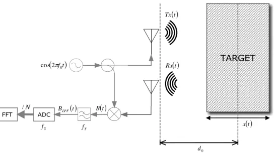
The architecture presented can be used in different application contexts than those above. This type of radar, in fact, characterized by a very simple, sturdy and reliable architecture, based on a single local oscillator and narrowband signals, can be exploited for the oscillatory motions monitoring. In this case, hypothesizing in the reference scenario the presence of only one oscillating object oscillations, it is possible to individualize two parameters that characterize the target motion:
𝑥(𝑡), that describes the target oscillatory motion;
𝑑0, that represents the distance from the radar, around which the target vibrate.
Support Theory 23 0 d t x t Tx t Rx 2f0t cos T f S f N / BLPF t B t
Figure 10 - Typical scenario for the vibration monitoring applications through Doppler CW radar
It is possible to define the time function that describes the distance between radar and target as shown in eq. (20)
𝑥̅(𝑡) = 𝑑0+ 𝑥(𝑡) (20)
Beginning eq. (20), can be obtained the time spent by electromagnetic wave, transmitted by the radar, to intercept the target and to return back after having been reflected, known as ‘Round Trip’ time (eq. (21)).
𝜏(𝑡) =2𝑥̅(𝑡) 𝑐 = 2𝑑0 𝑐 + 2𝑥(𝑡) 𝑐 (21)
where 𝑐 represents the lightspeed in the vacuum.
The backscattered signal, received from the radar, has the same form of the transmitted signal, shown in the eq. (9), attenuated by a 𝐿 factor that, as described above, model the propagation losses, and delayed by 𝜏(𝑡) (eq. (21)). The eq. (22) provides the exposed analytical formulation.
𝑅𝑥(𝑡) = 𝐿 ⋅ 𝑇𝑥(𝑡 − 𝜏(𝑡)) = 𝐿cos[2𝜋𝑓0(𝑡 − 𝜏(𝑡)) + 𝜃(𝑡 − 𝜏(𝑡))] = = 𝐿cos[2𝜋𝑓0𝑡 −4𝜋𝑓0𝑑0 𝑐 − 4𝜋𝑓0𝑥(𝑡) 𝑐 + 𝜃 (𝑡 − 2𝑑0 𝑐 )] (22)
Support Theory 24 𝛼 = 2𝜋𝑓0𝑡 (23) 𝛽 =4𝜋𝑓0𝑑0 𝑐 (24) 𝛾 =4𝜋𝑓0𝑥(𝑡) 𝑐 (25)
it is possible to express the eqs. (9) and (22) in compact form as shown in eqs. (26) and (27).
𝑇𝑥(𝑡) = cos[𝛼 + 𝜃(𝑡)] (26)
𝑅𝑥(𝑡) = 𝐿cos[𝛼 − 𝛽 − 𝛾 + 𝜃 (𝑡 −2𝑑0
𝑐 )] (27)
The obtained signal after the transmitted and the received signal mixing is shown in eq. (28). 𝐵(𝑡) = 𝑇𝑥(𝑡) ⋅ 𝑅𝑥(𝑡) = = 𝐿 {cos[2𝛼 − 𝛽 − 𝛾 + 𝜃(𝑡) + 𝜃 (𝑡 −2𝑑0 𝑐 )] +cos[𝛽 + 𝛾 + 𝜃(𝑡) − 𝜃 (𝑡 −2𝑑0 𝑐 )]} (28)
Out of low-pass filter, downstream of the mixer, the signal is as shown in the eq. (29).
𝐵𝐿𝑃𝐹(𝑡) = 𝐿cos[𝛽 + 𝛾 + 𝜃(𝑡) − 𝜃 (𝑡 −2𝑑0
𝑐 )] (29)
Replacing in the eq. (29) the eq. (24) and (25) and declaring the 𝜆 wavelength and the ∆𝜃(𝑡) residual phase noise as in eqs. (30) and (31)
∆𝜃(𝑡) = 𝜃(𝑡) − 𝜃 (𝑡 −2𝑑0
𝑐 ) (30)
𝜆 = 𝑐
𝑓0 (31)
it is possible to express the signal in out of low-pass filter as shown in eq. (32).
𝐵𝐿𝑃𝐹(𝑡) = 𝐿cos[4𝜋𝑑0
𝜆 +
4𝜋𝑥(𝑡)
𝜆 + ∆𝜃(𝑡)] (32)
The signal expressed by eq. (32) includes, evidently, information on the intercepted object oscillatory motion, determined by the presence of the 𝑥(𝑡) function in the cosine argument. It is necessary, therefore, to elaborate this signal
Support Theory
25
to reconstruct and to study the intercepted object motion. As already been extensively discussed in literature, [51-52], different factors, related to the scenario conformation and composition, influence these informations extraction, among them the phase delay introduced from the intercepted object surface and from the wirings between the components, and the distance between target and antennas.
By defining 𝜃0 in eq. (33)
𝜃0=
4𝜋𝑑0
𝜆 (33)
and neglecting the ∆𝜃(𝑡) phase residual noise, may be identified two different conditions, known as 'Optimum Detection Point' and 'Null Detection Point', the first one allows to have an optimal sensibility for the target motion extraction, the second one doesn't allow to get reliable reconstructions. The occurrence of these conditions is related to the 𝑑0 distance between target and radars antennas. Particularly 'Optimum Detection Point' is when the 𝑑0 distance is such to be verified the condition expressed by eq. (34).
𝜃0= 4𝜋𝑑0 𝜆 = 𝜋 2+ 𝑘𝜋 ∀𝑘 ∈ ℕ (34)
For which adopted earlier, assuming that the 𝑑0 distance respects the condition
expressed by eq. (34), it is possible to re-phrase eq. (32) as shown in eq. (35).
𝐵𝐿𝑃𝐹(𝑡) = 𝐿cos[𝜃0+4𝜋𝑥(𝑡)
𝜆 ] = 𝐿sin[ 4𝜋𝑥(𝑡)
𝜆 ] (35)
In this case, assuming that the motion oscillatory amplitude is very smaller than the 𝜆 wavelength (eq. (31)), it is possible to effect a trigonometric approximation of the eq. (35), known as 'Small Angle Approximation', getting a signal in direct proportionality relationship with the intercepted target oscillatory motion, as shown in eq. (36).
𝐵𝐿𝑃𝐹(𝑡) = 𝐿4𝜋𝑥(𝑡)
𝜆 (36)
In the 'Optimum Detection Point' condition, it is therefore possible to correctly reconstruct the target motion through the expression shown in the eq. (37), obtained from eq. (36), using the architecture shown in Figure 10.
Support Theory 26 𝑥(𝑡) =1 𝐿⋅ 𝜆 4𝜋⋅ 𝐵𝐿𝑃𝐹(𝑡) (37)
Nevertheless, because of the second condition mentioned above, in some circumstances this architecture is not able to effect reliable reconstruction of the intercepted object oscillatory motion. Particularly, a 'Null Detection Point' is when 𝑑0 distance is such that condition expressed by the eq. (38) is verified.
𝜃0=
4𝜋𝑑0
𝜆 = 𝜋 + 𝑘𝜋 ∀𝑘 ∈ ℕ
(38)
In this case, assuming that the 𝑑0 distance respects the condition expressed by
the eq. (38), it is not possible to re-phrase the eq. (32) as shown in eq. (35), therefore achieving, the expression shown by eq. (39).
𝐵𝐿𝑃𝐹(𝑡) = 𝐿cos[𝜃0+4𝜋𝑥(𝑡)
𝜆 ] = 𝐿cos[ 4𝜋𝑥(𝑡)
𝜆 ] (39)
Also in this case it is possible to apply 'Small Angle Approximation.' The obtained signal, shown in the eq. (40), it doesn't result linearly proportional to the intercepted object motion.
𝐵𝐿𝑃𝐹(𝑡) = 𝐿 {1 −12[4𝜋𝑥(𝑡) 𝜆 ]
2
} (40)
Insofar, in the 'Null Detection Point' condition, the described architecture is not able to effect a correct target motion reconstruction through the eq. (37), exposing therefore a notable sensibility diminution.
From eqs. (34) and (38) it is possible to derive the 'Optimum Detection Point' (eq. (41)) and the 'Null Detection Point' (eq. (42)) dislocation express in relation with the wavelength.
Support Theory 27 𝑑0𝑂𝑃𝑇𝐼 = 𝜆 (1 8+ 𝑘 1 4) ∀𝑘 ∈ ℕ (41) 𝑑0𝑁𝑈𝐿𝐿= 𝜆 (1 4+ 𝑘 1 4) ∀𝑘 ∈ ℕ (42)
The points distribution, in relation to the wavelength, is represented in Figure 11.
Figure 11 - Distribution of the 'Optimum Detection Point' and of the 'Null Detection Point'
It shall be possible to observe that the points happen him alternatively outdistanced
𝜆 8.
Based on the above, is possible to numerically analyze, in Matlab® environment, the reconstruction sensibility to the change of the 𝑑0 distance. Implementing the eq.
(32) ranging 𝑑0from 0 to 𝜆 and assuming Δ𝜃(𝑡) null, it is reasonable to effect the 𝑥(𝑡) motion extraction through eq. (37) appraising the technique sensibility through the correspondence verification of the reconstructed motion with the fixed motion.
Particularly, by fixing the eq. (32) parameters to the values shown in Table 1,
Table 1. Fixed parameters for the elaboration
𝑓0 1 GHz
𝜆 0.30 m
𝐿 1
𝑑0 0 − 𝜆
∆𝜃(𝑡) 0
to the purpose to carry out such analysis, it is likely to impose for the intercepted object an oscillatory motion analytically described by eq. (43)
Support Theory
28
𝑥(𝑡) = 𝐴𝑚sin(2𝜋𝑓𝑚𝑡) (43)
with
Table 2. Fixed parameters for the target motion
𝐴𝑚 1 mm
𝑓𝑚 1 Hz
where 𝐴𝑚 is the motion amplitude and 𝑓𝑚 is the oscillation frequency. The choice of the parameters shown in Table 2 is not casual. The 𝐴𝑚 motion amplitude, in fact,
is such to be respected the condition expressed in eq. (44), necessary to be able to employ the 'Small Angle Approximation.'
|𝑥(𝑡)| ≪ 𝜆 (44)
The 𝑓𝑚 oscillation frequency, instead, is slow oscillatory motions characteristic as
some important human physiological phenomena, for example, the respiration and the heart beats.
Figure 12 shows the 𝑥(𝑡) oscillation amplitude values, detected by varying the 𝑑0 distance, through the FFT signal spectrum analysis.
Figure 12 - Oscillatory motion detected amplitude by varying the distance changing
As can be seen, in correspondence of the 'Optimum Detection Point', the detected amplitudes are conforming to the fixed one (Table 2 - 𝐴𝑚 = 1𝑚𝑚), showing that, with the target placed to these distances, is possible to effect some reliable reconstructions. In correspondence of the 'Null Detection Point', instead, the oscillatory motion detected amplitudes are null, underlining, therefore, the unreliability of the reconstruction when the objective is placed to these distances.
Support Theory
29
From these data, by the comparison between the obtained values and the exprected ones, the technique sensibility can be analyzed depending on the 𝑑0 distance considering the percentage error committed. Figure 13 show this analysis result.
Figure 13 - Reconstruction percentage error depending on the distance
The error appears null in the 'Optimum Detection Point' correspondence, while it is resulting maximum in the 'Null Detection Point' correspondence. To intermediary distances, the error decreases or it increases approaching or leaving from 'Optimum Detection Point' causing, in these cases, a distortion of the detected ampleness.
Finally, as can be seen from eq. (37), a further aleration element in the motion reconstruction is introduced by the 𝐿 factor, used for modeling in simplified way the propagation losses. This factor, previously discussed in summary way, actually includes different phenomena, such as the propagation losses, those introduced at different stages, by circuitry, and those due to the backscattered capabilities, of the intercepted objects. All these phenomena have varying dynamics related to the environmental conditions such as temperature and humidity. These factor fluctuations make, therefore this type of the reconstruction exposed to further and unpredictable oscillations.
3.
IQ Signals Modulation and Demodulation in Doppler
Radar CW
The classical Doppler elaboration, in the CW radars, based on the transmitted and received signal beat and on the following product filtering to the purpose to extract the backscattered signal phase, modulated by the target movement, has some difficulties. Particularly, as referred to above, exist some distances from the radar
Support Theory
30
to the target, known as 'Null Detection Point', from which, with this approach, may be no correct extraction of the object of interest phase.
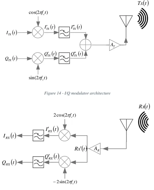
An alternative approach, to resolve this problem, is based on the I/Q modulation use. In Figure 14 and in Figure 15 are given the blocks diagrams of the two main macro-elements to this system realization, so a I/Q modulator and demodulator.
) 2 cos( fct ) 2 sin( fct t ITX t QTX T A t ITX ITX t t QTX QTX t
t TxFigure 14 - I/Q modulator architecture
) 2 cos( 2 fct ) 2 sin( 2 fct R A
t IRX
t QRX
t Rx
t IRX
t QRX
t x R Figure 15 - I/Q demodulator architecture
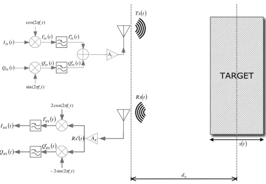
Support Theory 31 ) 2 cos(fct ) 2 sin(fct t ITX t QTX T A t ITX ITX t t QTX QTX t t Tx 0 d t x ) 2 cos( 2 fct ) 2 sin( 2 fct R A t IRX t QRX t Rx t IRX t QRX t x R
Figure 16 - Typical scenery for the vibrations monitoring applications through a CW radar Doppler.
As in the case previous case, it is possible to define the function that describes the distance from the radar to the target varying the time as shown in the eq. (45) and starting from this, can be obtained the ‘Round Trip’ time (eq. (46)).
𝑥̅(𝑡) = 𝑑0+ 𝑥(𝑡) (45) 𝜏(𝑡) =2𝑥̅(𝑡) 𝑐 = 2𝑑0 𝑐 + 2𝑥(𝑡) 𝑐 (46)
To understand in the detail how this radar type operates, it is necessary to analytically formulate the particular problem. The first operation phase is, of course, the signals generation. Particularly, for this architecture, it is necessary to produce in phase component (I) and in quadrature component (Q) to be transferred to the I/Q modulator as shown above in the Figure 14. Since it is desired to transmit a CW monochrome signal, it is necessary to fix at the I/Q modulator component to the expressions described in the eqs. (47)-(48),
𝐼𝑇𝑋(𝑡) = cos[2𝜋𝑓IF𝑡 + 𝜃IF(𝑡)] (47)
𝑄𝑇𝑋(𝑡) = sin[2𝜋𝑓IF𝑡 + 𝜃IF(𝑡)] (48)
where 𝑓𝐼𝐹 named intermediary frequency and 𝜃𝐼𝐹(𝑡) is the signal generator phase noise. The two signal components, applied to different modulator branches, suffer, in sequence, the mixing and filtering operations, that move their spectrum from the 𝑓𝐼𝐹 intermediate frequency modulator to the (𝑓𝑐− 𝑓𝐼𝐹) carrying frequency. This
Support Theory
32
operations sequence, shown in Figure 14 and known as 'UP-CONVERSION', is described in detail from the eq. (49) to the eq. (53).
𝐼𝑇𝑋′ (𝑡) = cos[2𝜋𝑓 𝑐𝑡 + 𝜃𝑐(𝑡)] ⋅ 𝐼𝑇𝑋(𝑡) = = cos[2𝜋𝑓𝑐𝑡 + 𝜃𝑐(𝑡)] cos[2𝜋𝑓𝐼𝐹𝑡 + 𝜃𝐼𝐹(𝑡)] = =1 2{cos[2𝜋(𝑓𝑐+ 𝑓𝐼𝐹)𝑡 + 𝜃𝑐(𝑡) + 𝜃𝐼𝐹(𝑡)] + cos[2𝜋(𝑓𝑐− 𝑓𝐼𝐹)𝑡 + 𝜃𝑐(𝑡) − 𝜃𝐼𝐹(𝑡)]} (49) 𝑄𝑇𝑋′ (𝑡) = sin[2𝜋𝑓 𝑐𝑡 + 𝜃𝑐(𝑡)] ⋅ 𝑄𝑇𝑋(𝑡) = = sin[2𝜋𝑓𝑐𝑡 + 𝜃𝑐(𝑡)] sin[2𝜋𝑓𝐼𝐹𝑡 + 𝜃𝐼𝐹(𝑡)] = =1 2{cos[2𝜋(𝑓𝑐− 𝑓𝐼𝐹)𝑡 + 𝜃𝑐(𝑡) − 𝜃𝐼𝐹(𝑡)] − cos[2𝜋(𝑓𝑐+ 𝑓𝐼𝐹)𝑡 + 𝜃𝑐(𝑡) + 𝜃𝐼𝐹(𝑡)]} (50)
After the low pass filter:
𝐼𝑇𝑋′′ (𝑡) =1 2cos[2𝜋(𝑓𝑐− 𝑓𝐼𝐹)𝑡 + 𝜃𝑇𝑋(𝑡)] (51) 𝑄𝑇𝑋′′ (𝑡) =1 2cos[2𝜋(𝑓𝑐− 𝑓𝐼𝐹)𝑡 + 𝜃𝑇𝑋(𝑡)] (52) where 𝜃𝑇𝑋(𝑡) = 𝜃𝑐(𝑡) − 𝜃𝐼𝐹(𝑡) (53)
represents the transmitter phase noise, with 𝜃𝑐(𝑡) that describes the local oscillator phase noise at 𝑓𝑐 frequency.
Before being transmitted, the two signal components, are added and the result is amplified and transferred to ether through an antenna use. This operation result is described by the eq. (54),
𝑇𝑥(𝑡) = 𝐴𝑇[𝐼𝑇𝑋′′ (𝑡) + 𝑄
𝑇𝑋′′ (𝑡)] = 𝐴𝑇cos[2𝜋(𝑓𝑐− 𝑓𝐼𝐹)𝑡 + 𝜃𝑇𝑋(𝑡)] (54)
where is the 𝐴𝑇 transmission gain.
The received signal, shown in the eq. (55), exhibits the same transmitted signal form, in comparison to which it results however delayed of 𝜏(𝑡), due to the propagation delay, (eq. (46)) and attenuated by 𝐿 factor, due to the target ‘Radar Cross-Section’ and to propagation losses.
Support Theory
33
𝑅𝑥(𝑡) = 𝐿 ⋅ 𝑇𝑥(𝑡 − 𝜏(𝑡)) (55)
Replacing the eqs. (46) and (54) inside the eq. (55), as shown in the eq. (56), the received signal, after the amplification stadium present in the receiver, is showing as in the eq. (57), where 𝐴𝑅 is the receiver gain.
𝑅𝑥(𝑡) = 𝐿 𝐴𝑇cos[2𝜋(𝑓𝑐− 𝑓𝐼𝐹)(𝑡 − 𝜏(𝑡)) + 𝜃𝑇𝑋(𝑡 − 𝜏(𝑡))] = = 𝐿 𝐴𝑇cos [2𝜋(𝑓𝑐− 𝑓𝐼𝐹)𝑡 − 4𝜋(𝑓𝑐− 𝑓𝐼𝐹)𝑑0 𝑐 − 4𝜋(𝑓𝑐− 𝑓𝐼𝐹)𝑥(𝑡) 𝑐 + 𝜃𝑇𝑋(𝑡 −2𝑑0 𝑐 )] (56) 𝑅𝑥′(𝑡) = = 𝐴𝑅 𝐿 𝐴𝑇cos [2𝜋(𝑓𝑐− 𝑓𝐼𝐹)𝑡 −4𝜋(𝑓𝑐− 𝑓𝐼𝐹)𝑑0 𝑐 − 4𝜋(𝑓𝑐− 𝑓𝐼𝐹)𝑥(𝑡) 𝑐 + 𝜃𝑇𝑋(𝑡 −2𝑑0 𝑐 )] (57)
Defining 𝐴 as shown in the eq. (58), it is possible reformulate the eq. (57) as shown in the eq. (59).
𝐴 = 𝐴𝑅⋅ 𝐿 ⋅ 𝐴𝑇 (58) 𝑅𝑥′(𝑡) = = 𝐴 cos [2𝜋(𝑓𝑐− 𝑓𝐼𝐹)𝑡 − 4𝜋(𝑓𝑐− 𝑓𝐼𝐹)𝑑0 𝑐 − 4𝜋(𝑓𝑐− 𝑓𝐼𝐹)𝑥(𝑡) 𝑐 + 𝜃𝑇𝑋(𝑡 −2𝑑0 𝑐 )] (59)
At this point, as shown in Figure 15, the received signal is divided and parallelly assigned as input to the two demodulator branches for the I/Q components extraction. The spectrum of the two signal components, through mixing and filtering operations, is once again moved from (𝑓𝑐 − 𝑓𝐼𝐹) carrying frequency to the
𝑓𝐼𝐹 intermediate frequency. This operations sequence, shown in Figure 15 and known as 'DOWN-CONVERSION', it is described in detail from the eq. (60) to the eq. (63).
Support Theory 34 𝐼𝑅𝑋′ (𝑡) = 𝑅𝑥′(𝑡)2 cos[2𝜋𝑓 𝑐𝑡 + 𝜃𝑐(𝑡)] = = 𝐴 cos [2𝜋(𝑓𝑐− 𝑓𝐼𝐹)𝑡 −4𝜋(𝑓𝑐− 𝑓𝐼𝐹)𝑑0 𝑐 − 4𝜋(𝑓𝑐− 𝑓𝐼𝐹)𝑥(𝑡) 𝑐 + 𝜃𝑇𝑋(𝑡 −2𝑑0 𝑐 ) + 2𝜋𝑓𝑐𝑡 + 𝜃𝑐(𝑡)] + 𝐴 cos [2𝜋(𝑓𝑐− 𝑓𝐼𝐹)𝑡 − 4𝜋(𝑓𝑐− 𝑓𝐼𝐹)𝑑0 𝑐 − 4𝜋(𝑓𝑐− 𝑓𝐼𝐹)𝑥(𝑡) 𝑐 + 𝜃𝑇𝑋(𝑡 −2𝑑0 𝑐 ) − 2𝜋𝑓𝑐𝑡 − 𝜃𝑐(𝑡)] = = 𝐴 cos [2𝜋(2𝑓𝑐− 𝑓𝐼𝐹)𝑡 − 4𝜋(𝑓𝑐− 𝑓𝐼𝐹)𝑑0 𝑐 − 4𝜋(𝑓𝑐− 𝑓𝐼𝐹)𝑥(𝑡) 𝑐 + 𝜃𝑇𝑋(𝑡 − 2𝑑0 𝑐 ) + 𝜃𝑐(𝑡)] + 𝐴 cos [−2𝜋𝑓𝐼𝐹𝑡 − 4𝜋(𝑓𝑐− 𝑓𝐼𝐹)𝑑0 𝑐 − 4𝜋(𝑓𝑐− 𝑓𝐼𝐹)𝑥(𝑡) 𝑐 + 𝜃𝑇𝑋(𝑡 − 2𝑑0 𝑐 ) − 𝜃𝑐(𝑡)] (60) 𝑄𝑅𝑋′ (𝑡) = 𝑅𝑥′(𝑡) 2 sin[2𝜋𝑓 𝑐𝑡 + 𝜃𝑐(𝑡)] = = 𝐴 sin [2𝜋(𝑓𝑐− 𝑓𝐼𝐹)𝑡 −4𝜋(𝑓𝑐− 𝑓𝐼𝐹)𝑑0 𝑐 − 4𝜋(𝑓𝑐− 𝑓𝐼𝐹)𝑥(𝑡) 𝑐 + 𝜃𝑇𝑋(𝑡 −2𝑑0 𝑐 ) + 2𝜋𝑓𝑐𝑡 + 𝜃𝑐(𝑡)] + 𝐴 sin [2𝜋(𝑓𝑐− 𝑓𝐼𝐹)𝑡 −4𝜋(𝑓𝑐− 𝑓𝐼𝐹)𝑑0 𝑐 − 4𝜋(𝑓𝑐− 𝑓𝐼𝐹)𝑥(𝑡) 𝑐 + 𝜃𝑇𝑋(𝑡 − 2𝑑0 𝑐 ) − 2𝜋𝑓𝑐𝑡 − 𝜃𝑐(𝑡)] = = 𝐴 sin [2𝜋(2𝑓𝑐− 𝑓𝐼𝐹)𝑡 − 4𝜋(𝑓𝑐− 𝑓𝐼𝐹)𝑑0 𝑐 − 4𝜋(𝑓𝑐− 𝑓𝐼𝐹)𝑥(𝑡) 𝑐 + 𝜃𝑇𝑋(𝑡 − 2𝑑0 𝑐 ) + 𝜃𝑐(𝑡)] + 𝐴 sin [−2𝜋𝑓𝐼𝐹𝑡 − 4𝜋(𝑓𝑐− 𝑓𝐼𝐹)𝑑0 𝑐 − 4𝜋(𝑓𝑐− 𝑓𝐼𝐹)𝑥(𝑡) 𝑐 + 𝜃𝑇𝑋(𝑡 − 2𝑑0 𝑐 ) − 𝜃𝑐(𝑡)] (61)
Support Theory 35 𝐼𝑅𝑋(𝑡) = = 𝐴 cos [−2𝜋𝑓𝐼𝐹𝑡 −4𝜋(𝑓𝑐− 𝑓𝐼𝐹)𝑑0 𝑐 − 4𝜋(𝑓𝑐− 𝑓𝐼𝐹)𝑥(𝑡) 𝑐 + 𝜃𝑇𝑋(𝑡 −2𝑑0 𝑐 ) − 𝜃𝑐(𝑡)] (62) 𝑄𝑅𝑋(𝑡) = = 𝐴 sin [−2𝜋𝑓𝐼𝐹𝑡 −4𝜋(𝑓𝑐− 𝑓𝐼𝐹)𝑑0 𝑐 − 4𝜋(𝑓𝑐− 𝑓𝐼𝐹)𝑥(𝑡) 𝑐 + 𝜃𝑇𝑋(𝑡 −2𝑑0 𝑐 ) − 𝜃𝑐(𝑡)] (63)
It is possible reformulate these expressions, in compact form, as shown in the eqs. (64) and (65) 𝐼𝑅𝑋(𝑡) = 𝐴 cos [−𝛼 − 𝛽 − 𝛾 + 𝜃𝑇𝑋(𝑡 − 2𝑑0 𝑐 ) − 𝜃𝑐(𝑡)] (64) 𝑄𝑅𝑋(𝑡) = 𝐴 sin [−𝛼 − 𝛽 − 𝛾 + 𝜃𝑇𝑋(𝑡 − 2𝑑0 𝑐 ) − 𝜃𝑐(𝑡)] (65)
effecting the substitutions indicated in the eqs. (66)-(68).
𝛼 = 2𝜋𝑓𝐼𝐹𝑡 (66)
𝛽 =4𝜋(𝑓𝑐− 𝑓𝐼𝐹)𝑑0
𝑐 (67)
𝛾 =4𝜋(𝑓𝑐− 𝑓𝐼𝐹)𝑥(𝑡)
𝑐 (68)
Using the equation (66) is possible reformulate the eqs. (47) and (48) as shown following.
𝐼𝑇𝑋(𝑡) = cos[𝛼 + 𝜃𝐼𝐹(𝑡)] (69)
𝑄𝑇𝑋(𝑡) = sin[𝛼 + 𝜃𝐼𝐹(𝑡)] (70)
Through the transmitted (eqs. (69) and (70)) and received (Equations (64) and (65)) I/Q component elaboration, according to the scheme shown in Figure 17, it is possible to extract the signal received phase containing the information on the monitored target motion.
![Figure 3 - Transmitted and received signal, and beat frequency individualized by a FMCW radar for a static target (courtesy of [47])](https://thumb-eu.123doks.com/thumbv2/123dokorg/2869299.9262/17.892.231.725.119.461/figure-transmitted-received-signal-frequency-individualized-static-courtesy.webp)
![Figure 4 - Transmitted and received signal, and beat frequency individualized by a FMCW radar for a moving target (courtesy of [47])](https://thumb-eu.123doks.com/thumbv2/123dokorg/2869299.9262/18.892.226.705.114.529/figure-transmitted-received-signal-frequency-individualized-moving-courtesy.webp)