ScienceDirect
Available online at Available online at www.sciencedirect.comwww.sciencedirect.com
ScienceDirect
Structural Integrity Procedia 00 (2016) 000–000
www.elsevier.com/locate/procedia
2452-3216 © 2016 The Authors. Published by Elsevier B.V.
Peer-review under responsibility of the Scientific Committee of PCF 2016.
XV Portuguese Conference on Fracture, PCF 2016, 10-12 February 2016, Paço de Arcos, Portugal
Thermo-mechanical modeling of a high pressure turbine blade of an
airplane gas turbine engine
P. Brandão
a, V. Infante
b, A.M. Deus
c*
aDepartment of Mechanical Engineering, Instituto Superior Técnico, Universidade de Lisboa, Av. Rovisco Pais, 1, 1049-001 Lisboa,
Portugal
bIDMEC, Department of Mechanical Engineering, Instituto Superior Técnico, Universidade de Lisboa, Av. Rovisco Pais, 1, 1049-001 Lisboa,
Portugal
cCeFEMA, Department of Mechanical Engineering, Instituto Superior Técnico, Universidade de Lisboa, Av. Rovisco Pais, 1, 1049-001 Lisboa,
Portugal
Abstract
During their operation, modern aircraft engine components are subjected to increasingly demanding operating conditions, especially the high pressure turbine (HPT) blades. Such conditions cause these parts to undergo different types of time-dependent degradation, one of which is creep. A model using the finite element method (FEM) was developed, in order to be able to predict the creep behaviour of HPT blades. Flight data records (FDR) for a specific aircraft, provided by a commercial aviation company, were used to obtain thermal and mechanical data for three different flight cycles. In order to create the 3D model needed for the FEM analysis, a HPT blade scrap was scanned, and its chemical composition and material properties were obtained. The data that was gathered was fed into the FEM model and different simulations were run, first with a simplified 3D rectangular block shape, in order to better establish the model, and then with the real 3D mesh obtained from the blade scrap. The overall expected behaviour in terms of displacement was observed, in particular at the trailing edge of the blade. Therefore such a model can be useful in the goal of predicting turbine blade life, given a set of FDR data.
© 2016 The Authors. Published by Elsevier B.V.
Peer-review under responsibility of the Scientific Committee of PCF 2016.
Keywords: High Pressure Turbine Blade; Creep; Finite Element Method; 3D Model; Simulation.
* Corresponding author. Tel.: +351 218419991. E-mail address: [email protected]
Procedia Structural Integrity 12 (2018) 317–329
2452-3216 2018 The Authors. Published by Elsevier B.V.
This is an open access article under the CC BY-NC-ND license (http://creativecommons.org/licenses/by-nc-nd/3.0/)
Peer-review under responsibility of the Scientific Committee of AIAS 2018 International Conference on Stress Analysis. 10.1016/j.prostr.2018.11.084
Available online at www.sciencedirect.com
ScienceDirect
Structural Integrity Procedia 00 (2018) 000–000
www.elsevier.com/locate/procedia
2452-3216 © 2018 The Authors. Published by Elsevier B.V.
This is an open access article under the CC BY-NC-ND license (http://creativecommons.org/licenses/by-nc-nd/3.0/) Peer-review under responsibility of the Scientific Committee of AIAS 2018 International Conference on Stress Analysis.
AIAS 2018 International Conference on Stress Analysis
Green sandwich structures under impact: experimental vs numerical
analysis
Simonetta Boria
a,*, Elena Raponi
a, Fabrizio Sarasini
b, Jacopo Tirillò
b, Luca Lampani
c aSchool of Science and Technology, University of Camerino, Camerino 62032, ItalybDepartment of Chemical Engineering Materials Environment, Sapienza-Università di Roma, Roma 00185, Italy cDepartment of Mechanical and Aerospace Engineering, Sapienza-Università di Roma, Roma 00185, Italy
Abstract
Nowadays, there is a growing interest for the use and development of materials synthesized from renewable sources in the polymer composites manufacturing industry; this applies for both matrix and reinforcement components. In the present research, flax fibers embedded in an epoxy resin have been proposed as an environmentally friendly alternative to traditional synthetic composites. In addition, this material system has been combined with agglomerated cork as core material for the fabrication of sandwich structures. The objective of this article is to analyze the suitability of using such green sandwich structures in applications where energy absorption due to low velocity impacts can be of importance.
Therefore green sandwich specimens with flax/epoxy face sheets and agglomerated cork as core have been manufactured and subjected to low velocity impacts at different energies. After the mechanical characterization of both skin and core material, a numerical model has been implemented through the non-linear dynamic code LS-DYNA. The FE analysis has been able to reproduce with a good level of accuracy the deformation mechanisms and the load-displacement diagrams for each energy level. © 2018 The Authors. Published by Elsevier B.V.
This is an open access article under the CC BY-NC-ND license (http://creativecommons.org/licenses/by-nc-nd/3.0/) Peer-review under responsibility of the Scientific Committee of AIAS 2018 International Conference on Stress Analysis.
Keywords: green composites; natural fibers; cork agglomerated; sandwich structure; impact behaviour
* Corresponding author. Tel.: +39-0737402503. E-mail address: [email protected]
10.1016/j.prostr.2018.11.084 2452-3216
© 2018 The Authors. Published by Elsevier B.V.
This is an open access article under the CC BY-NC-ND license (http://creativecommons.org/licenses/by-nc-nd/3.0/) Peer-review under responsibility of the Scientific Committee of AIAS 2018 International Conference on Stress Analysis.
ScienceDirect
Structural Integrity Procedia 00 (2018) 000–000
www.elsevier.com/locate/procedia
2452-3216 © 2018 The Authors. Published by Elsevier B.V.
This is an open access article under the CC BY-NC-ND license (http://creativecommons.org/licenses/by-nc-nd/3.0/) Peer-review under responsibility of the Scientific Committee of AIAS 2018 International Conference on Stress Analysis.
AIAS 2018 International Conference on Stress Analysis
Green sandwich structures under impact: experimental vs numerical
analysis
Simonetta Boria
a,*, Elena Raponi
a, Fabrizio Sarasini
b, Jacopo Tirillò
b, Luca Lampani
caSchool of Science and Technology, University of Camerino, Camerino 62032, Italy
bDepartment of Chemical Engineering Materials Environment, Sapienza-Università di Roma, Roma 00185, Italy cDepartment of Mechanical and Aerospace Engineering, Sapienza-Università di Roma, Roma 00185, Italy
Abstract
Nowadays, there is a growing interest for the use and development of materials synthesized from renewable sources in the polymer composites manufacturing industry; this applies for both matrix and reinforcement components. In the present research, flax fibers embedded in an epoxy resin have been proposed as an environmentally friendly alternative to traditional synthetic composites. In addition, this material system has been combined with agglomerated cork as core material for the fabrication of sandwich structures. The objective of this article is to analyze the suitability of using such green sandwich structures in applications where energy absorption due to low velocity impacts can be of importance.
Therefore green sandwich specimens with flax/epoxy face sheets and agglomerated cork as core have been manufactured and subjected to low velocity impacts at different energies. After the mechanical characterization of both skin and core material, a numerical model has been implemented through the non-linear dynamic code LS-DYNA. The FE analysis has been able to reproduce with a good level of accuracy the deformation mechanisms and the load-displacement diagrams for each energy level. © 2018 The Authors. Published by Elsevier B.V.
This is an open access article under the CC BY-NC-ND license (http://creativecommons.org/licenses/by-nc-nd/3.0/) Peer-review under responsibility of the Scientific Committee of AIAS 2018 International Conference on Stress Analysis.
Keywords: green composites; natural fibers; cork agglomerated; sandwich structure; impact behaviour
* Corresponding author. Tel.: +39-0737402503. E-mail address: [email protected]
1. Introduction
The last decades have seen fiber reinforced polymer composites as favorite candidate materials in structural design driven by lightweight. Recently, a resurgent interest in more eco-friendly composite concept has been witnessed (Mancuso et al. (2015)). These efforts were due to the advent of various commercial natural fiber reinforcements and natural core materials. Among natural fibers extracted from plants, flax fibers represent the leading choice (Yan et al. (2014)), even if their intrinsic stiffness and strength are still significantly lower than traditional synthetic reinforcements. A possible approach to enhance the stiffness of a monolithic laminate is to assemble it in a sandwich structure, separating the laminate skins by a suitable core material (Carlsson et al. (2011)).
The energy absorption ability of cellular materials is a well-known feature that has been successfully exploited in a variety of applications, including packaging, personal protective equipment and cores for structural sandwiches. Despite their positive and attractive characteristics, the use of synthetic cellular materials has been significantly questioned over the last years due to increasing environmental consciousness. In particular, a stricter environmental legislation is triggering a resurgent interest toward materials and structures from renewable resources able to replace their synthetic counterparts (Pickering et. al (2015)). In this regard cork, obtained from the bark of Quercus suber L tree, is an excellent example of renewable and recyclable cellular material (Silva et al. (2005)), characterized by high dimensional recovery, good thermal and acoustic insulation properties, limited permeability to liquids and gases, chemical stability and durability (Silva et al. (2005), Pereira (1988)). The mechanical response of cork and of its nearly isotropic agglomerated form has been investigated in depth over the years, in particular under quasi-static uniaxial compressive loading, leading to the understanding of the fundamental mechanisms behind its global behaviour (Gibson et al. (1981), Jardin et al. (2015), Moreira et al. (2010), Anjos et al. (2014)), whilst the behaviour of cork when subjected to dynamic loadings has received attention only in the last years. Sanchez-Saez et al. (2015) reported on the effect of thickness (15-70 mm) on the energy-absorption capacity of agglomerated cork and found it not dependent on the thickness of specimen while an increment of the specimen thickness reduced the contact force for the same impact energy. Recently Ptak et al. (2017) analysed the dynamic crushing behaviour of agglomerated cork when subjected to impacts from 120 J up to 850 J, in an attempt to use this natural materials in a broader range of safety applications. The authors included in the study two different agglomerated corks, characterized by different density and grain size and one expanded (or black) cork. The two agglomerated corks from 120 J up to 250 J were able to withstand the impact energy and only few milliseconds were needed to recover most of the initial dimensions even if compressed up to 80%. At the highest energy levels (500 J and 850 J), different amounts of densification for both agglomerates were detected, along with the formation of cracks during impact. On the contrary, the expanded cork was not able to survive an impact energy higher than 250 J. Interestingly, the authors investigated also the effect of temperature, performing impacts at 50 °C but in most cases only small differences (maximum 10%) were identified and ascribed to the natural variability found in this renewable material. In literature, most of the studies dealing with the impact performance of agglomerated cork, have been carried out in crushing conditions, usually fully supporting the material during the impact event. An issue that has attracted scarce coverage in literature is instead the low velocity impact behaviour of agglomerated cork with boundary conditions similar to the ones widely used for assessing the impact performance of composite laminates. This is particularly important if agglomerated cork is to be used as a core in sandwich structures subjected to low velocity impacts (Castro et. al (2010), Hachemane et al. (2013)).
The present work investigates the response to low-velocity impacts of green sandwich panels made of flax and cork raw materials. In particular, the sandwich skin faces were made of a unidirectional flax fiber reinforced epoxy laminate and the core material was a high-density agglomerated cork panel, given by the mixture of natural cork and an organic binder as polyurethane. The experimental characterization was performed on the same sandwich type varying the impact energy level, both for the bare cork than for the sandwich structure. It is well known that the use of a numerical model reduces the manufacturing cost and time of composite material by providing its analysis before actual production. Hence, in such work, the analysis was conducted also from the numerical point of view, using the non-linear dynamic code LS-DYNA. The comparison with the experimental results shows a good level of accuracy of the discrete model.
2. Materials and methods
2.1. Materials and fabrication of sandwich structures
The green sandwich structure investigated in this experimental work is characterized by flax/epoxy face sheets and agglomerated cork as core material. For the skins, a unidirectional prepreg material system (FLAXPREG UD 180) based on epoxy matrix with a fibre areal weight of 180 g/m2 supplied by Lineo was used. Two face sheets were used to encapsulate an agglomerated cork (commercially labelled as CR-12J) supplied by CORKSRIBAS, which is characterized by a density of 240-315 kg/m3 and a grain size = 1-2 m. The agglomerated cork was provided with a thickness of 30 mm. The face sheets were manufactured with a quasi-isotropic configuration [+60/0/-60]s and the panels were vacuum-bagged and fully cured under pressure in an autoclave to the manufacturer's specifications up to a fibre volume fraction of 0.50±0.04. The flax fibre laminates with a thickness of 1.4 mm and the core were cut to required dimensions (10 × 10 cm) and Redux 609 by Hexcel, an epoxy film adhesive containing a cotton scrim, was used to bond the face sheets to the core. Sandwich structures were vacuum-bagged and fully cured without additional pressure in an autoclave to the epoxy film manufacturer's specifications.
2.2. Quasi-static characterization techniques
Flax/epoxy face sheets were tested for flexural properties in accordance with ASTM D790 in a three-point bending configuration with a support span of 60 mm and a crosshead speed of 4 mm/min. At least three specimens were tested. Core material was characterized in static compression tests with at least five specimens (30 × 30 × 30 mm) at a velocity of 10 mm/min. All the quasi-static tests were carried out using a Zwick/Roell Z010 testing machine.
2.3. Dynamic characterization technique
Bare core material and the whole sandwich structures were subjected to low velocity impact tests using an instrumented drop-weight impact testing machine (CEAST/Instron 9340). The hemispherical impactor had a diameter of 20 mm and tests were performed at different energy levels, namely 5, 10, 15, 20, 25 and 30 J. The additional weights were changed each time to keep constant the impact speed at 1.83 m/s (0, 3, 6, 9, 12 and 15 kg respectively). The specimens were pneumatically clamped between two steel plates leaving a circular unsupported area with a diameter of 40 mm.
2.4. Microstructural investigation
The morphology and microstructure of core material and face-sheets were examined by scanning electron microscopy (SEM) (Philips XL 40). The specimens were sputter coated with gold prior to investigation.
3. Results and discussion
3.1. Morphological image analysis and quasi-static mechanical properties of single constituents
Fig. 1 shows the morphology and structure of agglomerated cork used in the present study. The typical cellular microstructure was found, with a relatively small cell size and cell wall thickness, being in the range 25-30 μm and 0.3-0.6 μm, respectively.
Fig. 1. SEM micrographs of agglomerated cork CR12-J at different magnifications.
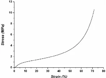
The typical stress–strain curve obtained from compression test on cork is reported in Fig. 2. It is characterized by three common stages, namely a linear elasticity at low stresses due to cell wall bending, a long collapse plateau due to elastic buckling of cell walls and finally a densification stage where the collapse of cells and compaction of the successive cell walls take place (Fernandes et al. (2014)). From the curve in Fig. 2, the compressive modulus (calculated as the average slope of the stress–strain curve in the elastic stage) and the collapse stress (calculated as the intersection of the lines fitting the plateau and the elastic stages) were obtained and reported in Table 1. It is worth mentioning that the stress was found to be not constant during the collapse propagation in agglomerated cork, which is likely due to structural heterogeneities.
Fig. 2. Representative compression stress–strain curve for agglomerated cork. Table 1. Mechanical properties of agglomerated cork in compression.
Modulus (MPa) Strength (MPa)
The flexural properties of flax/epoxy face sheets, already investigated in a previous work (Sarasini et al. (2018)), are summarized in Table 2 for the sake of completeness. As already observed in (Sarasini et al. (2018)), from the curve (Fig. 3) obtained using a Zwick/Roell displacement transducer, it is possible to note a marked nonlinear response that can be ascribed to the nonlinear deformation of flax fibres and to the occurrence of kink bands in the fibres, causing local stress concentrations (Anderson et al. (2015), Baley (2002)). The mechanical properties of these facesheets can be definitely improved as regards the fibre/matrix interface, as confirmed by the fracture surface analysis of composites (Fig. 4) that showed fibre pull-out even if no clear gaps between fibre and matrix can be found and, on the contrary, fibre fibrillation can be easily noted.
Table 2. Summary of mechanical properties for flax/epoxy face sheets.
Flexural modulus (MPa) Flexural strength (MPa) Flax/epoxy facesheet 7.20 ± 0.26 91.95 ± 2.79
Fig. 3. Typical flexural stress-strain curve for flax/epoxy facesheets.
3.2. Low-velocity impact behavior of the bare core
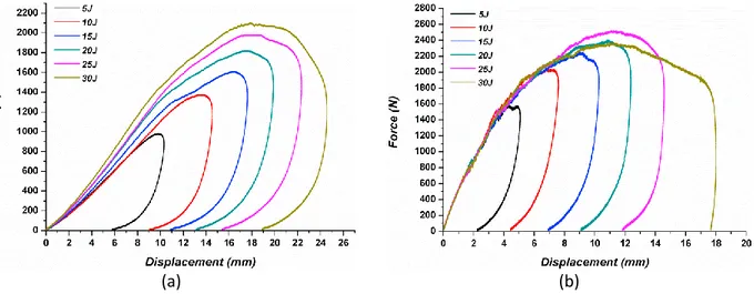
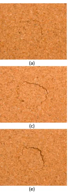
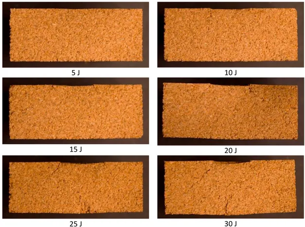
Fig. 5 shows the typical force vs. displacement curves for agglomerated cork at different impact energies. It can be stated that for CR12-J cork the penetration threshold was not reached in the range of impact energies tested, as confirmed by the rebounding of the impactor, which is represented by the closed curves shown in Fig. 5-a. Peak load was found to increase with increasing impact energy, while the curves are smooth without evidence of significant load drops that are usually associated with marked damage nucleation and growth. Cork specimens were found to absorb a huge amount of impact energy, delivering a damage degree (ratio between absorbed energy and impact energy) in the range 0.81 – 0.91 for impact energies from 5 J up to 30 J. The existence of a rebounding phase for cork specimens suggests less damage occurrence in the material. No damage in the back face was detected up to 15 J, being all concentrated on the impacted surface (Fig. 6). With increasing impact energy, in addition to indentation on the impacted surface, cracks appeared on the back face. This is confirmed also by the visual observation of cross sections through the impact point, as shown in Fig. 7. The damages were limited to the impacted surface in the form of local indentation with shear cracks propagating from the edges of the local dent and cracks on the bottom face (at 25-30 J) due to bending stresses which cause tensile failure in the transverse direction, because membrane effects can be predominant. In addition cork specimens exhibited cell wall collapse due to buckling with energy absorption at high strains that can be quite considerable with no signs of cell walls breakage, as already confirmed in (Sarasini et al. (2018)).
(a)
(b)
Fig. 5. Characteristic force versus displacement curves for (a) bare agglomerated cork and (b) sandwich structures.
3.3. Low-velocity impact behavior of the sandwich
Also for complete sandwich structures, the agglomerated cork enabled a rebounding stage over the whole impact energy range investigated (Fig. 5-b), even though in this case a 30J-impact caused severe damage in the sandwich structure, as the force was found to decrease compared to what happened with the other impact energies. The presence of a much more pronounced plateau on the force vs. displacement curves for the sandwiches is the evidence of several damage modes due to the presence of the skins. Facesheets were perforated through fracture of the flax fibres even at 10 J. A significant energy absorption was found for sandwich structures, with damage degree values in the range 0.78 – 0.97, thus suggesting that the energy absorbed by fracture of the top facesheet governs the energy absorption in low velocity impacts, as no damage on the back facesheet occurred (Fig. 8).
(a)
(b)
(c)
(d)
(e)
(f)
Fig. 6. Close-up views of the damage progression in the agglomerated cork impacted at: (a) 10 J (front face); (b) 15 J (front face); (c) 20 J (front face); (d) 20 J (back face); (e) 30 J (front face); (f) 30 J (back face).
Fig. 9 shows the influence of the skin on crack propagation modes into the cork CR-12J. In neat cork, three kinds of damages were observed: (i) the indentation made by the impactor which is always seen as a plateau of a certain depth; (ii) shear cracks can also be observed originating from the edges of the plateau and propagating at an angle of about 45°. These shear cracks are created by the high transverse shear stress (linked to the contact force and contact area) through the material. (iii) Finally, tensile cracks occurring in the non-impacted side of the sample and due to the sample global bending are generally present and usually occur after the other damage modes. In the sandwich core, only a transverse crack starting from the center of the impacted zone can be observed where facesheet fracture took place. Moreover from the characteristic force-displacement curves it is possible to observe the same stiffness value varying the energy levels (Fig. 5-b), contrary to the bare cork where there was a growing of the stiffness increasing the impact values (Fig. 5-a). This is due to the presence of the composite skins that tend to reduce the strain-rate dependency.
Fig. 7. Cross sectional views of bare cork impacted from 5 to 30 J.
Fig. 8. Comparison of damage evolution in the impacted surface of CR-12J/flax sandwich structures.
10 J
30 J
Fig. 9. Cross sectional views of sandwich structures based on agglomerated cork impacted at 10 J and 30 J.
5 J
10 J
15 J
20 J
4. Numerical model
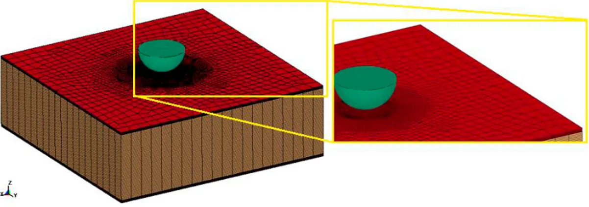
HyperMesh 2017 was used as pre-processor of the model to solve with LS-DYNA and LS-PrePost was used as post-processor to see results and animate them. The modelled composite sandwich plate consists of two external skins of flax/epoxy laminate (each skin consists of 6 unidirectional layers with specific fibers orientation, as mentioned before) and a cork core. Being the aim of the study to assess the energy absorption of the sandwich laminate, the good compromise between model detail/accuracy and simulation time was reached by a shell-brick-shell model. Therefore both the impactor and the inner core were meshed with eight node brick elements. A finer mesh was used in the impact region, also for the skins, to obtain more accurate results. The smaller element size in the impact zone is about 0.4 x 0.4 mm2. Among the simplified models available in LS-DYNA material library, MAT57 (MAT_LOW_DENSITY_FOAM) was adopted for the core, for which equivalent non-linear curves to define the constitutive equations under pure loads and specific parameters such as failure criteria, based on cut-off stress, and dumping must be defined for an accurate simulation. If it is necessary to reproduce also the elements deletion during crushing the MAT_ADD_EROSION must be defined on the core material. The material model of impactor was set as MAT20 (MAT_RIGID) and the solids were constrained in X, Y displacements and all rotations but free to move in Z direction (Fig. 10). The impactor velocity was always 1.83 m/s; only the impactor mass was changed during each simulation, in order to reach different energy levels.
Fig. 10. Geometry and mesh of sandwich plate.
It is well known that one of the main source of damage in laminated composite structures is delamination; therefore, a particular attention in modelling such aspect was placed. Laminated composite materials can be modelled in three different ways in LS-DYNA code (Dogana et al. (2012)). The first method is using thin shell elements with tiebreak contact for delamination. The second method is to employ multilayer thick shell (TSHELL) formulations by setting the number of integration points equal to the number of layers and angles of each layer. The delamination in the thick shell will be modelled by cohesive zone elements. The last method is to use solid layers with their material angle together with cohesive layers between the solid layers. Despite a 3D modelling for thick composite structures is preferable as the through thickness stress variation can be captured accurately, the use of solid elements is restricted because the size of the model becomes huge increasing dramatically the solution time.
In such analysis multi-shell approach with tiebreak contact was adopted. A tiebreak contact works as adhesive to bond the sub-laminates in the LS-DYNA model and initially it is active for nodes which are initially in contact. Normal and shear failure strength must be defined for tiebreak contact to check the bond failure. During the loading, the damage of the material is a linear function of the distance between the two points which are initially in contact. When the critical opening is reached, the contact will be broken and the sub-laminates are converted into two separate surfaces with regular surface to surface contact between them to prevent penetrations. Under tensile load, tiebreak allows the separation of the surfaces and ultimately the failure of the tied surfaces will occur under the following failure criterion:
2 2 1 n s NFLS SFLS
(1)where NFLS is tensile failure strength and SFLS is shear failure strength of the adhesive. An adhesive material with the properties of NFLS = 50 MPa and SFLS = 40 MPa was chosen, being typical properties for epoxy adhesives usually used in structural applications.
In order to capture the damage evolution during the impact of the external composite skins the MAT54 (MAT_ENHANCED_COMPOSITE _DAMAGE), which is based on Chang-Chang failure criterion (Chang et al. (1987), Choi et al. (1991)), was used. The Chang-Chang failure criteria for MAT54 can be summarized as follows: Tensile fiber failure mode:
aa>0 then 2 2 1 0 failed 0 elastic aa ab f t c e X S
(2) After failure Ea=Eb=Gab=ab=ba=0; Compressive fiber failure mode:aa<0 then 2 2 1 0 failed 0 elastic aa c c e X
(3) After failure Ea= ab=ba=0; Tensile matrix failure mode:bb>0 then 2 2 2 1 0 failed 0 elastic bb ab m t c e Y S
(4) After failure Eb=ba=0Gab=0; Compressive matrix mode:bb<0 then 2 2 2 2 1 1 0 failed 0 elastic 2bb 2c bb ab d c c c c Y e S S Y S (5) After failure Eb=ab=ba=0Gab=0;
where in Equations 1-4 the subscript “a” refers to fiber direction and “b” to transverse direction, normal to fiber. In the specific model failure can occur when one of the following condition is reached:
If the maximum strain for fiber tension (DFAILT) is zero, failure occurs in the tensile fiber model if the Chang-Chang failure criterion is satisfied.
If DFAILT is greater than zero, failure occurs if the tensile strain is greater than DFAILT or less than the maximum strain for fiber compression (DFAILC).
If the time step size criteria for element deletion (TFAIL) is greater than zero, failure occurs according to the element time step.
The element is deleted only when failure occurs in the entire composite layers (through thickness integration points). The attached elements to the deleted element become “crash-front” elements, whose strength can be reduced by a specific parameter, called SOFT, when TFAIL value is greater than zero (LS-DYNA manual (2006)).
Different contact definitions are needed between components in the model. CONTACT_AUTOMATIC_
SURFACE_TO_SURFACE was used between impactor and plates.
CONTACT_AUTOMATIC_ONE_WAY_SURFACE_TO_SURFACE_TIEBREAK and CONTACT_TIED_SHELL_EDGE_TO_SURFACE_BEAM_OFFSET were used between sub-laminates of the
composite plate and between skins and foam, respectively.
The boundary condition applied to the models had to replicate the clamping system used in experimental data. This means that the boundary condition used had to be circular, with a diameter matching that of the clamp, and fully fixed.
5. Comparison between numerical vs experimental results
5.1. Low-velocity impact behavior of the bare core: numerical vs experimental analysis
Initially only the impact of the bare core with the indenter was modelled. Also from the numerical point of view it can be observed that, despite the small internal damages, no significant loss of load was recorded, especially for the lower energy levels (Fig. 11).
The addition of the erosion criteria on the cork model permitted to reproduce also the internal damage of the core during crushing. From Fig. 12 it is evident how damage tended to manifest in the zone between the impact area and the clamping one, where the strain due to tensile stresses was greater.
Fig. 12. Maximum principal strain distribution in the cut section.
5.2. Low-velocity impact behavior of the sandwich: numerical vs experimental analysis
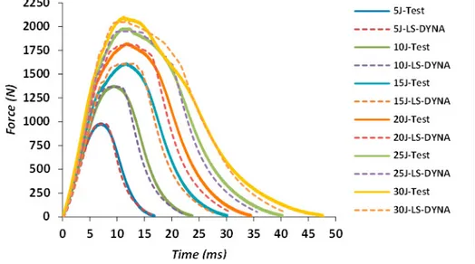
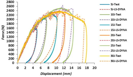
The addition of external skins to the previous model has permitted to model the complete sandwich structure. As mentioned before, particular attention must be placed to the damage mechanisms of the composite layers because mainly them are responsible for the load drops. The Fig. 13 shows the comparison between experimental and numerical data in terms of load versus displacement. Despite the complexity of the model and the simplification adopted, the discrete model was able to capture the main crushing phenomena. The presence of peaks and valleys are due to the elements deletion for the failure criteria implemented. Such aspect, less evident in the experimental data given the continuity of the structure, can be reduced using finer mesh size even though an increase in the simulation times must be expected.
6. Conclusions
An experimental campaign on a new composite sandwich structure with agglomerated cork as core and flax/epoxy laminates as face sheets under low velocity impacts at different energy levels has been conducted. The damage resistance has been investigated also numerically, through the implementation of a non-linear dynamic FE model solved with LS-DYNA. A flax-cork sandwich plate was modelled with a combination of shell elements (face sheets) and solid elements (core). The results showed that agglomerated cork can be a renewable alternative to traditional synthetic foam materials thanks to the typical collapse mechanism of cell able to contain extension of damage and absorb high amount of energy.
References
Mancuso, A, Pitarresi, G., Tumino, D., 2015. Mechanical behaviour of a green sandwich made of flax reinforced polymer facings and cork core. Procedia Engineering 109, 144-153.
Yan, L., Chouw, N., Jayaraman, K., 2014. Flax fibre and its composites-A review. Composites Part B: Engineering 56, 296-317.
Carlsson, L.A., Kardomateas, G.A., 2011. Structural and failure mechanics of sandwich composites, in “Solid Mechanics and its Applications”, In: Carlsson, L.A., Kardomateas, G.A. (Ed.). Springer Science, 121.
Pickering, K.L., Aruan Efendy, M.G., Le, T.M., 2016. A review of recent developments in natural fibre composites and their mechanical performance. Composites Part A: Applied Science and Manufacturing 83, 98-112.
Silva, S.P., Sabino, M.A., Fernandes, E.M., Correlo, V.M., Boesel, L.F., Reis, R.L., 2005. Cork: properties, capabilities and applications. Int ernational Materials Reviews 50, 345–365.
Pereira, H., 1988. Chemical composition and variability of cork from Quercus suber L. Wood Science and Technology 22, 211–218.
Gibson, L.J., Easterling, K.E., Ashby, M.F., 1981. The structure and mechanics of cork. Proceedings of the Royal Society of London. Series A, Mathematical, Physical and Engineering Sciences 377, 99-117.
Jardin, R.T., Fernandes, F.A.O., Pereira, A.B., Alves de Sousa, R.J., 2015. Static and dynamic mechanical response of different cork agglomerates. Materials and Design 68, 121–126.
Moreira, R.A.S., de Melo, F.J.Q., Dias Rodrigues, J.F., 2010. Static and dynamic characterization of composition cork for sandwich beam cores. Journal of Materials Science 45, 3350–3366.
Anjos, O., Rodrigues, C., Morais, J., Pereira, H., 2014. Effect of density on the compression behaviour of cork. Materials and Design 53, 1089– 1096.
Sanchez-Saez, S., García-Castillo, S.K., Barbero, E., Cirne, J., 2015. Dynamic crushing behaviour of agglomerated cork. Materials and Design 65, 743–748.
Ptak, M., Kaczynski, P., Fernandes, F.A.O., de Sousa, R.J.A., 2017. Assessing impact velocity and temperature effects on crashworthiness properties of cork material. International Journal of Impact Engineering 106, 238–248.
Castro, O., Silva, J.M., Devezas, T., Silva, A., Gil, L., 2010. Cork agglomerates as an ideal core material in lightweight structures. Materials and Design 31, 425–432.
Hachemane, B., Zitoune, R., Bezzazi, B., Bouvet, C., 2013. Sandwich composites impact and indentation behaviour study. Composites Part B: Engineering 51, 1–10.
Fernandes, F.A.O., Pascoal, R.J.S., Alves de Sousa, R.J., 2014. Modelling impact response of agglomerated cork. Materials and Design 58, 499– 507.
Sarasini, F., Tirillò, J., Lampani, L., Barbero, E., Sanchez-Saez, S., Valente, T., Gaudenzi, P., Scarponi, C., 2018. Impact behavior of sandwich structures made of flax/epoxy face sheets and agglomerated cork. Journal of Natural Fibers, 1-21.
Andersons, J., Modniks, J., Sparnins, E., 2015. Modeling the nonlinear deformation of flax-fiber-reinforced polymer matrix laminates in active loading. Journal of Reinforced Plastics and Composites 34, 248–256.
Baley, C., 2002. Analysis of the flax fibres tensile behaviour and analysis of the tensile stiffness increase. Composites: Part A 33, 939-948. Chang, F.K., Chang, K.Y., 1987. A progressive damage model for laminated composites containing stress concentrations. Journal of Composite
Materials 21, 834-855.
Choi, H.Y., Wu, H.Y.T., Chang, F.K., 1991. A new approach toward understanding damage mechanisms and mechanics of laminated composites due to low-velocity impact: Part II-Analysis. Journal of Composite Materials 25, 1012-1038.
LS-DYNA , 2012. Version 971 R6 Theory Manual. Livermore Software Technology Corporation, California.
Dogan, F., Hadavinia, H., Donchev, T., Bhonge, P.S., 2012. Delamination of impacted composite structures by cohesive zone interface elements and tiebreak contact. Central European Journal of Engineering 2, 612-626.