0
UNIVERSITA’ DEGLI STUDI DI PISA
Facoltà di Ingegneria
Corso di Laurea in Ingegneria Biomedica
Tesi di Laurea Magistrale
STUDY AND DEVELOPMENT OF
A SENSORIZED PLATFORM FOR THE MONITORING OF
LVAD-IMPLANTED PATIENTS
Relatori: Candidato: Prof.ssa Arianna Menciassi Maura Cuppone Dr.ssa Monica Vatteroni
24 Settembre 2013 Anno Accademico 2012-2013
1
2
T
ABLE OF CONTENTS
INTRODUCTION ... 4
CHAPTER 1 ... 6
1.1 An innovative approach for LVAD ... 6
1.2 Ventricular assist device ...10
1.2.1 Synergy™ Device ...15
1.3 Central Control Unit ...18
1.4 Monitoring sensors...23
1.5 Transcutaneous Energy Transfer System ...25
1.6 Telemetry ...29
1.7 Proposed implantable platform ...34
CHAPTER 2 ...36
2.1 The Auto-Regulation Unit ...36
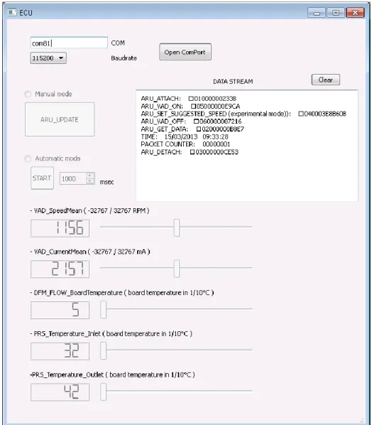
2.2 Pc-based graphical user interface: splitting of the HMI ...42
2.3 Implementation of an UART in VHDL code ...45
2.3.1 Universal Asynchronous Receiver/Transmitter ...45
2.3.2 UART implementation for ARU interactions ...46
2.4 Developing test software ...48
2.4.1 Python simulator for the ECU interface ...50
2.4.2 Python simulator for the ARU interface ...51
CHAPTER 3 ...54
3.1 Sensorized platform ...54
3.2 Pressure sensor replacement ...57
3.3 Signal conditioning for the pressure sensor ...59
3.3.1 Zero offset setting ...59
3.3.2 Characterization for the pressure sensor ...60
3.4 Human Machine Interface Upgrade ...64
CHAPTER 4 ...65
4.1 Transcutaneous Energy Transfer System ...65
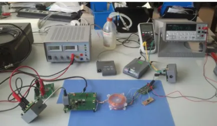
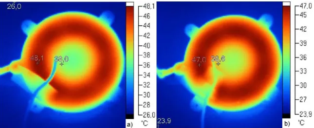
4.2 Coil temperature measurements ...70
4.1.1 Temperature monitoring of the ETET coil depending on the VAD load ...72
4.1.2 Temperature monitoring under vertical misalignment ...74
3
4.1.4 Temperature monitoring under angular misalignment ...77
4.3 ITET rectifier efficiency ...79
CHAPTER 5 ...83
5.1 Medical Implant Communication Service – Telemetry ...83
5.1.1 Implantable transceiver module ...84
5.2 Antenna measurements in tissue (ex-vivo and in-vitro) ...86
5.2.1 Measurements with implantable Dipole and Printed loop antenna ...86
5.2.2 Antenna Measurements in the German Aerospace Center (DLR) ...94
5.2.3 Dielectric enclosure influence ...96
5.2.4 Ex-vivo and in-vitro measurements ...97
CONCLUSIONS AND OUTLOOK ... 104
REFERENCES ... 107 APPENDIX A ... 109 APPENDIX B ... 111 APPENDIX C ... 113 APPENDIX D ... 115 APPENDIX E ... 120 APPENDIX F ... 122
4
INTRODUCTION
Diseases of the heart and circulatory system are the main cause of death in Europe, accounting for over 4 million deaths each year. In particular, heart failure by itself accounts for almost 1.1 million deaths each year and it is more common among old people, in fact approximately 6% to 10% of people older than 65 years are affected by this disease.
Heart failure is an abnormal health condition characterized by the inability of the heart to supply sufficient blood-borne nutrients for the body’s metabolic demands. It is caused by heart-related factors, above all myocardial infarction, cardiogenic shock and myocardial infection, but also valve deformity, progressive coronary artery diseases, congenital defects diseases or external factors, such as hypertension, increased cardiac demands or increased volume load.
The last chance for heart failure has been cardiac transplantation but the disparity between availability and demand of heart donors leads to the death of a significant number of patients while waiting for a new heart. In fact, the number of patients in the European Union who potentially could benefit from cardiac transplantation in 2011 was estimated to be about 4,000, whereas the number of patients dying on waiting lists was estimated to be 5,500.
As a consequence, the mechanical support is considered as a viable option by taking over the pumping functions of the natural heart. The principal requirements for such support systems are that the mechanical components must be necessarily small and operate without failing under highly stressful conditions.
Nowadays, different mechanical ventricular assist devices (VADs) are in use. A VAD is a mechanical circulatory device used to partially reduce the payload of a failing heart. The last generation of VAD system consists of a pump, partially performing the fluid actuation work, a control unit and a power supply.
VADs are currently used as a bridge to heart transplantation, working as a temporary support for patients awaiting for a new organ. More recently, a revolutionary approach has been proposed, which regards the possibility to recur to the device therapy also as destination therapy for patients who are not candidates for transplantation (like old
5 people or patients who show the ability to recover the cardiac functions thanks to the pump help).
In order to enhance the VADs applicability for a long-term therapy usage, current research is going towards VADs miniaturization, sensorization and development of more comfortable devices able to dynamically respond to the support needs, depending on the subject activity.
A control system for continuous-flow LVAD able to automatically respond to physiologic cardiac demands is required. The current methodology makes use of pumps that operate at a fixed speed set according to the patient's activity level. This control is carried out by the physician, by setting the desired flow. Then, a VAD controller can have the capability to automatically adjusts the current and voltage applied to the pump to achieve and maintain the desired flow. Thus, it is clear that a continuous remote automatic monitoring system could guarantee much more consistency and safety. Especially to reach the goal of a long-term therapy, which needs at least the reduction of patient dependence on clinical management allowing her/him to return home, the development and integration of an automatic, robust and adaptive physiological control strategy is mandatory. The system should be able for fast response to physiologic cardiac demand by an automatic feedback mechanism which is directly based upon physiologic indicators of cardiac demand.
An innovative system for the implementation of all these features could be an integrated platform which aims for helping the physician to easily monitor the VAD and for giving a better life quality to the patient.
This intelligent platform is at the basis of this thesis and its components and their behavior are described in the following chapters.
6
CHAPTER
1
1.1
A
N INNOVATIVE APPROACH FORLVAD
Heart failure and related pathologies are the most frequent cause of death in the industrialized countries. The ageing of the world population and the low availability of heart donors with respect to the demand have led to the develop and experimentation of device therapy for patients with heart failure, not only as bridge to transplant, but also as destination therapy.
Heart failure (HF), also known as a cardiac or myocardial failure, is an abnormal health condition characterized by the inability of the heart to supply sufficient blood-borne nutrients for the body’s metabolic demands. End-stage HF is the leading cause of mortality, morbidity and disability worldwide.
In fact, diseases of the heart and circulatory system (cardiovascular disease or CVD) are the main cause of death in Europe, accounting for over 4 million deaths each year. Nearly half (47%) of all deaths are from CVD (52% of deaths in women and 42% of deaths in men). The main forms of CVD are coronary heart disease (CHD) and HF. HF by itself accounts for almost 1.1 million deaths in Europe each year. More than one over seven women (15%) and one over ten men (10%) die from the disease.
The annual rate of hospital discharges for CVD in Europe in 2008 and 2009 was just under 2,500 per 100,000 population. HF, in particular, is estimated to cost the EU economy over €38 billion a year: around one-fifth of the overall cost of CVD.
Reported case fatality rates in 21 European countries show also more than three-fold differences in acute myocardial infarction case fatality rates, from 2.3% in Denmark to 8.6% in Belgium.
In developed European countries, 17% of all DALYs (Disability Adjusted Life Year) lost were due to CVD, making it the second largest single cause after neuropsychiatric disorders [1].
Furthermore, HF is more common among old people, in fact approximately 6% to 10% of people older than 65 years have HF, and approximately 80% of patients hospitalized with HF are more than 65 years old [2].
7 HF is caused by both heart-related factors, above all myocardial infarction, cardiogenic shock and myocardial infection but also valve deformity, progressive coronary artery diseases, congenital defects diseases or external factors, such as hypertension, increased cardiac demands or increased volume load.
The myocardial infarction, often called heart attack, is predominantly a condition of the left ventricle and occurs when the blood flow through one or more of the coronary arteries is obstructed. Leaving the area of the myocardium previously fed by the occluded coronary artery without oxygen, the result is the necrosis, or tissue death, of the heart involved area. After a myocardial infarction, the ability of the heart to function as a mechanical pump is directly related to the extent of the myocardial damage.
Cardiogenic shock is characterized by a decreased pumping ability of the native heart, causing a shock like state characterized by inadequate tissues perfusion. It usually occurs in conjunction with, or as a direct result of, ischemic damage to the heart muscle and is most often initiated by an acute myocardial infarction. The damaged heart muscle loses its contractility, reducing, on a mechanical level, the ejection fraction and cardiac output.
Finally, the latest of the main HF cause is the myocardial infection. This is usually the result of acute myocarditis, or infection of the heart muscle. Infection may also affect the endocardium, native or prosthetic valves, or the cardiac conduction system [3]. The last chance for HF has been cardiac transplantation, since Barnard successfully transplanted a human heart for the first time in 1967. But the disparity between availability and demand of heart donors leads to the death of a significant number of patients while waiting for a new heart. In fact, the number of patients in the European Union who potentially could benefit from cardiac transplantation in 2011 was estimated to be about 4,000, whereas the number of patients dying on waiting lists was estimated to be 5,500 [4]. As a result, the mechanical support results as a viable option: it has to take over the pumping functions of the natural heart and the principal requirements are that the mechanical components are necessarily small and must operate without failing under highly stressful conditions.
Nowadays different mechanical ventricular assist devices (VADs) are in use. A VAD is a mechanical circulatory device used to partially reduce the payload of a failing heart. It is different from an artificial heart, which is designed to completely replace cardiac function and generally require the removal of the patient's heart.
8 VADs are currently used as a bridge to heart transplantation, working as a temporary support for patients awaiting a new organ or, more recently, as destination therapy for patients who are not candidates for transplantation. It was observed that VADs could double survival at 1 year from implant and triple survival at 2 years [6].
Experiments and clinical experiences show that, if the heart is chronically unloaded, there is the possibility to recover the cardiac functions to the extent that the patient could be weaned from the device and a transplantation could be avoided. According to the clinical experience, the incidence of recovery, allowing left VAD (LVAD) explantation in patients affected by chronic cardiomyopathy, ranges from 18 to 72% [2]. But heart recovery mechanisms and related time are still unknown since today VADs are mainly implanted on patients in heart failure end stage with multiorgan failure. However, it has been observed in some of these patients a dramatic reduction of left ventricular size during unloading with a LVAD with improvement or even restoration of cardiac function. It is worth mentioning that it is necessary to study heart recovery even in younger patients in which LVAD would allow good functional recovery, but with low probability to be transplanted and high probability for the need of long term assistance.
In order to enhance the VADs applicability and to improve patient life quality, current research is going towards VADs miniaturization, sensorization and development of more comfortable devices able to dynamically respond to the support needs, depending on the subject activity. A control system for continuous-flow LVAD able to automatically respond to physiologic cardiac demands is required. The current methodology makes use of pumps that operate at a fixed speed that could be set according to the patient's activity level. This control is carried out by the physician, by setting the desired pump revolutions per minute (rpm) or flow. Then, a VAD controller can have the capability to automatically adjusts the current and voltage applied to the pump to achieve and maintain the desired flow.
Thus, it is clear that a continuous remote automatic monitoring system could guarantee much more consistency and safety. Especially to reach the goal of a long-term therapy, which needs at least the reduction of patient dependence on clinical management allowing her/him to return home, the development and integration of an automatic, robust and adaptive physiological control strategy is mandatory. It would be able to fast
9 respond to physiologic cardiac demand by an automatic feedback mechanism which is directly based upon physiologic indicators of cardiac demand.
An innovative system for the implementation of all these features could be an integrated platform which aims for helping the physician to easily monitor the VAD and for giving a better life quality to the patient.
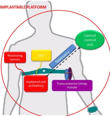
As described in Figure 1, the platform proposed in this thesis will be composed by different blocks: a central control unit (ARU), pressure (PRS) and flow (FLW) sensors, a transcutaneous energy transfer system (TET) and a telemetry system (TEL). Each component is introduced in the following paragraphs.
10
1.2
V
ENTRICULAR ASSIST DEVICEVentricular Assist Devices (VADs) are mechanical pumps used to reduce the payload of a deceased heart. VADs are implanted primarily in late stage congestive heart failure patients, in order both to facilitate cardiac recovery and, most often, to take time to the availability of a suitable heart. Nowadays, VAD systems have been proposed as a long term therapy alternative to heart transplantation.
In heart failure patients, therapy may include the need to reduce the cardiac workload and sustain systemic and coronary circulation by assisting mechanically the heart. In particular, mechanical pumps are usually used for this purpose in three different situations:
bridge-to-transplant: in end stage heart decease, the heart cannot be saved and the patient is supported by circulatory assist to sustain systemic circulation, while waiting for a donor heart, suitable for transplantation.
bridge-to-recovery: in patients with cardiogenic shock, myocardial infection or after a myocardial infarct, it is possible to try and save the heart by reducing the workload and/or increasing coronary circulation. In this way the heart may have sufficient time and circulation to recover.
destination therapy or alternative-to-transplant: this is an embryonic therapeutic field designed for end stage heart failure patients, that are ineligible for other therapies such as a heart transplant, and the only solution is a permanent circulatory heart.
About the history of mechanical circulatory devices, the first bio-engineering objective was to facilitate cardiac surgery. In 1952, Dr. Dodrill reported the first use of mechanical support to perform a mitral commissurotomy with left heart bypass. The addition of an oxygenator for cardiopulmonary bypass by Dr. Gibbon, in 1953, marked the beginning of open heart surgery. Use of circulatory support then expanded outside of the operating room, and in 1963, Dr. DeBakey, together with Dr. Liotta, implanted the first left ventricular assist device as acute support for a patient in cardiogenic shock [7]. In 1969, Dr. Cooley was the first to use an artificial heart to bridge an acutely deteriorating patient to transplantation 3 days later. In 1982, Dr. DeVries performed the permanent implant of an artificial heart as destination therapy. Recognizing that many patients would benefit from just left ventricular support instead of heart transplant, the
11
National Heart, Lung, and Blood Institute (NHLBI) established the Clinical VAD program in 1975.
In the 1970s and 1980s, several ventricular assist systems were developed and they are collectively referred to as first generation VADs. They were large devices characterized by pulsatile flow, artificial heart valves, and typical rates between 80 and 100 times per minute with the use of either forced air or electricity. The first generation VADs with FDA (Food And Drug) approval in the USA are the Thoratec PVAD/IVAD, the Heartmate IP/VE/XVE, and the Novacor LVAD.
The Thoratec PVAD (paracorporeal) and IVAD (implantable) employ a pneumatic pulsatile VAD and mechanical valves, in the inflow and outflow ports to ensure unidirectional flow. The pump alternates positive and negative air pressure states that actuate a flexible blood sac within the rigid casing. Its stroke volume is 65 ml, providing an output between 1,3 and 7,2 l/min at rates between 20 and 110 beats per minute (bpm). Thoratec PVAD received FDA approval as a bridge to transplant in 1995 and as a bridge to recovery in 1998. It has been implanted in over 1700 patients since its introduction but it is still too large for pediatric support.
The Heartmate IP (implantable pneumatic) was similar to the Thoratec PVAD and it received the approval as a bridge to transplant by the FDA in 1994. This model was later supplanted by the Heartmate VE (Vented Electric) and then the Extended Vented Electric (XVE) in 2001. The main characteristic of its design is a textured titanium and polyurethane blood contact surface, which limits thromboembolism. It provides, also, a
complete unloading of the left ventricle in refractory heart failure patients. A multicenter review of 146 VE and 98 XVE implants demonstrated the XVE decreased the major device malfunction at 1 year from 76% to 97%. The XVE received FDA approval for use as bridge to transplantation and destination therapy in 2003.
The Novacor LVAD is composed by two push-plates, electrically controlled, that compress a blood sac, forcing the blood to eject and two valves to prevent back flow. The technique used to pump the blood makes it possible to fill the pump without applying a negative pressure from outside. Novacor is characterized by a pump volume of 70 ml and a maximum flow of 10 l/min. It was demonstrated that the 75% of the implanted patients survive till transplant. Novacor received the FDA approval as a bridge to transplantation in 1988.
12
The need of increased durability, total implantability and smaller sizes brought to the development of the second generation VADs. These devices provide a continuous flow by using of a rotary axial pump which operates at high revolutions per minute (typical range: 8000–10 000 rpm). Compared to pulsatile VADs, the second-generation pumps
are smaller, quieter, easier to implant, last longer and simpler in design with a fewer moving parts and no valves. The main disadvantage is the increased probability of suction events and gastrointestinal bleeding.
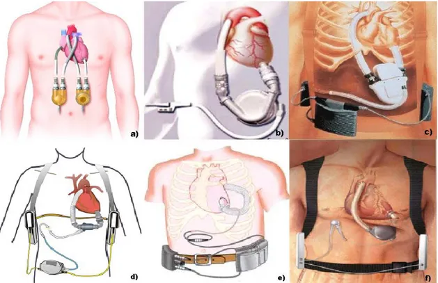
Figure 2 – a) Thoratec PVAD; b) Heartmate VE; c) Novacor LVAD; d) Heartmate II; e) Jarvik 2000; f)
Levacor VAD.
From the second generation class, only the Heartmate II has been FDA approved as a bridge to transplant in 2008. The pump utilizes rotor flow to propel blood, its rate ranges from 6,000 to 15,000 rpm and produces flows up to 10 lpm. It is exceptionally durable, dependable, and thromboresistant. The internal pump is placed in the preperitoneal space, also in smaller patients due to its smaller size. An external controller, with the size of an adult's hand, monitors the pump and allows the patient to leave the hospital and do most daily life activities.
Another second generation VAD example is the Jarvik 2000 FlowMaker. It is a titanium pump with a direct current motor and a size of a C battery. The normal operating range
13 for the control system is 8000 to 12000 rpm, which generates an average pump flow rate of 5 l/min. The external controller is responsible for the control of the pump speed and the monitoring of the pump function and the remaining power in the batteries. Currently, the Jarvik 2000 does not have full FDA approval, but only for bridge-to-transplant use investigational studies. In Europe, the Jarvik 2000 has earned CE Mark certification for both bridge-to-transplant and lifetime use.
Ongoing research and development has led to so called third generation VADs. These pumps utilize a design that is bearingless, for a more durable system, and centrifugal, for a flatter and more sensitive pressure flow curve at lower rpms, reducing the risk of suction events. Currently approved VADs are implanted just below the diaphragm in the abdomen, or can sit outside the body on top of the abdomen. A driveline that contains the power wires exits the skin, usually on the right side of the abdomen, and connects to a controller that is worn on a belt. This controller is then connected to either a power-based unit, that plugs into the wall, or a large batteries, that can be worn in a holster, or a vest for portable use. The controller is the brain of the pump, and provides important information to the patient, caregivers, and medical team about VAD function and battery life [8].
The Levacor VAD is one of the next-generation blood pumps. It is a compact, centrifugal pump, with a completely magnetically levitated impeller that guarantee greater clearances and more optimized blood flow. Levacor VAD is also characterized by enhanced blood compatibility, multi-year reliability and durability and imperceptible noise and vibration.
There are also multiple other ventricular assist devices developed for short-term support. The Abiomed circulatory support system is one of the most widely used and
provides temporary support for one or both sides of the natural heart in circumstances where the heart has failed, giving the patient's heart the opportunity to rest and potentially recover. Patients implanted of this device must remain in the hospital during the support phase. The AB5000 Ventricle is vacuum assisted technology, allowing the patient to be mobile. Multiple studies have shown that patient ambulation, or walking, greatly assists the recovery process. So the ventricle is equipped with a console that allow patients to leave their hospital rooms and walk on hospital grounds.
More in general, a VAD system, today, consists of a pump, partially performing the fluid actuation work, a control unit and a power supply. Traditionally, the pumps
14 employed in these systems are either displacement based pumps or radial-flow pumps. A displacement pump produces a pulsating outflow, inducing a mechanical force on a fluid, contained within a defined space, hence giving it motion. They are very large in size, excluding many patients from use, but easy to control due to their relative insensitivity to changes pre- and after- load conditions. Radial-flow pumps impart momentum to a fluid by a rotating device in the fluid, allowing for counter pulsation operation. They are generally much smaller, even suitable for pediatric use, but more difficult to control due to their high sensitivity to changing pre- and after-load conditions. The control unit monitors a number of physiological and physical parameters in order to control the way the pump works. The power supply is used to power the VAD and it may be external, requiring transcutaneous wires or tubes, or implanted (such as a battery) [3].
The VAD may be implantable or located outside the patient’s body. VADs may also be used for assisting the left heart, LVADs, or the right heart, RVADs, or simultaneously both the left and right heart, BIVADs (Bi-Ventricular Assist Devices). In LVADs, the inlet of the VAD is connected to the heart via a cannula and the blood is returned to the heart by another cannula, usually connected to the ascending aorta (Figure 3).
15
Figure 3 - Components of a typical VAD. It is typically placed through a chest incision after the patient has been positioned on a heart-lung bypass machine. A continuous-flow LVAD consists of a pump connected to the heart and aorta via an inflow and outflow cannula and a system controller that is typically worn on a belt. Power to the controller and pump is provided by external batteries or a power-based unit.
1.2.1SYNERGY™ DEVICE
The Synergy™ Device (Figure 4) is a LVAD pump by CircuLite (Aachen, Germany). The system is composed by CircuLite's proprietary micro-pump, an inflow cannula and an outflow graft, a percutaneous lead that is connected to a wearable external controller and a lightweight, rechargeable dual battery pack system. The pump has the size of a AA battery and provides up to 4.25 liters of blood flow per minute and it can be set to respond to the patient's cardiac output demands. The system is surgically implanted using a non-invasive mini-thoracotomy and the pump is placed in a pacemaker-like pocket.
The Micro-pump is characterized by a magnetically and hydrodynamically levitated and stabilized rotor motor and the design allows the avoidance of the contact between the blood and the motor and the minimization of the potential of thrombus formation.
16 The dual battery pack system is connected to the micro-pump via a percutaneous lead that exits the body in the abdominal area and power the SYNERGY system. The controller provides the patient with information on the battery status and alerts the patient to any change that needs attention.
An important feature of the SYNERGY system is its ability to work in conjunction with the patient's remaining native heart function. In the event of accidental power disconnection, patients may be supported by their remaining cardiac output until power can be restored to the system.
Figure 4 – SYNERGY device from Cyrculite
In the in-vitro setup for testing and validation, the device is fastened to an homemade hydraulic circuit made by a silicone tube, 3/8x1/16‖ inches (internal diameter x wall thickness) in size, connected to a tank filled with the fluid to be pumped into the flow
17 loop. The fluid contained the 48.3% of glycerine and the 51.7% of water to simulate the viscosity of blood and to avoid the bearings damage of the pump.
This LVAD has been used in the in-vitro scenario, which is exploited as test-bench to design and test the implantable platform proposed in this thesis.
18
1.3
C
ENTRALC
ONTROLU
NITAlthough the patients are well educated about the management of the device before the discharge, a continuous remote automatic monitoring system could add far more reliability and safety to the management of the device and the patient.
Together with the reduction of the ventricle workload, the pump also improves its oxygen supply, by increasing systemic arterial pressure. In the heart, the control is provided by the so called Frank–Starling mechanism [5], whereby stroke volume increases in response to the increased diastolic filling as a result of increased venous pressure. This behavior, which is mediated by the contractile properties of the myocardium, ensures a cardiac response to increased physiological demand. This local control is normally overcome by the central response, which acts by neural and/or humoral mediators and leads to an increased strength of contraction, reducing the endsystolic volume and increasing the heart rate. In heart transplant the central neural humoral responses are absent, as well as in VAD patients is absent. In this cases, the Starling mechanism alone suffices to regulate heart action. In this situations, there is not the same elastic ability of the organ to vary the stroke volume as in the natural ventricle anymore, so the control response is usually based on the control of the pump rate [9]. Thus, a recent aim of the physiological control system of rotary LVADs is to bring the patients’ abnormal haemodynamic variables back to the normal range. Different variables have been proposed as criteria of normal condition. Some are critical and must be satisfied, such as:
A1) providing normal blood flow,
A2) maintaining arterial pressure within normal physiological range, A3) avoiding pulmonary congestion,
A4) avoiding left ventricular suction.
A3 means that the left atrial pressure (LAP) or the left ventricular end diastolic pressure (LVPED) is less than an upper limit. The violation of this limit over extended period can cause severe problem like pulmonary congestion. This limit may be patient specific, but 15 mmHg is a general good reference. A4 implies that the LAP or LVPED must be maintained above a time-critical lower limit, usually the pleural pressure, so that the collapse of left ventricle will not happen. It is worth noting that all the key criteria are
19 about hemodynamic variables, which are co-dependent on each other. These criteria are satisfied at the same time for a normal person, but may not for a CHF patient with a LVAD, due to the remodeling and compensation mechanism of the body. A1 and A2 are treated with equivalently importance. There is no conclusive remark about which one should be selected if A1 is in conflict with A2. A3 is not as time critical as A1, A2, and A4, and usually deem to be true if A1 or A2 are satisfied.
Other proposed criteria, which are desired but not critical, are classified as secondary, such as:
B1) maintaining nonzero left ventricular outflow B2) maintaining positive pump flow
B3) robust performance.
B1 is to make sure that aortic valve is open for a portion of the heart cycle, preventing the blood stagnation on the backside of the aortic valve. If the natural heart is too weak, this criterion may not be achieved when A1 is satisfied, but can be compensated by anti-coagulation drugs. B2 is to prevent the regurgitation of blood back from the aorta to the left ventricle in diastole, which in fact is acceptable at small amount. B3 is to guarantee the reliable performance of rotary LVADs in the presence of physiological state variations. This one is particularly important for long term application of rotary LVADs.
Some examples of control algorithm used over the years will be discussed in the following.
Parnis et al [10] used a proportional controller for the Jarvik 2000 VAD. Heart rate was obtained from the fundamental frequency of the motor current (I) waveform and set as a linear function with the pump rotational speed (ω). A limitation for this approach is the fact that a linear relation was supposed between the heart rate and the angular speed of the pump. In CardioWest C-70 and in the Utah Electrohydraulic Total Artificial Heart, the measured heart inflow pressure was used as the parameter to control cardiac output. The correlation between in-flow pressure and pumped volume has been well established and it is depicted in Figure 5.
20
Figure 5 - Cardiac output vs Right atrial pressure
The same could be done with mechanical blood pump: a commutator controls the motor speed at a constant level that is requested from the physiological controller. The control law for the last one is implemented to duplicate the curve in Figure 5 is duplicated. The atrial pressure reference input can be changed to shift the curve along the x-axis depending on individual patient requirements.
Another example is given by Giridharan et al [11]. They proposed a different approach to physiological control of rotary blood pumps. Their method allows to implement an automatic response to changes in demands of physiological perfusion by maintaining a constant average pressure difference between the left ventricle and the aorta. Such system requires the implantation of two pressure sensors and the development of a gain scheduled proportional integral (PI) feedback controller.
The target of the control strategy is to achieve the physiological perfusion and this is done when the blood pump maintain and average pressure difference (ΔP) between the left ventricle and the aorta, close to a reference pressure (ΔPr). The feedback control algorithm will regulate ω within physiologically acceptable limits while minimizing the difference between ΔPr and ΔP.
Moreover , it is very important to keep oscillations of ω as low as possible in order to guarantee a longer pump life and patient's comfort. The electrical current of the pump (I) is used as a control input and it is subject to an inequality constraints ωmin ω(I)
ωmax, such that the quadratic objective function is minimized.
Where ωmin and ωmax are functions of the blood volume in the left ventricle, is the rate
of change of ω where this should satisfy the system of nonlinear hybrid equations which describes the circulatory system assisted by rotary blood pump. In order to maintain
21 ΔPr as much constant as possible, a proportional integral controller was selected to manipulate I according to the following control law:
where ΔP is the measured head pressure. The proportional (Kp) and integral (KI)
constants were selected to minimize J for different weighting. Different values for Kp and KI to minimize J were obtained for two different types of rotary blood pumps: for
an axial pump and a centrifugal pump. Tests were done using this controller and results showed that maintaining a constant average pressure difference between the left vetricle and aorta resulted in physiological perfusion over a wide range of physiological conditions including rest, light and strenuous exercise levels.
Another example of control algorithm was the one proposed by Bullister et al in 2002 [12]. It is a hierarchical algorithms whose aim is to control and monitor the blood pumps using pressure inputs measured by APEX pressure sensors (APSs) at pump inlet and outlet. The control algorithms has two level in order to adapt to various left ventricular diastolic filling pressure (LVDFP). The main goal of level 1 is to keep the LVDFP within a physician-programmable range. This was done by means of an integral control algorithm implemented with pump inlet pressure (Pin) where this was used as an input and the pump speed control signal as the output. Moreover, level 1 outer loop control is also charged to maintain the arterial pressure within programmed limits and has a slower response time than the inner control loop. In particular, the outer loop changes the LVDFP set point of the nested inner loop when the arterial pressure reaches the programmed limit values.
On the other hand, level 2 control algorithm was implemented as an outer control loop around the inner level 1 control loop. The control input is the outlet pressure (Pout), while the control output is the modified target LVDFP, that is sent to the level 1 control loop. When level 2 is active and the pulse rate is above a certain threshold, the desired target value for LVDFP is continuously updated to provide the feedback control for the target arterial pressures. So, the mean arterial pressure controlled by level 2 is kept constant thanks to an intermediate mechanism that actively adjust the level 1 effective target value of the LVDFP within its working ranges.
A very common problem that must be prevent in continuous LVADs is the collapse of the left ventricle. For this reason, Wu et al proposed a proportional integral controller
22 whose target is to minimize the sum of the aortic pressure tracking error and weighted head tracking error. In fact, during heart cycle, aortic pressure should be maintained relatively constant. However, during dramatic physiological disturbances such as a sudden change from rest to exercise, the left ventricular collapse may occur even if aortic pressure is maintained as constant as possible. When ventricular collapse occurs, the pressure and blood volume in the left ventricle decreases; as a consequence, a very efficient way to detect the onset of the ventricular collapse could be the monitoring of the difference of pressure across LVAD. This explains the necessity of controlling both the aortic pressure and the difference in pressure between the ventricles.
However, for invasive and non-invasive techniques, control algorithm had been developed over the years in order to control physiologically and adaptively the left ventricle assist devices and to avoid undesired phenomena, such as pumping states of left ventricular in which a collapse is caused by suction. The main requirements for this automatic control system are to ensure stable, reliable operation and to work at high power efficiency. Moreover, for long-term use, the control algorithm must stabilize the operation of the blood pump and meet changes in physiological demand.
The most frequent strategies, used to sense and monitor the relevant parameters for heart assisting devices, are based on:
measurements during the act of driving the pump electrically,
measurements of fluid-mechanical variables by incorporation of transducers,
solutions in which the fluid-mechanical variables of pressure drop and flow-rate have been estimated indirectly,
solutions in which suction and/or valve non-opening are detected,
solutions in which the measurements available to the pump controller can be used to assess natural heart function,
use of other sensors for miscellaneous purposes (such as fault detection).
The pressure transducer method is the most used one both because the sensors would allow the real time adjustment of the assistance device performance, thanks to a feedback loop, and because this method is used as a standard of comparison for other proposed control methods.
23
1.4
M
ONITORING SENSORSThe selection of suitable sensors that detect the changes in the body’s metabolic demands is one of the important goals in designing LVADs control systems.
Presently, most of the pumps derive all their information from the pump’s power consumption but use this information predominantly to monitor (to detect suction, low flow conditions, pump stoppage) and to trigger alarms. If the pump would be sensorized, it can take advantage also from physiological signals acquired by a set of sensors, all communicating with the auto-regulation unit, in order to monitor not only the status of the LVAD but also the patient.
Physical sensors could also allow assessing patient/LVAD hemodynamics relationship during assistance, in order to detect the contribution of the native heart. This issue may become important when the effect on recovery of drugs or other therapy (e.g. stem cells) has to be evaluated. Finally, monitoring native heart function during daily activity may give information about the effect of skeletal muscle endurance on myocardial recovery.
The sensors that can be used in the physiological control system of VADs are limited by the market and physical constraints. Physiological sensors are those sensors that can directly measure the cardiovascular physiological variables. Potential physiological sensors used in LVADs include oxygen saturation sensor, pressure sensor, flow rate sensor, and acceleration sensors [14].
Because of their high flow impedance and complication of blood clotting, the conventional flow sensors have never been used in any implantable LVAD. But, in this case, the flow rate information is highly desired, so the high accuracy ultrasonic flow meters are used. This type of flow sensor can be clamped outside the LVAD pump outlet cannula to measure the flow rate without surface contact with blood. Thus, they are totally impedance and thrombosis factor free.
Pressure sensors are also very important, in fact they have been suggested as an effective method for controlling a LVAD. As discussed in the previous paragraph, several control algorithms are based on the directly measured pressure feedback. Conventional pressure sensors are mainly used in LVAD applications only for the short term because they are responsible of drift and thermal problems. Fortunately, in the last years, they have been developed in a manner that might provide a longer working
24 period. For example, Apex Medical Inc. has designed what they have claimed to be a long-term implantable pressure sensor, called APS [15]. This pressure sensor uses a pressure-sensing diaphragm that can be built into the wall of any titanium pump or inlet cannula.
Physiological sensors are also grouped into two classes: the ex-body sensors for patient monitoring, and in-body sensors for VAD and patient monitoring. The in-body sensor data and VAD pump data will be sent through the body using a medical standard wireless protocol like MICS. In the case of continuous powering through an inductive link, it is also an option to retrieve the data through a load-modulated uplink, or send data to the VAD by power carrier modulation. Ex-body sensors for patient monitoring can be hardwired to the hardware unit, or connected through the same wireless protocol. By using hardwired sensors the problem is to overcome and to foresee a separate power supply for every sensor node.
25
1.5
T
RANSCUTANEOUSE
NERGYT
RANSFERS
YSTEMThe purpose of a transcutaneous signal transmission is to develop a system that transmit signals to and from a left ventricular assist device, leading to a decrease of the amount of cable through the skin. In the first project of the LVAD, the percutaneous cables were 23 with a diameter of 8mm. Over the year, the design process allowed to decrease the number to 7 cable and the cable diameter to 2.7 mm. This was possible by changing the placement of components as well as implementing a communication protocol, SPI, capable of transmitting and receiving the required signals through the same cable. Moreover, this cables are very stiff and they cause discomfort, limited range of motion and many health risks to the patient, because the exposure of the tissue to the cable increases the risk of infections.
For all these reasons, a transcutaneous energy transmission system was designed in order to exploit the capacity of time varying magnetic fields to transfer power across the skin to drive implantable biomedical devices without the use of any percutaneous wire. Using inductive coupling, a primary coil located on the outside of the body would transfer the required energy to a secondary coil located on the inside of the body. In order to induce a magnetic field between the two coils, an AC power source is added. The only power supply available is a DC battery; therefore an inverter is designed to convert the energy. The power efficiency is found to be 10% over the system and 27% over the coils [18].
To bring some example, it is possible to mention the TET system proposed by Carr et al [18] (Figure 6). Here, a PWM controller was used to create a different frequency square wave. The coils used were 7 cm in diameter and made of 20 and 75 turns respectively. This ratio was determined in order to compensate the voltage drop across the coupled coils. It was also added a supplementary battery pack in order to prevent accidental power failure. For this reason, a switch was added and it is capable to read the input voltage of the pump. In this way, if the TET voltage dropped below 14.8V, the backup battery would power the system until the TET power reached a suitable level. The controller used for this TET is an open-loop system and its setting can be adjusted only by human intervention.
26 Future development could oversee the implementation of a feedback network to close the control loop in order to fulfill in every moment the desired condition.
Figure 6 - Schematic of Carr et al. TET
An other example is the TET system designed by Dissanayake et al [19], it is used a DC voltage that is supplied by an external battery pack. A current resonant converter is then used to generate a high frequency sinusoidal current across the primary coil in order to produce a sinusoidal voltage in the secondary coil that is then rectified by the power conditioning circuit to provide a stable DC output in the implanted device. As shown in Figure 7, a DC inductor is added to the secondary pick up following the rectifier bridge in order to maximize the power transfer to the load. The DC inductor is important to sustain a continuous current flow in the pick up.
27 Two transceivers are also integrated for data communication. The internal transceiver send the detected DC output voltage of the pickup to the external transceiver, through a RF communication channel. Then, the external transceiver task is to process the data and adjusts the duty cycle of the output PWM signal. In this way, the reference voltage (Vref) of the frequency control circuitry is adjusted and a Digital to Analogue Converter (DAC) is used for the PWM signal in order to obtain a variable reference voltage. By this variable reference voltage the frequency of the primary resonant converter is varied and, as a consequence, also the power delivered to the implantable system changes. With respect to the state of the art, one of the main improvements of the proposed platform is the replacement of wired with wireless links to maintain not just two way data transmission, but also power support for the implant.
A TET system is basically a DC-DC converter built around a loosely coupled transcutaneous transformer. The primary coil, placed outside the body, is driven by a switching amplifier and it generates a magnetic field, which is partly picked up by the secondary coil, hereby, inducing a current. After rectification, a regulator or a feedback loop are used to ensure a constant output voltage despite variations in coupling factor or power drain.
From a technical standpoint, the transmitted power amount can vary from a few mW up to several W in the appropriate coupling conditions. The TET system will be used in synergy with an implantable rechargeable battery pack that will serve as a backup solution in case TET will fail or whenever the patient will need to stop TET (e.g. to take a shower), as safety norms request. Adoption of an implantable battery pack will drastically reduce failure risks related to the platform and give to the patient the opportunity to be free from cables for a while.
Furthermore, some issues about change in energy delivering have to be solved. For example the coupling between the external and internal coils will vary according to their orientation and posture or other potential sources of power delivery variations, arise from changes in circuit parameters and loading conditions. In order to maintain correct device function, the power delivered must be regulated to face these variations.
For these reasons, compared to percutaneous wires, TET systems is more complex to be managed and to operate under variable coupling conditions, because, in the majority of the cases, it result in a variation of the power transferred to the device. The typical
28 separations between the internal and external coils are in the range of 10-20 mm. If insufficient power is delivered to the load then the implanted device will not operate properly. If excessive power is delivered, then it must be dissipated as heat with the potential for causing tissue damage. Therefore, it is important to deliver the right amount of power matching the load demand.
The design of an inductive link for the supply of high power consuming implants is far from being a trivial task because it is necessary to include high efficiency, stability, reliability and patient’s safety. A continuous compromise between power transfer efficiency, system dimensions and respect of safety standards, is the biggest challenge. Most relevant parameter is the implant power consumption: the higher the required power, the stricter becomes the freedom in the magnetic design. In high power systems all the possible sources of power loss have to be drastically reduced, and must include a feedback loop to constantly adjust the externally applied power.
From the regulatory standpoint, a specific energy absorption rate (SAR) up to 10W/kg is considered safe for operational exposure of head or trunk for an operating frequency below 10MHz. This SAR value is unlikely to produce any detrimental health effects on humans. By properly selecting the carrier frequency and by accurately design the TET system, a SAR below 10W/kg is considered a feasible threshold to comply with in order to supply an average of 11 W to the implanted system. It must be said the ICNIRP norms [20] are to be intended as a preliminary margin of a matter that is still to be investigated by the scientific community. This indication is really strict at the moment but the real tolerability limit is probably higher. Theoretical study and in-vivo testing will help in defining how this limit can be extended. On the other hand, improving the energy transfer efficiency (e.g. using a ferrite core in the secondary coil) will allow transmitting the target power amount, limiting the external magnetic field, fully complying the current limits.
29
1.6
T
ELEMETRYBiomedical telemetry has been used primarily for the measurement of physiological signals at a distance, through wireless communication technologies. Physiological signals are acquired by means of a transducer, then post-processed and transmitted to an exterior monitor or a control equipment. But, one of the latest developments of biomedical telemetry is in the field of implantable medical devices (IMDs). Millions of people worldwide depend upon implantable medical devices. In fact, RF-linked implantable medical devices are already in use for a wide variety of applications, such as temperature monitors, pacemakers and defibrillators, functional electrical stimulators (FES), blood-glucose sensors, and cochlear and retinal implants. Usually they work on the MICS (Medical Implant Communication Service: 402 – 405 MHz ) band, because of its advantages of being available worldwide and being feasible with low-power and low-cost circuits. This band reliably supports high-data-rate transmissions, falls within a relatively low-noise portion of the spectrum, lends itself to small antenna designs and acceptably propagates through human tissue. The critical point of the RF-linked implantable medical devices is the integrated implantable antenna, which enables the bidirectional communication with the exterior [22].
High frequency antennas dedicated to medical implants are rare in the literature but there is a number of different antenna designs that may be adapted for IMDs. Coil antennas are used for biomedical telemetry at low frequencies because they are compact when used in short distance links. One classic design is to use the tuning coil of the oscillator as the antenna, and thus get the antenna for free. Modern IMDs use far-field radio-frequency (RF) telemetry, which mainly are resonant electric antennas, in contrast to the coil antenna, which is a magnetic antenna. The implant and the base station contain a RF transceiver and use radio-frequency for communication. The communication range for RF telemetry is much longer than inductive telemetry (Figure 8). However, the implanted battery also needs to power the RF transceiver, so RF telemetry consumes much more energy than inductive telemetry.
30
Figure 8 - Inductive Telemetry vs. RF Telemetry: (a) – During/Post Surgery, (b) – Follow-up Clinics, (c) – Home Monitoring
An interesting telemetry system was developed for a wireless endoscope by Shirvante et al. [21]. The system consists of a thermally stable low power transceiver, a microcontroller, a balun, and an antenna. In particular, a wide band antenna for transmitter and a narrow bandwidth antenna for receiver were designed. The receive antenna is a compact spiral monopole antenna with an area less than 100mm2. The overall length of the wire is approximately a quarter wavelength: λair /4 = 187mm at 402MHz for air medium. For the transmit antenna, it is necessary to consider the environmental variations. The pill experiences a change of relative permittivity and conductivity in the range of 40 to 70 and 0.08 S/m to 1.9 S/m, respectively, as it travels from mouth to intestine. A permittivity εr of 55 and a conductivity of 0.7 S/m have been
used for simulation. The overall length of the antenna is selected in order to have λbody/4=λair/4√εr= 26mm.
An other example is the one from Kiourti et al.[22] who proposed patch design for implantable antenna and did numerical and experimental investigations in order to demonstrate its biocompatibility. This type of antenna are highly flexible in design and
31 shape, thus relatively simple to miniaturize and integrate into the shape of the IMD. For example, the hardware can be mounted on the existing hardware of the device to serve also as the ground plane. Patch antennas are also patient safe and guarantee high-quality communication with exterior equipment.
However, antennas for implantable telemetry systems are generally electrically small antennas, like most of antennas for wireless applications, but the implant will be located in a complex lossy medium and this influences their performance. Thus, it is necessary to investigate the electromagnetic properties of the human body in order to design a suitable antenna. Classical antenna theory mainly deals with radiating structures placed in vacuum or in air; this means that they are placed in a non-conducting environment with a permittivity of ε0 = 8.854 * 10^-12 F/m. While, when the antenna is placed in a
material with a higher permittivity, and with non-zero conductivity, the usual simplifications cannot be used [23].
The general challenge of an implantable antenna design is that the behavior of an free-air antenna is radically different from an implantable antenna due surrounding tissue with different electrical properties. Indeed, the human body consists of different tissue types as skin, muscle, fat, bone, blood (
Figure 9).
Figure 9 - Dielectrical properties for tissue at 403.5 MHz [23].
Due to the fact that the wavelength of electromagnetic wave in dielectric matter prolongs, the dimensions of an implantable antennas can be designed shorter. The shortening factor could be expressed by the following equation:
32 By applying this equation a shortening factor between 2.3 (fat) till 7.5 (muscle, blood) can be calculated.
Furthermore, the analysis of the radio link has to consider a wave propagating not only from the antenna through the body but also into the air and over to the base-station antenna. It is hard to characterize this propagation, especially the radiation pattern from the implant one. Another complication is that the radiation characteristics are influenced by the tissues in the near-field of the antenna, and thus vary between different patients. It is necessary to consider the following design challenges and restrictions in order to design an implantable antenna:
size limitations mean that careful considerations in design must be made,
power consumption must be minimal during data transmission,
for the MICS band, a limited ERP (effective radiated power) of 25μW is required outside of the body,
materials for biomedical implantation are limited to titanium, platinum or PEEK (Polyether ether ketone) (system can be encased as well),
cannot have DC potential to the system nor the body,
RF Losses in tissue (see Figure 10).
33 The main objective has not been to find the best antenna for use in a medical implant, but to get a valid figure for a reasonable antenna performance to be expected from a medical implant.
The simpler way to perform a successful design is following these steps:
Choose an antenna type to be used (dipole, helix, loop antenna), depending on the required bandwidth, the communication electronics and the volume available.
Perform an initial design considering a homogeneous lossless medium surrounding the antenna. In this way, the advantages are speeding up the simulation time and ensuring that the bandwidth reached by the antenna is "real" bandwidth and not due only to losses in the body.
Miniaturize the design.
Re-tune the antenna, after adding the losses in the homogeneous body model and the cover.
Add a more realistic body phantom as the medium surrounding the antenna. Re-tune the antenna.
34
1.7
P
ROPOSED IMPLANTABLE PLATFORMA revolutionary approach to reach the aforementioned aim could be the development of a implantable platform integrating on the VAD miniaturized innovative flow and pressure sensors and implementing a continuous monitoring strategy, with the purpose to optimize and personalize the heart unloading degree.
This implantable platform is one of the topics introduced in the framework of the European project SensorART (a remote controlled Sensorized ARTificial heart enabling patients empowerment and new therapy approaches).
The main goal of this project is to better understand patient-device interactions by providing technological improvements centered on the development of: wearable sensors, artificial intelligent algorithms, light-weight portable hardware controllers and ―smart‖ signal processing algorithms. The advantages of such platform could be the steering and optimization of the pump function without intervention of a care-taker, thus leading to a greater independence of the patient and to the reduction in costs for personnel to realize home support. It could also be possible to study the biohumoral signals during the assistance and cellular changes before and after the assisting therapy and to measure the natural heart delivery capacity according to the assisting time.
The different hardware and software components, included in SensorArt, could lead to the development of an open, interoperable, extendable system that improves the quality of the patients treatment as well as the workflow of the specialists.
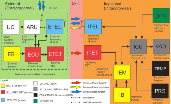
In particular this system will include different modules (Figure 11). It integrates sensors, signal acquisition module, hardware controller, a remote control framework and a decision support system.
Figure 11- Block diagram of the proposed platform.
35 Therefore, the main components of the implantable platform are: the LVAD, the implanted flow and pressure sensors embedded on the pump, a transcutaneous energy transfer system, a telemetry system, for data transfer to the external unit, and a remote data management for the wireless transfer of data collected by the implanted sensors.
Figure 12 - Implantable components and units
The sensor module, measuring pressure and flow, is used to monitor both the status of the LVAD and of the patient. The LVAD and the embedded monitoring sensors will be integrated in the self-contained implantable platform. This platform is in a closed loop with a central control unit, namely Auto-Regulation Unit (ARU), that ensures a continuous monitoring and a feedback control of the parameters. The ARU is an external and wearable hardware unit wirelessly linked to the implanted sensors and to the VAD actuators, which implements the control algorithms; in particular, it acquires and stores data, controls the status of the VAD and it is able to set the pump by direct intervention of the cardiologist or in an auto-regulation loop based on sensors data output. The transcutaneous energy transfer (TET) is able to deliver a stable DC power for VAD driving, including additional power for charging batteries. The RF link is a bidirectional telemetry operating in the worldwide accepted frequency range from 402 – 405 MHz (Medical Implant Communication Service: MICS), that allows wireless communication between the implantable platform and the extracorporeal system components.
Some development steps and measurements for the evaluation about each component of the implantable platform will be described in the following chapters.
36
CHAPTER
2
2.1
T
HEA
UTO-R
EGULATIONU
NITAs previously said, the ARU is the unit that implement an intelligent control algorithm, with the purpose to optimize and personalize the heart unloading degree.
In the proposed sensorized platform, the auto-regulation control algorithm will be implemented in an external and wearable hardware unit, wirelessly linked to implanted sensors and to VAD actuators. This unit will allow to auto-adjust the blood flow, provided by the VAD to the patient’s heart, according to signals coming from sensors. It is based on control algorithms able to work in real-time by using adjustable thresholds and control parameters. Moreover, this unit will monitor the energy consumption, as well as the VAD functionality, thus generating the appropriate crucial and vital alert messages.
As stated in the first chapter, currently known methodologies for adjusting pump parameters imply a manual setting of the pump speed until the patient perceives a comfortable level of perfusion.
In this particular case, the physician chooses a proper level of perfusion and sets the corresponding flow value through a dedicated interface. According to this value, the implemented control algorithms automatically send to the pump controller the proper command to change the rpm. The target value is reached by the implementation of a Proportional-Integrative (PI) control that dynamically and precisely changes the pump speed in order to achieve the desired flow value. This control method has been implemented since it allows a fast, fine and stable reaching and maintaining of the desired flow.
A second kind of control algorithms has been implemented to monitor the pump status through checking drops in pressure values. The aim of this check is to monitor if high, fast and/or repetitive changes in the pressure values occur. In particular, these changes could be the signal for a LVAD malfunctioning such as the presence of a suction event that could negatively affect the patient condition and suddenly provoke thrombus formation. To avoid this problem, a threshold control on drop pressure variation has
37 been implemented in order to reset the pump if pressure oscillations are detected.
The control algorithm was implemented using the LabView development environment and run, in a first phase, on one PC. Then, for problems related to computational load, it has been split on two different and dedicated PCs, thus simplifying suitability and feasibility test of the proposed control method. The hardware components of the platform are connected only to the first PC, named ―Acquiring PC‖ which has the task to acquire and store all the data. While on the second PC the algorithms run, processing these data and creating the command that have to be send to the pump controller. This second PC is named "Control PC". The logic work flow used to implement the control unit and all the communications are showed in Figure 13.
Figure 13 - Logical work flow of the ARU
A first functionality for the ARU is implemented in the Acquiring PC, which continuously acquires, visualizes and stores both flow and pressure data and the values of speed and current from the pump controller. These data are constantly collected and converted into format strings in order to be transmitted to the Control PC. For every running cycle the latter continuously controls pressure and flow values. In particular, as regards the flow control, the algorithm checks, at every cycle, if a new desired flow value is set into the interface. When a new value is inserted, the system compares it to the current flow value and, through a case structure, discerns two different conditions:
1. the desired flow is higher than the actual read; 2. the desired flow is lower than the actual read.
38 A PI controller was selected in order to obtain the increment or decrement needed for reaching the desired flow, and directly change the pump speed. The theoretic basis of the PI controller are reported in [13]. The PI controller was implemented in LabView with the transfer function form according to the following law (1):
where KP and Ti represent respectively the proportional gain and the integral time. A
manual tuning was used to define their proper values. U(s) represents the Laplace transform of the controller output and E(s) the Laplace transform of the inlet. In our implementation E(s) is calculated depending on the situation detected by the case structure. Considering FD the desired flow value insert by the clinician and FA the actual
read flow value:
1. E(s) is the Laplace transform of (FD - FA ) when FD is higher respect to FA;
2. E(s) is the Laplace transform of (FA - FD ) when FA is higher respect to FD.
In order to minimize the difference between flow values, the PI will return in output U(s), which is the quantity in rpm that must be added or subtracted to the actual value. As explained above, the activation of the PI controller depends on the insertion of a flow value into the interface. Conversely, the control on pressure is a really automatic control, continuously active for every running cycle of the program. A threshold control on the standard deviation of the average pressure drop values is implemented. More in detail, a 100-samples-long dynamic array is assembled and updated as soon as a new pressure value is available, and its standard deviation (σ) is calculated according to the following law (2):
where n is the number of samples (n=100 in our case) and µ their mean value. The standard deviation of the dynamic array is continuously monitored and compared to a pre-defined threshold. In order to define an accurate and suitable threshold value for the implemented pump, a specific test was carried out keeping the pump in a steady condition (i.e. no suction or any instable events occurring). The standard deviation in these conditions has been evaluated in order to define the pressure variation during normal working operations of the pump. Then, the same test was carried out simulating a suction event to define the typical standard deviation in this case. By these measurements
![Figure 36 - Trend of the temperature (Absolute value [°C]) of the silicone surface of the coil with a constant current load of 800mA](https://thumb-eu.123doks.com/thumbv2/123dokorg/7626445.116786/72.892.256.692.767.1069/figure-trend-temperature-absolute-silicone-surface-constant-current.webp)
![Figure 40 - Red curve: trend of the temperature (Absolute value [°C]) of the inner part of the coil with a constant current load of 800mA](https://thumb-eu.123doks.com/thumbv2/123dokorg/7626445.116786/75.892.245.693.237.563/figure-curve-trend-temperature-absolute-value-constant-current.webp)
![Figure 41 - Red broken line: relation between the coil surface temperature difference with respect to the environmental temperature [°C] and the vertical misalignment [mm]](https://thumb-eu.123doks.com/thumbv2/123dokorg/7626445.116786/76.892.228.688.297.660/relation-temperature-difference-respect-environmental-temperature-vertical-misalignment.webp)
