Universit`a degli Studi di Roma
“Tor Vergata”
Facolt`a di Scienze Matematiche, Fisiche e Naturali
The GEM detectors for the innermost region of
the forward muon station of the LHCb
experiment
Dottorato di Ricerca in Fisica - XX Ciclo
Matteo Alfonsi
Tutor
Coordinator
Contents
Abstract 1
1 The LHCb experiment in the actual physics scenario 5
1.1 The LHC project . . . 6
1.2 The proton-proton interaction setup at LHCb . . . 9
1.3 The LHCb apparatus . . . 11
1.3.1 The vertex detector system . . . 12
1.3.2 The RICH detectors . . . 14
1.3.3 The magnet . . . 15
1.3.4 The tracking system . . . 16
1.3.5 The Calorimeters system . . . 17
1.3.6 The Muon system . . . 18
1.4 The LHCb trigger . . . 19
1.4.1 The Level-0 trigger . . . 20
1.4.2 The High Level Trigger . . . 20
1.5 B-physics performances and sensitivity at LHC experiments . . . 22
1.5.1 B-physics at LHCb, ATLAS and CMS experiments . . . 24
2 The Muon System 27 2.1 Physics requirements . . . 27
2.2 General detector structure . . . 28
2.3 The station layout . . . 30
2.4 The level-0 muon trigger . . . 32
2.4.1 Background environment . . . 34
CONTENTS
2.5.1 MWPC detectors . . . 36
2.6 Electronics . . . 39
3 The Gas Electron Multiplier 41 3.1 From Multiwire Proportional Chamber to Gas Electron Multiplier Detectors 42 3.2 The GEM idea . . . 45
3.2.1 Influence of hole diameter . . . 47
3.2.2 Influence of hole pitch . . . 47
3.2.3 Influence of hole shape . . . 48
3.3 The single GEM detector . . . 49
3.3.1 The gap electric fields . . . 51
3.3.2 The drift gap thickness . . . 53
3.3.3 The induction gap thickness . . . 53
3.3.4 The GEM voltage . . . 54
3.4 The triple-GEM detector . . . 58
3.4.1 The transfer electric field . . . 59
3.4.2 The transfer gap thickness . . . 60
3.4.3 The GEM voltages . . . 63
3.5 The time performance . . . 65
3.6 The signal formation . . . 68
3.7 The R&D activity on triple-GEM detector . . . 69
3.7.1 Effective gain measurement . . . 71
3.7.2 Rate capability . . . 73
3.7.3 Time and efficiency performances . . . 73
3.7.4 The discharge process . . . 76
3.7.5 The ageing process . . . 80
3.8 Conclusions of the R&D activity . . . 84
4 The triple-GEM detector in LHCb 85 4.1 Detector overview and requirements . . . 85
4.2 Chamber components and design . . . 90
4.2.1 The honeycombs panels . . . 90
CONTENTS
4.2.2 The GEM foil . . . 95
4.2.3 The frames . . . 97
4.3 Chamber construction and tools . . . 98
4.3.1 The stretching of the GEM foil . . . 101
4.3.2 Mechanical specifications . . . 105
4.3.3 Quality check . . . 109
4.3.4 The detector integration . . . 112
4.4 The detector electronics and services . . . 114
4.4.1 The CARDIAC-GEM front-end boards . . . 114
4.4.2 The High Voltage System . . . 116
4.5 The global irradiation test . . . 119
4.5.1 Test setup . . . 119
4.5.2 Test results . . . 122
4.5.3 Gain and rate capability measurements on aged chambers . . . 123
4.5.4 Beam test results on aged chambers . . . 125
4.5.5 SEM analysis and X-ray spectroscopy on aged chambers . . . 126
4.5.6 Global ageing test conclusion . . . 131
4.6 The detector performance at the SPS 40MHz beam . . . 132
4.6.1 Test setup . . . 132
4.6.2 Time synchronization of detector signals . . . 134
4.6.3 Test results . . . 136
4.7 Conclusions . . . 138
5 A selection of the dimuon rareD0decay at LHCb 139 5.1 D0 → µ+µ−in Standard Model and beyond . . . . 140
5.2 Selection strategy at the LHCb experiment . . . 142
5.3 The LHCb software framework . . . 144
5.3.1 Event generation . . . 145
5.3.2 Event digitization . . . 147
5.3.3 Event reconstruction . . . 148
5.3.4 Event Analysis . . . 150
CONTENTS
5.4 Analysis procedure and results . . . 152
5.4.1 Selection cuts . . . 153
5.4.2 The effect of the L0 trigger . . . 156
5.4.3 Selection summary and results . . . 157
5.5 Final considerations . . . 159
Conclusions 160
Bibliography 163
Abstract
The LHCb experiment will take place at the LHC accelerator at CERN and will start in 2008. It is dedicated to precision measurements ofCP violation and rare decays in the b quark sec-tor.
The apparatus is a single arm spectrometer and it is designed with a robust and flexible trigger in order to extensively gain access to a wide spread of different physical processes involving
beauty particles. This will allow to over-constrain the Standard Model predictions aboutCP
violation, and to discover any possible inconsistency, which would reveal the presence of “New Physics” beyond the Standard Model.
This thesis reports the work performed on two aspects of the LHCb experiment: the main contribution is the development and the construction of a detector based on Gas Electron Multiplier (GEM) technology for the instrumentation of the high irradiated region around the beam pipe of the forward Muon Station; in the second part the possibility of the search of the rare D0 → µ+µ− decay at the LHCb experiment is investigated, demonstrating that
the experiment can found application also in the charm sector physics.
The triple-GEM detectors equipping the inner region (R1) of the first muon station (M1) of the LHCb experiment was proposed, developed and realized by our group at the Laboratori Nazionali di Frascati (LNF) of Istituto Nazionale di Fisica Nucleare (INFN) in collaboration with the INFN section of Cagliari (Ca-INFN).
The main task of such a detector is the muon pT measurement for the LHCb trigger, which
requires high time performance. The use of a triple-GEM detector as a triggering device is certainly a novelty in the field of high energy physics. The first application of GEM detectors was in the COMPASS experiment, where they are currently used as a trackers, while a little interest was devoted so far to the optimization of the time response of GEM detectors. In the
Abstract
LHCb trigger logic a critical issue is the high efficiency in the bunch-crossing identification, so a high detector time resolution is the main constraint.
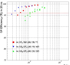
Since the time resolution of a triple-GEM detector operated with an Ar/CO2 (70/30) gas
mixture is about 10 ns (r.m.s.), an intense R&D activity on GEM detectors was required. The use of fastCF4 and isobutane based gas mixtures, together with an optimization of the
geometry and the electric fields of the detector, has allowed to improve the time resolution of the single detector down to 5 ns (r.m.s.), largely fulfilling the requirements of the experiment (σt≤ 3 ns is achieved by two logically OR-ed detector layers, as required in the LHCb muon
stations).
The final design of the detector has taken into account the tight space constraints around the beam pipe. We defined detailed construction procedures as well as severe quality controls for the production of 12 fully instrumented detectors required to cover the ∼ 1 m2 area of M1R1, plus 6 additional spare detectors.
The performance of one of such detectors, fully integrated with front-end electronics and all the other components, has been measured in a recent test at the SPS beam at CERN, where the LHCb running condition has been simulated by means of a similar bunch crossing time structure and the adoption of the official LHCb DAQ chain. The results largely fulfilled the experiment requirements and gave us useful informations for the future commissioning phase.
In addition we have demonstrated that the detector is robust from the point of view of dis-charges as well as ageing processes, and can tolerate the radiation dose foreseen in 10 years of operation in the region M1R1 of the LHCb experiment.
All the detectors are now at CERN, ready for the installation on the M1 station, foreseen for the first months of 2008.
The charm production at the LHCb experiment is even greater than the beauty production, thanks to the about seven times higher expected cross section (3.5 mb) with respect to the
beauty cross section (0.5 mb). Recent works demonstrated some interest for rare decays in
the charm sector, that can gives complementary information with respect to the K or B–
mesons physics and constrain the parameters of several extension of the Standard Model. In this framework, the results of a preliminary study of the rareD0 → µ+µ−decay at LHCb
experiment is presented in the second part of the thesis. Using the simulation and the analysis software realized for the experiment, a selection algorithm has been written, obtaining a first
estimation of the upper limit on the branching ratio achievable at LHCb that is about two order of magnitude lower than the current one.
Chapter 1
The LHCb experiment in the actual
physics scenario
LHCb [1] is the experiment at the Large Hadron Collider [2] dedicated to physics studies in the B-mesons system.
Although the Standard Model well describes the observed CP-violation processes in particle physics with the Cabibbo-Kobayashi-Maskawa mechanism, contributions from new physics beyond the Standard Model can change the expectations of CP-violation phases and rare decay branching fractions; cosmological problems such as the dominance of matter with re-spect to antimatter in the universe are still open and the level of CP-violation that can be generated by the Standard Model weak interaction is not enough to explain that.
LHCb has been designed for high precision measurements of CP-violation phenomena that will extend the results obtained at the B factories and Tevatron, over-constraining the unitary triangle. Moreover the search of rare or even Standard Model forbidden decays can address the physics community in the definition of New Physics models.
In this chapter, after an introductory section on the Large Hadron Collider project, the LHCb experiment will be described in its general layout, detectors, physics programme and ex-pected performance.
Chapter 1. The LHCb experiment in the actual physics scenario
1.1
The LHC project
The installation of the Large Hadron Collider (LHC) at CERN has been completed and the first proton-proton collisions will take place in 2008. The collider will gradually reach the center of mass energy of 14 TeV and the design luminosity of 1034 cm−2s−1, allowing to
probe the TeV-scale physics with a high statistics of events.
The project benefits from the existing LEP infrastructure, namely the 27 km long circular underground tunnel and its versatile and well-know accelerator injection complex.
The proton beams are accelerated in a linear accelerator (Linac) up to 50 MeV. Then two circular accelerators boost them to 1.4 GeV, in the Proton Synchrotron Booster (PSB), and to 25 GeV, in the Proton Synchrotron (PS), before entering in the Super Proton Synchrotron (SPS). There they reach the energy of 450 GeV and enter the LHC through two tunnels (Fig. 1.1). The main design parameters of the LHC machine is reported in Tab. 1.1 [2].
Figure 1.1: The LHC complex.
The basic layout of the machine is similar to the LEP, with eight straight sections approxi-mately 538 m long, available for experimental insertions or utilities. Four of these sections have the beam crossing from one ring to the other and are therefore dedicated to experimental sites, with two of them also hosting the injection system. Two insertions contain collimation systems using only classical robust magnets (betatron and momentum cleaning). One
inser-1.1 The LHC project
Machine circumference 26659 m
Beam energy 7 TeV
Luminosity 1034cm−2s−1
Luminosity lifetime 10 h Number of bunches 2835 Particle per bunch 1011
Bunch spacing 25 ns
Energy loss per turn 6.7 keV Crossing angle 300µrad
r.m.s. IP beam radius 16µm
r.m.s. IP beam length 5.3 cm
Dipole field 8.4 T
Table 1.1: The LHC machine parameters [2].
tion contain the RF system and the last straight section contain the beam dump insertion to remove the beam safely from the collider at the end of a physics run, when the luminosity has degraded.
The choice for a proton accelerator was driven by the fact that the losses by synchrotron ra-diation for electrons of the same energy are prohibitive, as illustrated by LEP run II. Indeed, the beam energy was forced to the limit of ≃ 104 GeV (intermittent) despite of a full use of superconducting technology. The huge RF power was then consumed just to compensate for the losses.
Two identical proton beams have been chosen to satisfy the high luminosity requirement. An antiproton beam as Tevatron collider would have simplified the technical conception but the low efficiency in antiproton production wouldn’t allow to achieve the required luminosity. As a consequence and in order to manage with the room in the existing tunnel, the magnet configuration is unusual as shown in Fig. 1.2. Two coil assemblies, surrounding the two beam pipes, are enclosed in the same iron yoke and cryostat. Given the radius of curvature of the orbit, the required huge operation field of 8.4 Tesla can only be obtained at acceptable cost by cooling the magnets to 1.9 Kelvin. There will be about 1200 of such 14 m long dipole magnets in the main arcs (Fig. 1.3).
The synchrotron energy loss per turn amounts to 6.7 keV is negligible in terms of RF power load, but the emitted power of 3.7 kW has to be absorbed by the beam pipe, that works at
Chapter 1. The LHCb experiment in the actual physics scenario
cryogenic temperature, thus affecting the power required by the refrigeration system. An ad-ditional issue is the release of absorbed gas molecules, when the synchrotron light impinges on the beam pipe (hard UV photons), which increases the residual gas pressure. This shows how has been demanding the design of this new machine.
Figure 1.2: Cross section of a LHC dipole mag-net. The inner coil keeps the two separated beams in orbit by using a 8.4 TeV T field. The coil is encapsulated in a cryogenic system, keeping the magnet at temperature of 1.9 K.
Figure 1.3: Picture of the LHC dipole magnet during the machine assembly.
Five experiments will make use of LHC. The ATLAS and CMS experiments located in new caverns built at IP1 and IP5 are multi-purpose central detectors. Their main (but not unique task) is to find the Higgs boson, using the full LHC potential by running at the very high de-sign luminosityL = 1034cm−2s−1. The ALICE experiment at IP2 will study the quark-gluon plasma in dedicated runs for heavy ions (Pb-Pb) collisions. TOTEM is a very small detector studying very forward QCD processes at IP5. It will measure the total cross section at LHC, which is very important for the other experiments, for instance to measure absolute luminos-ity. Finally, the LHCb experiment in IP8, dedicated to b-quark physics, will be described in detail in the next sections.
1.2 The proton-proton interaction setup at LHCb
1.2
The proton-proton interaction setup at LHCb
Since its startup LHC will be a high-rate charm, beauty and top quark factory, as shown in Tab. 1.2. Cross sections are extrapolated from UA1, CDF and D0 [3] data, but they are affected by large uncertainties.
Total σtot= 100 mb
Inelastic σin= 80 mb
cc σcc= 3.5 mb
bb σbb= 500µb tt σtt= 0.8 nb
Table 1.2: Cross sections at LHC.
The total inelastic cross section defines the average number of inelastic pp-interactions per
bunch crossing:
< Npp >= L · σin
fLHC· fne
whereL is the integrated luminosity, fLHC is the 40 MHz bunch crossing frequency of the
LHC machine andfne= 0.744 is the fraction of non-empty bunches crossing1.
This number is∼ 23 at the maximal LHC luminosity (L = 1034cm−2s−1), but LHCb plans to
operate at a lower average luminosity of 2×1032cm−2s−1, in order to obtain∼ 0.37 average interactions per bunch-crossing (Fig. 1.4). The advantages of this precise strategy are events dominated by single pp-interactions easy to analyse and a reduced radiation damage of the
detectors. Moreover this luminosity should be achieved since the first physics run of LHC operation and can be kept constant while the luminosity at the other interaction points will be progressively increased to their design values, allowing the experiment to collect data under constant conditions.
Theσbbcross-section at 14 TeV is extrapolated to be in the range 175 – 950µb, depending on
the value of badly known parameters. It will be known more precisely after the start of LHC, and the value of 500µb is a mean assumed as reference by all LHC experiments. The
dom-inantbb production mechanism in pp collisions is the fusion of two or more gluons radiated
from the constituent quarks of the protons. This leads to an approximately flat distribution in rapidity and hence an angular distribution peaked at low polar angles. The directions of
Chapter 1. The LHCb experiment in the actual physics scenario
the two b hadrons are very correlated as shown in Fig. 1.5. The two peaks correspond tobb
pair flying together in the same direction of the beam axis. Thus for a dedicated b-physics experiment the coverage of low polar angles is one of the primary task.
Figure 1.4: Probability distribution of the number of interaction per bunch crossing as a function of the luminosity.
Figure 1.5: Polar angleθ of b and b hadron
1.3 The LHCb apparatus
1.3
The LHCb apparatus
The LHCb detector [1], [4] is a single-arm spectrometer. Its similarity with a fixed target experiment (e.g. HERA-B) is explained by the very forward peaked b-quark distribution at LHC, as discussed in previous section.
Its main features are:
• a precise particle identification to access a wide range of multi-particle final states; • a high resolution vertex detector to identify secondary vertices and to precisely measure
the proper-time;
• a fast and versatile trigger system to select the interesting events among the huge num-ber of minimum bias events (σbb/σin= 0.6%).
It will be located at IP8 in the pit that housed the Delphi experiment during the LEP era. To avoid any civil engineering the detector had to fit in the pre-existent cavern, which constraints the total length of the detector to 20 m and require for a displacement of the interaction point by 11 m.
The geometrical acceptance of the detector, as defined by the dimensions of the magnet, is 300 mrad in the horizontal plane (bending plane) and 250 mrad in the vertical plane.
With this acceptance and the expected performance, the LHCb could detect the decay of both b hadron for about 20% of the whole bb events produced in 4π. The B-hadrons have
an average momentum of 80 GeV/c, which corresponds to a mean decay length of about 7 mm, and are characterized by a decay vertex separated from the primary vertex, resulting in higher impact parameters of the decay products tracks.
The experimental apparatus is shown in Fig. 1.6 and consists of five main sub-detectors: • the vertex system;
• the tracking system;
• the ring cherenkov detectors;
• the electromagnetic and hadronic calorimeters; • the muon system.
Chapter 1. The LHCb experiment in the actual physics scenario
Figure 1.6: Cross section of the LHCb spectrometer.
1.3.1 The vertex detector system
The Vertex Locator (VELO) [5] provides precise informations about charged particles close to the interaction point. Its fine segmentation allows for a precise primary vertex reconstruc-tion and search for separated secondary vertices.
The detector is composed of 21 disk-shaped 300µm silicon sensors, divided in two halves,
with ar − φ segmentation geometry, and distributed over 1 m along the beam axis around the interaction point. They will be mounted perpendicular to that axis on Roman pots inside a vacuum tank and will be retracted from the beams during injection (Fig. 1.7).
As it surrounds the interaction region it also allows some knowledge about the backward side of the event, which helps disentangling multiple primary vertices. Two additional sta-tions, onlyr-segmented, in the backward region act as veto for multiple pp-interaction events
(pile-up veto).
The position resolution on the primary vertex is 40 µm in z and 8 µm in x and y. For
sec-ondary vertices it varies from 150 to 300µm (in z) depending on the number of tracks. This
corresponds to less than 40 fs resolution on the B proper time of flight.
1.3 The LHCb apparatus Interaction regionσ= 5.3cm 390 mra d 15 mrad 1 m 60 mrad cross section at y=0:
not required for LHCb acceptance coverage
x
z
Figure 1.7: Up: The VELO vacuum vessel with the silicon sensor, RF box, and wakefield guides and exit win-dow; Bottom: The station set-up. Grayed layers have been removed after the reoptimization of the detector [4]
Chapter 1. The LHCb experiment in the actual physics scenario
high impact parameter tracks and secondary vertices.
1.3.2 The RICH detectors
The two Ring-Imaging Cherenkov detectors [6] have the main task of an efficient separation of kaons from pions over the full momentum range accessible from LHCb.
For the K-π separation the benchmark is the distinction between the B → Kπ, B → ππ and
B → KK channels. The RICH achieves a K-π separation above 3σ for tracks in the range
1-150 GeV/c with an efficiency of∼ 90%. It also crucial to tag the flavor of the reconstructed B hadron using the kaon from theb → c → s decay chain of the other b-hadron.
The RICHs detect the ring images formed by Cherenkov photons around the particle travers-ing the detector. The photons are detected by cylindrical pixelated Hybrid photodiode (HPD) tubes. These detectors are sensitive to magnetic fields, which impose that RICH detectors must be designed studying the fringe field of the magnet and a shielding solution of the HPD. Because of this requirement and the request to cover a wide momentum range, a system con-sisting of two Ring Imaging Cherenkov has been designed.
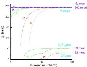
The first RICH (RICH-1) is placed upstream the magnet and uses the silica aerogel (refrac-tive index n=1.03) and C4F10 (n=1.0014) as radiators. It is designed for low momentum
(1-70 GeV/c) and high angle (30-300 mrad) tracks. A great effort has been done during the LHCb re-optimization [4] to obtain a compromise between a magnetic field slightly in-volving also the region between VELO and TT stations and the shielding of RICH-1 photon detectors.
The second RICH (RICH-2) is located downstream the magnet and the T1-T3 trackers, and uses only the CF4 (n=1.0005) as radiator. The RICH-2 covers high momentum (12-150
GeV/c) and low angle (15-120 mrad) tracks.
Fig. 1.8 shows the Cherenkov angle as a function of particle momentum for the radiators adopted in the the RICH system.
1.3 The LHCb apparatus
Figure 1.8: Cherenkov angle versus the particle momentum for the RICH radiators.
1.3.3 The magnet
The dipole magnet [7] is located close to the interaction point in order to keep it small, between the trigger tracker (TT) station and the remaining tracker stations (T1-T3) The field is oriented vertically which makes the track to bend in the horizontal x − z plane. It has a maximum intensity of 1.1 T and a total integrated magnetic field of 4 Tm for 10 m long tracks. Charged particle passing through the magnet will receive a pT kick of∼ 1 GeV/c.
Its aperture is 300 mrad in the bending plane and 250 mrad in the vertical one. The magnet is made of 50 tons of aluminum conducting wires and of 120 kt steel plate yoke. It dissipates about 4.2 MW.
To compensate a possible left-right asymmetries in the detector, the polarity of the magnet field can be reverse. This requirement and a detailed cost analysis have lead to the choice of a warm magnet rather than a superconducting magnet.
Chapter 1. The LHCb experiment in the actual physics scenario
Figure 1.9: Perspective view of the LHCb dipole magnet,
Figure 1.10: Magnetic field along the z axis.
1.3.4 The tracking system
The tracking system consists of four stations: the Trigger Tracker (TT), located downstream the RICH1 and in front of the entrance of the magnet, and the three stations (T1,T2, and T3), located between the magnet and the RICH2.
The Trigger Tracker [4] (TT) purpose is twofold.
In the High Lever Trigger, a first rough transverse momentum (20%–40%) estimation with-out using the other T stations is obtained by matching the tracks reconstructed in VELO with TT clusters, exploiting the fringe magnetic field present in the region (see Sec. 1.4).
In the off-line analysis it will be used to reconstruct the trajectories of long lived neutral par-ticles, which decay outside the VELO, and of low momentum particle, which are bent out of the acceptance of the experiment before reaching the tracking stations T1-T3.
The station is composed of four layers, two of them giving redundantly thex coordinate, and
the other two givingu and v stereo coordinates, rotated ± 5owith respect to x one.
The layers are covered entirely by 300µm thick silicon microstrip detectors with strip pitch
of 200µm and strip lengths of up to 33 cm. This allows to reach a spatial resolution of about
70µm.
1.3 The LHCb apparatus
tracks founded in the VELO to the hits in the TT station, in the calorimeters and in the muon detector. They also provide the seeding information for the RICH counters.
A mass resolution requirement of 10 MeV in high-multiplicity decays such asB0
s → DsK
translate to a momentum resolution requirement ofδp/p ≤ 0.4%.
To reduce particle occupancy, the T1-T3 stations are segmented in a Inner Tracker, located close to the beam pipe, and a Outer Tracker, which covers the remaining 98% of the area. Four detector layers are present in both region, with the samex and stereo coordinates layout
of TT.
The Inner Tracker [8] shares also the same technology of the Trigger Tracker, while the Outer Tracker [9] is made of straw tubes. These drift tubes have a 5 mm diameter and 75µm thick
walls. The Ar/CO2(70/30) drift gas mixture optimizes the spatial resolution (∼ 200 µm) and
the drift velocity, as well as the radiation hardness.
The total drift time, convolution of amplification and transmission time, is kept slightly be-low 50 ns. Requiring more computational time, the T1-T3 tracker information is used only in a later stage of High Level Trigger.
1.3.5 The Calorimeters system
The calorimeter system [10] identifies hadrons, electrons and photons and measures their energy and position. The information is used in the Level-0 trigger decision.
The detector design is a compromise between a small number of read-out channels and low occupancy, that results in a reasonable energy and position resolution.
It is placed downstream the RICH-2 and the first muon station (M1) and consists of an electromagnetic and a hadronic calorimeter (Fig. 1.11).
The electromagnetic calorimeter (ECAL) detects electrons and photons. It is a sampling calorimeter with lead as absorber material (25 X0 total radiation length). It is segmented in
three different granularity zones in order to optimize for theπ0reconstruction.
A Preshower is present in front of ECAL, consisting of 15 mm of lead sandwiched between two almost identical plane of rectangular scintillator pads (SPD and PS, each 15 mm thick, i.e. ∼ 2.5 X0). It allows the separation of photons and electrons showers induced in the
ECAL on the basis of the different topology and it is used as a trigger veto in case of events with a too high charged tracks multiplicity.
Chapter 1. The LHCb experiment in the actual physics scenario
Figure 1.11: Pictures of electromagnetic (left) and hadronic (right) calorimeter during the installation.
The energy resolution of the ECAL is:
σ(E)
E =
10%
pE/GeV ⊕ 1.5%
The hadronic calorimeter (HCAL), allowing hadrons (π±, K±, K0
L, p, n, Λ) detection via
inelastic interactions with its passive material, is made of 16 mm thick iron and 4 mm thick scintillating tiles, parallel to the beam. The light is collected at the end of the tile by wave-length shifting fibers (WLS).
The energy resolution of the HCAL is:
σ(E)
E =
80%
pE/GeV ⊕ 5%
1.3.6 The Muon system
The Muon system [11] identifies muons as the only penetrating charged particle able to pass through the whole calorimeters system. As high pT muons are mainly produced in B decays,
the muon detector is an essential component of the Level-0 trigger. It also used in the muon identification which is a basic ingredient of the search for rare semileptonic decays.
1.4 The LHCb trigger
1.4
The LHCb trigger
The trigger is a crucial component of the LHCb experiment and most sub-detectors features are motivated by trigger considerations. The high interaction rate, the low b cross-section compared to the total cross-section and the high multiplicity of the events make the efficient selection of interesting B-decays the major challenge.
At the LHCb nominal luminosity of L =2×1032cm−2s−1 a 10 MHz effective visible
colli-sions rate is expected, with a 25 ns bunch-crossing time structure. Given the ratio between total inelastic and bb cross-section, the bb pairs production rate can be around 100kHz, but
the B-mesons decays relevant for physics analysis have very small branching ratio (10−3–
10−9), so that the useful rate for physics analysis is only few tens of Hz. Taking into account
also calibration and control channels, the trigger must efficiently select events up to fill the maximum 2 kHz bandwidth capacity of the disk.
The trigger scheme has been revised since the Trigger TDR [12] and the new layout is shown in Fig. 1.12. The Level-0 Trigger is mostly unchanged in the logic as well as in the implemen-tation on hardware custom electronics; on the other hand the Level-1 Trigger is not longer required thanks to the great effort on all sub-detectors for a 1 MHz complete readout [13], and its logic is now part of the High Level Trigger, which has been largely reviewed [14].
Figure 1.12: The LHCb trigger scheme. The Level-0 trigger uses information from muon detectors, calorime-ters and pile-up VETO to reduce the event rate to 1 MHz. The HLT uses the information from all sub-detectors to write on disk only 2 kHz of events.
Chapter 1. The LHCb experiment in the actual physics scenario
1.4.1 The Level-0 trigger
The main task of L0 trigger is to reduce the event rate to 1 MHz, at which the complete LHCb readout is possible.
It has accomplished by looking for high transverse momentum muons, or high transverse energy deposits in calorimeters for photons, electrons and hadrons, exploiting the large B mass with respect to the other charmed or lighter mesons.
The Pile-Up system, consisting of two VELO disks in the region backward of the interaction point, identifies multiple interactions and it is used to suppress events with multiple vertices hard to analyse. For the same reason, events are discarded in the case of a high charged tracks multiplicity detected in the SPD Preshower.
The Pile-Up and SPD Vetoes information, together with the highestpT photons, electrons,
hadrons and the two highestpT muons, are passed to the L0 decision unit, which forms the
final decision.
The fully synchronous L0 trigger has a fixed latency of 4µs and is implemented on custom
boards. Even if it is a hardware trigger, a tuning of the cuts is possible and efficiencies of 60%, 50% and 90% are expected for events with hadrons, electrons and muons respectively. The optimization of the cuts for the precise measurements ofCP-violating parameters leads a bandwidth of 70% for the hadron trigger, 28% for the electron and photon trigger, 16% for the muon trigger.
1.4.2 The High Level Trigger
If a L0 Decision is issued, the full detector data is read out and sent to an about 1800 CPU node Event Filter Farm (EFF), which implements the High Level Trigger (HLT) algorithm. Even with the full detector data accessible, the HLT aims to first reject the bulk of the events using only part of the available information.
It is composed by the so called alleys 1.13, where each alley address one the L0 trigger type (muonic, hadronic, and electromagnetic calorimeter) and enriches theb content of the events
by refining momentum measurement and adding impact parameter information.
Most of the L0 triggers are of only one type, and only 15% of the triggers traverse more than one alley.
1.4 The LHCb trigger
Figure 1.13: The HLT alleys structure. Only events passing at least one of the alleys are processed by inclusive and exclusive selections.
resonances are reconstructed, and the exclusive selections, which will reproduce the offline selections using looser cuts. An event is finally written on disk if it pass at least one of the inclusive or the exclusive selections.
The HLT is still evolving so the cuts and the bandwidth of each stream is not yet well de-fined, but Table 1.3 can give an idea of the proposed bandwidth share and the purpose of each stream.
Dimuon 600 Hz Time unbiased dimuons with a mass above 2.5 GeV. These events are used to measure the uncertainty on lifetime measurements.
Inclusive B 900 Hz Events with one high PT and IP muon, or a moderate PT and high-IP muon making a vertex with a high PT and IP hadron. Used for systematic studies of the trigger efficiency and for data mining. Because of the muon, this sample is highly tagging-enriched.
Exclusive B 200 Hz The core physics stream with exclusively reconstructed decays. It also in-cludes sidebands and control channels.
Inclusive 300 Hz PID-blind D* events with D0->hh and no D0 mass cut. Allows to measure the PID efficiency and mis-ID rate. Can also be used for CP measurements in D decays.
Chapter 1. The LHCb experiment in the actual physics scenario
1.5
B-physics performances and sensitivity at LHC experiments
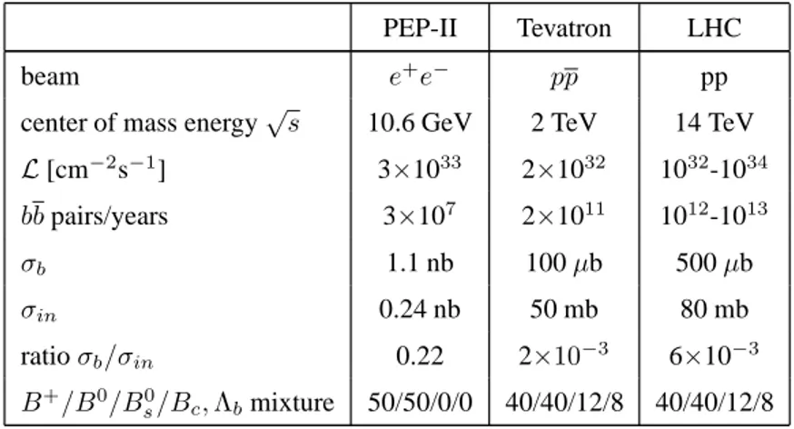
In comparison with the other accelerators that are in operation, LHC will be the most copious source of B mesons due to the highbb cross section as well as the high luminosity. Tab. 1.4
summarizes the features of the different colliders together with the B production.
PEP-II Tevatron LHC
beam e+e− pp pp
center of mass energy√s 10.6 GeV 2 TeV 14 TeV
L [cm−2s−1] 3×1033 2×1032 1032-1034 bb pairs/years 3×10⁷ 2×10¹¹ 1012-1013 σb 1.1 nb 100µb 500µb σin 0.24 nb 50 mb 80 mb ratioσb/σin 0.22 2×10⁻³ 6×10⁻³ B+/B0/B0 s/Bc, Λbmixture 50/50/0/0 40/40/12/8 40/40/12/8
Table 1.4: Features of the different colliders compared to the LHC machine. The B physics is also reported.
In general, the advantage of the experiments one+e− machine is the better signal to
back-ground ratio (∼ 0.22), but the statistics is limited (107 bb/years) with respect to a hadron
machine. Furthermore at Υ(4s) center of mass energy only the two lightest B-mesons, Bu
and Bdin equal proportion, are produced, while at LHC a variety of b-hadrons will be
pro-duced: Bu (40%), Bd(10%), Bs(10%) and Bc/b baryons (10%).
Physical observables related toCP violation [15] in the Bd0 system has been measured with a very high accuracy in the asymmetrice+e− B factories (BABAR experiment at SLAC and
BELLE experiment at KEK). From the decayB0 → ()K0, BaBar and Belle have measured
the angleβ, sin2β = 0.678 ± 0.026 [16], with a high precision and in excellent agreement with the indirect measurement ofVub/Vcband∆mdfrom semi-leptonic B0decays, andB −B
oscillation.
On the other hand, the measurements of the anglesα, coming from B0 → ππ, B0 → πρ
andB0 → ρρ decays, and γ, coming from B+ → D0K+, are limited by the low statistics.
Actually the measurements of these angle from the UTFit [17] are: sin2α = -0.047 ± 0.152 andγ = (66.7 ± 6.4)o.
In Tab. 1.5 the current experimental results on the B physics are summarized as reported in the UTFit collaboration homepage [17], while in Fig. 1.14 the status on the Unitary Triangle.
1.5 B-physics performances and sensitivity at LHC experiments
Channel Physical observable Measurement (@95% C.L.) Experiment
B → J/ψK0 s sin2β 0.690± 0.023 BaBar/Belle B → π+π− sin2α -0.047± 0.152 BaBar/Belle B → DK γ (66.7± 6.4)o BaBar/Belle B0 → D0π, Dρ 2β + γ (111 ± 13)o BaBar/Belle B0 s− B 0 soscillation ∆ms 17.7± 0.1 ps−1 CDF/D0/LEP/SLD
Table 1.5: Current results on the B physics taken from the UTFIT homepage [17].
ρ -1 -0.5 0 0.5 1 η -1 -0.5 0 0.5 1 γ β α ) γ + β sin(2 s m ∆ d m ∆ ∆md K ε cb V ub V ρ -1 -0.5 0 0.5 1 η -1 -0.5 0 0.5 1
Figure 1.14: Allowed regions for (ρ-η). The closed contours at 95% probability are shown. The full lines
correspond to 95% probability regions for the constraints, given by the measurements of|Vub|/|Vcb|, ǫK, ∆md,
∆md/∆ms,α, β, γ, ∆Γd/Γd, ∆Γs/Γs,AdSLand the dimuon asymmetry from D0 [17].
At the LHC energy, the high number ofBs-Bspairs per years (∼ 1011) will enable to
mea-sure theγ and δγ angles and the triangle side opposite to γ angle (corresponding to |Vtd/Vcb|)
with a very high accuracy. Moreover, the physics potential ofB0
s and the relative rare decays,
which are absent at the tree level in the Standard Model (SM), will provide, in addition to the fulfillment of the studies ofCP violation, a very fertile testing ground for the SM picture of flavour physics as well as interesting probes for new physics.
Chapter 1. The LHCb experiment in the actual physics scenario
1.5.1 B-physics at LHCb, ATLAS and CMS experiments
At the LHC, B-physics will be studied with two general purpose ATLAS [18] and CMS [19] detectors, and the dedicated LHCb experiment (Tab. 1.6). ATLAS and CMS are designed for high luminosity running and provide hermetic coverage, which is essential for Higgs and SUSY discover, while LHCb have a detector geometry optimized for the requirements of the B-physics: as explained in Sec. 1.2, at the LHC energy, theb − b pairs are preferentially emitted under a small angle relative to the beam direction.
LHCb ATLAS/CMS
Detector configuration Single-arm forward Central detector Running luminosity [cm−2s−1] 2×1032 3×1034
pseudo-rapidity range (η) 1.9÷ 4.9 -2.5÷ 2.5
< interactions/crossing > ∼0.4 (∼ 30% single int.) ∼ 23 bb pairs/years (integrated in the η range) 1012 5×10¹³
Table 1.6: Comparison of the LHC experiment parameters.
Fig. 1.15 shows the pseudo-rapidity as well as the transverse momentum coverage of the detectors. LHCb can measure pT below 2 GeV/c and thereby, despite its small angular
coverage 1.9 < η < 4.9, has access to a visible b-cross section of about 230 µb. On the
contrary, ATLAS and CMS, covering the central range |η| < 2.5 and operating at higher
luminosity, have to raise the pT-threshold to values around 10 GeV/c in order to achieve
sufficient background rejection.
In addition, the presence of RICH detectors in LHCb allows to study with an high efficiency pure hadronic decays due to the high K-π separation (3σ) in a wide momentum range (1-150
GeV/c). On the contrary, ATLAS and CMS have no a dedicated hadronic particle identifica-tion detectors. For example, the Transiidentifica-tion Radiaidentifica-tion Detector (TRD) of ATLAS provides a dE/dx measurement giving a K/π separation of about 0.8σ, precluding most of the hadronic
B decays.
Among the rare B decays, the B0
s → µ+µ− is the most interesting, since the current limit
(5.8×10⁻⁸, measured by CDF [20]) is approaching the foreseen SM branching ratio (about
3.5×10⁻⁹[21]).
With its excellent muon detection capability, CMS can observe an estimated 26 signal events with 6.4 events background for 100 f b−1 of running, i.e. the first year of full luminosity
1.5 B-physics performances and sensitivity at LHC experiments
Figure 1.15: Phase space coverage of the LHC experiments for B-physics.
operation. On the other hand, also LHCb can arrive as well to the observation of this channel in the scenario of the SM, using its lower design luminosity, that will be reached since the first year of operation.
In Tab. 1.7 the sensitivity of LHCb and ATLAS/CMS are summarized for a selection of benchmark channels for one years of running, corresponding to an integrated luminosity of 2 fb−1and 100 fb−1respectively.
Channel Physics Observable LHCb ATLAS CMS
B0 d → J/ψK 0 s β 0.3÷0.5o 0.6o 0.7o B0 d → ππ α 2÷10o 3o 5o B0 d → ρπ α 5÷15o - -B0 d → D0K γ 4÷18o - -B0 d → D∗π,3π 2β+γ < 7o - -B0 s → J/ψΦ δγ 0.6o 0.9o -B0 s → DsK γ − 2δγ 3÷16o - -B0 s → µ+µ− Rare decay 4.4σ S.M. 4.3σ S.M. 10σ S.M.
Table 1.7: Performance of the LHC experiments in a selection of benchmark channels for one year of operation at the relative luminosity. The quoted numbers are the errors on parameter in question. A dash for an entry means that no significant measurement can be made [22].
Chapter 1. The LHCb experiment in the actual physics scenario
In chapter 5, where the possibility of the search of the rareD0 → µ+µ−decay is investigated,
Chapter 2
The Muon System
Muon triggering and off-line muon identification are fundamental requirements of the LHCb experiment. Muons are present in the final states of manyCP-sensitive B decays, in partic-ular the two “gold-plated” decays, B0
d →J/ψ(µ+µ−)K0s andBs0 →J/ψ(µ+µ−)Φ. Moreover,
muons from semi-leptonic b decays provide a tag of the initial state flavour of neutral B
mesons. In addition, the study of rare B decays such as the Flavour Changing Neutral Cur-rent decay, B0s → µ+µ−may reveal new physics beyond the Standard Model.
The LHCb muon detector uses the penetrative power of muons to provide a robust muon trigger. The heavy-flavour content of triggered events is enhanced by requiring the candi-date muons to have high transverse momentum,pT. The same unique properties are utilized
off-line, to accurately identify muons reconstructed in the tracking system and to provide a powerful B-meson flavour tag.
2.1
Physics requirements
The main requirement for the muon detector is to provide a high-pT muon trigger at the
earliest trigger level (Level-0). The effective LHCb Level-0 input rate is about 10 MHz on average atL = 2×1032cm−2s−1, assuming an inelasticpp cross-section of 80 mb. This input
rate must be reduced to 1 MHz within a latency of 4.0µs, while retaining good efficiency for
events containing interesting B decays.
The muon trigger must provide for about 20% of the total bandwidth. It is based on a fast muon track reconstruction and pT measurement with a resolution of∼ 20%. To
unambigu-Chapter 2. The Muon System
ously identify the bunch crossing, the choice of detector technology must be driven by a high time resolution as well as a high detection efficiency.
The muon system must also provide offline muon identification. Muons reconstructed in the high precision tracking detectors with momenta down to 3 GeV/c must be correctly identi-fied with an efficiency of above 90%, while keeping the pion misidentification probability below 1%. Efficient muon identification with low contamination is required both for tagging and for the clean reconstruction of muonic final state B decays.
2.2
General detector structure
The muon detector consists of five muon tracking stations placed along the beam axis. The first station (M1) is placed in front of the calorimeter Preshower, at 12.1 m from the in-teraction point, and is important for the trigger transverse-momentum measurement because the hit in this station is not affected by the multiple scattering of calorimetric system mate-rial. On the other hand, the M1 station has as additional requirement a radiation length of the detector materials below 10% of X0 on average, in order to not degrade the calorimeters
measurements.
The remaining four stations, with an iron shield between them, are at mean positions of 15.2 m (M2), 16.4 m (M3), 17.6 m (M4) and 18.8 m (M5). The three iron filters and the elec-tromagnetic and hadronic calorimeters correspond to 20 nuclear interaction lengths, and to traverse the 5 stations a muon must have a minimum momentum of 8 GeV/c.
The positions of the muon stations can be seen in Fig. 2.1, which shows a side view.
The chambers within the filter are allocated in about 40 cm of space and are separated by three shields of 80 cm thickness. The angular acceptances of the muon system is from 20 to 306 mrad in the bending plane and from 16 to 256 mrad in the non-bending plane, similar to the one of the tracking system. This provides a geometrical acceptance of about 20 % of muons from b decays with respect to the full solid angle. The total detector area is about 435 m2.
2.2 General detector structure
Chapter 2. The Muon System
2.3
The station layout
The Muon system provides a digital information about thex − y spatial coordinates of the muon tracks. The spatial resolution is given by the dimension of a logical pad, whose struc-ture across the detector represents the logical layout. The logical layout describes thex and y granularity in each region of each muon station, as seen by the muon trigger and off-line
reconstruction.
Since the polar angle and momentum of particles are correlated, high momentum tracks tend to be closer to the beam axis. Therefore multiple scattering in the absorber increases with the distance from the beam axis, limiting the spatial resolution of the detector. The granu-larity of the logical pads varies accordingly and have been chosen such that its contribution to resolution the trigger pT measurements is approximately equal to the multiple-scattering
contribution. The various contributions to thepT resolution are shown in Fig. 2.2.
Figure 2.2: Contributions to the muon trigger resolution of transverse momentum measurement as a function of the muon momentum, averaged over the full acceptance. ThepT resolution is defined as|precT − ptrueT |/ptrueT ,
and is shown for muons from semi-leptonic b decay having a reconstructedpT close to the trigger threshold,
between 1 and 2 GeV/c.
Given the different granularity and the large variation in particle flux from the central part, close to the beam axis, to the detector border, each station is subdivided into four regions
2.3 The station layout
with different logical pad dimensions. Regions and pad sizes scale by a factor two from one region to the next.
In they plane all the tracks appear to straight lines, as they are not bent by the magnet, thus
the required granularity is broader, and the logical pads are wide, as appear in Fig. 2.3. The
y dimension is determined principally by the rejection of background events which do not
point to the interaction region.
Otherwise the x dimensions of the logical pads are determined primarily by the required
precision to obtain a good muonpT resolution for the Level-0 trigger.
The resultingy/x aspect ratios are 2.5 in station M1 and 5 for stations M2 and M3. Stations
M4 and M5, which are used to confirm the presence of penetrating muons, have aspect ratios of 1.25. The total number of logical pads in the muon system is about 55 thousand.
Figure 2.3: Front view of one quadrant of muon station 2, showing the dimensions of the regions. Inside each region is shown a sector, defined by the size of the horizontal and vertical strips. The intersection of the horizontal and vertical strips, corresponding to the logical channels, are logical pads. The region and channel dimensions scale by a factor two from one region to the next.
Chapter 2. The Muon System
occupancy and capacitance considerations, according to the detector technology. The Muon system has been designed in a flexible way, such that the required logical layout can be achieved in several ways and is independent from the type of detector used (Fig. 2.4).
Figure 2.4: Logical pads and physical pads in Region 4 (top) and Region 2 (bottom) for Stations M4 and M5. In the former case thex dimension is that of 4 chamber strips and the y dimension is the same of the chamber
itself. In the latter case more granularity is required and bothx and y have half dimensions.
2.4
The level-0 muon trigger
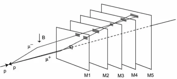
The muon level-0 trigger (L0) looks for muon tracks with a large transverse momentum, requiring information from all five muon stations. The track finding is performed on the logical pad layout and the scheme shown in Fig. 2.5 is adopted. Starting from each hit in M3, called track seed, a straight-line is extrapolated towards the interaction point and is extended backward up to the station M5. In M2, M4 and M5, hits are looked for a regions, the so-called field of interest (FOI), centered in the intersections between the station and the straight-line. If at least one hit is found in M2, M4, M5 FOIs, the track is flagged as a muon candidate. A second straight-line passing through the hit in M2 and the track seed, is extrapolated to M1 to define the center of the FOI. If at least one hit is found in the M1 FOI, the track is definitely flagged as a muon.
Since the logical layout is projective, there is a one-to-one mapping from pads in M3 to pads in M2, M4 and M5. There is also a one-to-one mapping from pairs of pads in M2 and M3 to pads in M1. This allows the track-finding algorithm to be implemented using only logical operations.
2.4 The level-0 muon trigger
determined from the track hits in M1 and M2. Because of the distance between M1 and M2 (3.1 m) and the high granularity of M1, a good resolution of thepT measurement,∼ 20%, is
obtained. The momentum measurement assumes a particle from the interaction point and a single kick from the magnet.
Figure 2.5: Track finding by the muon trigger. In the example shown,µ+andµ−cross the same pad in M3.
The highlighted in the various station represent the field of interest where the hits are searched.
A first consequence of this scheme is that the L0 trigger efficiency is highly affected by the single station efficiency, as follows:
ǫtrigger = (ǫstation)5
whereǫstationis defined in a fixed time window of 20 ns because the hit must be also assigned
to the correct bunch crossing, which are separated by 25 ns.
In order to improve the single station efficiency, providing also some redundancy, the M2-M5 stations consist of four independent detector layers, and the hits of the station is the logical OR of the hits of all layers. Only two detector layers are foreseen for the M1 station in order to reduce the material budget in front of the calorimeters.
The efficiency for M2-M5 stations must be> 99%, and > 96% for the M1 station, due to
the presence of only two detector layers.
As result of such stations efficiencies, the L0 muon trigger efficiency comes out to be higher than 92%.
Chapter 2. The Muon System
2.4.1 Background environment
The high hit rates in the chamber affect the muon transverse momentum resolution due to incorrect hit association. Four classes of backgrounds relevant to the B→ µX detection can be distinguished:
1. Decays in flight muons: The large number of π/K mesons produced in the p − p colli-sions contribute mainly to the background in the muon system through decays in flight. Such decay muons form the main background for the L0 muon trigger.
2. Shower particles: Photons from π0 decays can interact in the area around the beam
pipe and generate electromagnetic showers penetrating into the muon system. Hadrons emerging from the primary collision can interact later in the calorimeters and contribute to the background in the muon system through shower muons or hadron punch-through. 3. Low-energy background: Another important background is associated with low-energy neutrons produced in hadronic cascades in the calorimeters, the muon shield or in ac-celerator components. They create low-energy radiative electrons via nuclear n-γ
pro-cesses and subsequent Compton-scattering or via the photo-electric effect in the detec-tor material of the muon chambers. The photons have a probability of a few per mil to generate detectable electrons via these effects, which are in general only affecting a single detector layer. Moreover, the hits due to the low energy background can occur delayed up to a few 100 ms after the primary collision.
4. Beam halo muons: The charged-particle flux associated with the beam halo in the ac-celerator tunnel contains muons of a rather wide energy spectrum and the largest flux at small radii. In particular those halo muons traversing the detector in the same direction as particles from the interaction point can cause a L0 muon trigger.
Background caused by real muons traversing the detector is well simulated with the available Monte Carlo packages [23], [24]. An estimate for the rate in the various regions of the muon system has been obtained from a detailed study [25], [26], whose results are summarized in Tab. 2.1.
The nominal rates are calculated for a luminosity of L = 5×1032 cm−2 s−1. The maximal
rates are then obtained applying a safety factor of 5 in the stations M2–M5 and a safety factor of 2 in the station M1, which is positioned in front of the calorimeters and therefore is less affected by the uncertainties in the showering processes in the absorber material. The
2.5 Muon system technologies
Station 1 Station 2 Station 3 Station 4 Station 5 Region 1 230 kHz/cm2 7.5 kHz/cm2 2 kHz/cm2 2.3 kHz/cm2 880 kHz/cm2 460 kHz/cm2 37.5 kHz/cm2 10 kHz/cm2 6.5 kHz/cm2 4.4 kHz/cm2 Region 2 93 kHz/cm2 5.3 kHz/cm2 650 Hz/cm2 430 Hz/cm2 350 Hz/cm2 186 kHz/cm2 26.5 kHz/cm2 3.3 kHz/cm2 2.2 kHz/cm2 1.8 kHz/cm2 Region 3 40 kHz/cm2 1.3 kHz/cm2 200 Hz/cm2 150 Hz/cm2 130 Hz/cm2 80 kHz/cm2 6.5 kHz/cm2 1.0 kHz/cm2 750 Hz/cm2 650 Hz/cm2 Region 4 12.5 kHz/cm2 230 Hz/cm2 83 Hz/cm2 50 Hz/cm2 45 Hz/cm2 25 kHz/cm2 1.2 kHz/cm2 415 Hz/cm2 250 Hz/cm2 225 Hz/cm2
Table 2.1: Particle rates in the muon system.The first row gives the calculated rate at a luminosity of L = 5×1032cm−2s−1assuming a totalp − p cross-section of σ=102.4 mb; in the second row the rate includes the
safety factors.
rate rises from a few hundred Hz/cm2 in the outer regions of stations M4 and M5 to a few hundred Hz/cm2 in the innermost part of station M1.
2.5
Muon system technologies
High particle fluxes in the muon system impose stringent requirements on the instrumenta-tion. These requirements include the rate capability of the chambers and the robustness after long-term irradiation, that must be taken into account together with the required performance for the prefixed physics goal. The technology choice has been determined by the following parameters:
1. Rate capability: The selected technologies must tolerate the expected particle rate with-out efficiency losses;
2. Ageing robustness: The detector must tolerate, without damages or performance losses, the integrated charge accumulated in 10 years of operation;
3. Time resolution: The muon system must provide unambiguous bunch crossing identi-fication with high efficiency. The requirement is at least 99% efficiency within 20 ns window for M2-M5 stations, and at least 96% for M1 station.
4. Spatial resolution: A good spatial resolution is required, especially in M1 and M2, in order to obtain an accuratepT evaluation (∼ 20%). Therefore it is important to reduce as
Chapter 2. The Muon System
much as possible the probability of having more than one pad fired by a crossing track. This effect is described as geometrical pad cluster size. Depending on the average crossing angle of the track, the pad size and the layer separation, the geometrical pad cluster size varies between 1.1 in the outer part and 1.2 to the inner part of the muon system;
Based on the above considerations, the ∼ 99% of the area of the Muon system will be equipped with Multi Wire Proportional Chamber (MWPC) [27]. The innermost region (R1) of the first station (M1), where a particle flux up to∼ 500 kHz/cm2 is expected, will be in-strumented with triple-GEM detectors (Gas Electron Multiplier) [28]. It should be stressed that the M1R1 region, of about∼ 0.6 m2area, will be crossed by about the 20% of the total triggered muons.
The technical specifications and the performances of the MWPC detectors are summarized in the following section, while the performances of a triple-GEM detector, the subject of my thesis, will be discussed in detail in the following two chapters.
2.5.1 MWPC detectors
The MWPC chambers for the station M2-M5 are composed by four symmetric gas gaps, each of them with a plane of anode wires in between of two cathode planes. The gap is 5 mm wide and the anode-cathode distance is 2.5 mm. The wires are made of gold-plated tungsten with a diameter of 30µm and a pitch of 2 mm. A schematic view is given in Fig. 2.6, while in
Tab. 2.2 are summarized the main parameters of the MWPC detectors.
2.5 Muon system technologies Parameter Design value
No. of gaps 4 Gap size 5 mm Anode-Cathode distance 2.5 mm Wire Diameter 30µm Wire pitch 2 mm Wire tension 70 g Gas mixture Ar/CO2/CF4
(40/50/10) Primary ionisation ≃ 10 e−/mm
Gas Gain ≃ 105
Threshold > 5 fC
Table 2.2: Main LHCb MWPC parameters.
Chambers are readout in different way, depending on their position in the muon system:
• In region R4 of all the five stations, the chambers have anode-wire readout through decoupling capacitors;
• In region R3 of all the five stations and in regions R1 and R2 of stations M4 and M5 cathode pads are readout;
• In regions R1 of stations M2 and M3 and in regions R2 of stations M1 – M3 a combined readout of wire and cathode pads is used.
Anode wires are grouped into vertical strips to measure x whereas the y coordinates are
pro-vided by the granularity of the horizontal cathode pads.
Wires are grouped in pads of 4 to 42 to match the required granularity, varying from 6 mm in region R1 of station M2 to 62 mm in region R2 of station M5. The Muon system requires 864 MWPC chambers, with≃ 2.5×10⁶wires and about 80,000 front-end channels.
Five centers are foreseen to produce the whole MWPC chambers: one in S.Petersburg’s Nu-clear Physics Institute (PNPI), three in Italy (Ferrara, Firenze and Laboratori Nazionali di Frascati) and one at CERN. These centers have been equipped with similar tools, which are automated in order to speed up the construction and to achieved the required mechanical precision and tolerance. The details of the MWPC construction is reported in Ref. [27].
Chapter 2. The Muon System
MWPC performances
An intensive programme of development work has been undertaken. Several MWPC proto-types have been constructed according to the different read-out requirement and the relative performances have been measured in various tests beam and in laboratory.
For completeness, I report some results obtained on the full size prototype with cathode-pad readout for Region 3 of Station 3 (M3R3). The chamber prototype have been built in the Laboratori Nazionali di Frascati with the final design, materials and construction procedure. The measurement have been performed at the T11 beam line at CERN PS with 3.6 GeV/c pions. In Fig. 2.7 is shown the efficiency in 20 ns window and the pad cluster size as function of the high voltages for a MWPC station. A wide working region, defined as the HV range between the onset of efficiency plateau (99%) and the HV at which the pad cluster size is under 1.2., of about∼ 200 Volt, is obtained for an electronics threshold of 7 fC.
Figure 2.7: Efficiency in 20 ns time window and in-time pad cluster size as a function of the high voltage (HV) for a MWPC station [29].
Global ageing tests have been performed at the ENEA-Casaccia in the Calliope gamma fa-cility with a60Co source. The test has been performed together with our full size triple-GEM detectors and it will be discussed in Sec. 4.5.
During this test the MWPC integrated∼ 500 mC/cm of wire equivalent to ∼ 5 years of op-eration at LHCb experiment [30].
2.6 Electronics
2.6
Electronics
The muon system front-end electronics (FEE) produces the digital output signals from de-tectors and transfer the information to the L0 muon trigger as quickly as possible [31]. The readout electronics chain comprises the following elements:
• CARDIAC boards directly on the chambers. The board is equipped with amplifier, shaper and discriminator chips called CARIOCA, and a DIALOG chip that combines the output signals of the CARIOCA to form logical channels;
• Intermediate (IM) boards placed on the side of the muon apparatus, to generate logical channels for those regions where this has not been possible on the chambers, because the logical channels are made of physical channels belonging to different chambers;
• Off-Detector Electronics (ODE) boards, also located on the side of the apparatus, where the data is synchronised and dispatched to the L0 trigger.
Such electronics must fulfill stringent requirements also in term of radiation hardness due to their location in the cavern. As an example, the specifications of CARIOCA chips [32] are summarized in Table 2.3.
Parameter Specification
Maximum signal rate 1 MHz
Maximum total dose 1 MRad
Peaking time ∼ 15 ns (Cdet=250 pF)
Input resistance < 50 Ω
Average pulse width < 50 ns (CARIOCA output)
ENC (r.m.s) for the positive amplifier 1880e−+45e−×C det(pF)
ENC (r.m.s) for the negative amplifier 2240e−+42e−×C det(pF)
Sensitivity ∼ 16 mV/fC
Chapter 3
The Gas Electron Multiplier
Fifty years ago, a radical innovation in the field of radiation detectors came from the inven-tion of the Multi-Wire Proporinven-tional Chamber (MWPC) by Charpak [33].
The good position accuracy and rate capability, the modularity and the possibility to in-strument large areas at relatively low cost, are all features that let the MWPC and their descendants, such as drift and time projection chambers, spread from high energy physics experiments up to astro-particle physics and medical applications.
Nevertheless, with the coming of new high luminosity colliders, the MWPC has shown some limitations concerning the capacity to tolerate the very high radiation fluxes.
To overcome these limitations, a new class of gas detectors, called micro-pattern gas
de-tectors (MPGD), has been developed since twenty years, and some of the technologies born
from that R&D are nowadays well-established, with several experiments exploiting them and many future experiments planning to do that.
This chapter will explain the passage from MWPC to MPGD in the next section, focusing then from Sec. 3.2 to Sec. 3.6 to the description of Gas Electron Multiplier technology, that is the subject of my thesis. Eventually, Sec. 3.7 to Sec. 3.8 will describe the R&D performed by our group on new fast gas mixture, in order to qualify this technology for the instrumen-tation of the region around the beam pipe of the LHCb-M1 sinstrumen-tation.
Chapter 3. The Gas Electron Multiplier
3.1
From Multiwire Proportional Chamber to Gas Electron Multiplier
Detectors
The limitation of rate capability in wire detectors is due to the low drift of ions from the anode wire towards the cathode. In fact, at high particle flux, the ion cloud generated around the wire creates a positive space charge that reduces the electric field near the wire, lead-ing to a rate-dependent gain drop. For a MWPC the maximum rate capability, dependlead-ing on the detector geometry (wire pitch, anode-cathode wire distance), is generally below 1 MHz/cm2[34].
An improvement in rate capabilities comes from the reduction of wire-cathode distance, in order to speed up ions collection. However, below 1 mm wire spacing and below 2 mm anode-cathode gap, the MWPC becomes difficult to operate because of electrostatic instabil-ities arising from the mechanical tolerances.
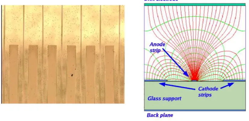
The first example of the micro-pattern detector was the Micro-Strip Gas Chamber (MSGC) introduced by Oed [35] in 1988 and extensively developed by other authors in the following years [36]. The new device improved the rate capability and the position accuracy by more than one order of magnitude. The detector geometry is shown in Fig. 3.1: the anode and the
Figure 3.1: Micro Strip Gas Chamber: left) picture of the anode and cathode strips; right) sketch of the detector.
cathode are thin metallic strips which are placed on an insulating support. The upper elec-trode, called drift elecelec-trode, is used to define the drift region. A further electrode behind the insulating support, the back-plane, can be segmented as orthogonal strips giving the second coordinate.
pro-3.1 From Multiwire Proportional Chamber to Gas Electron Multiplier Detectors
portional counter. The electrons, produced by the radiation crossing the detector in the drift region, move towards the anode strips where they are multiplied. The ions produced in the avalanche are mainly collected in the neighbouring cathode strips typically 100 µm distant
from the anode.
Standard photolithography technology allows to produce 0.3÷0.5 µm thick cathode and an-ode strips with 100µm of pitch. The manufacturing process is the same used for the
produc-tion of multi-layer printed boards.
Operating instabilities were observed in the early device due to the charging-up of the insu-lating support. In fact when high particle flux crosses the detector, a part of the multiplica-tion ions could be collected on the insulating support. This accumulated charge produces a change of the electric field between the strips changing the detector gain. This effect, which is rate dependent, could be reduced or eliminated using slightly conducting supports [37], and rate capability up to 100 MHz/cm2 could be achieved [38].
MSGCs appeared however rather susceptible to aging and discharge damages.
Long-term studies have shown a slow degradation of performances, attributed to the forma-tion of polymers in the avalanche. Anyway, with the proper choice of the components, as gas mixture and detector materials, a long-term survival up to collected charge above 100 mC per cm of strip equivalent to about ten years of operation at LHC has been demonstrated [39]. The appearance of destructive discharges appeared instead to be a more serious problem. In fact, a transition from avalanche to streamer, which is gas gain and ionization density de-pendent, could easily followed by a discharge due to the short distance of the electrodes. The discharge could heavily damage the strips increasing the dead channels population on long-term operation. This limitation is particular apparent in the new luminosity colliders, where among the particles to be detected, rare but heavily ionizing tracks (nuclear frag-ments, gamma and neutron conversions) are present. Thus a gain arrangement, that allows at the same time the detection of minimum ionization particles (m.i.p.) excluding the damage produced by the crossing of heavily ionizing particles, is very challenging [40].
Motivated by the above mentioned problems, a great effort has been made to find a more rugged alternative detector to the MSGC. In fact in the following years many of such detec-tors have been invented (Fig. 3.2): the microgap chamber (MGC) [41], the Microdot [42], the "Compteur `a Trous" (CAT) [43], the Micromesh gas chamber (MicroMeGas) [44], the
Micro-Groove [45] and the WELL [46] detectors.
![Figure 2.7: Efficiency in 20 ns time window and in-time pad cluster size as a function of the high voltage (HV) for a MWPC station [29].](https://thumb-eu.123doks.com/thumbv2/123dokorg/7609821.115175/44.918.285.552.510.759/figure-efficiency-window-cluster-function-voltage-mwpc-station.webp)
![Figure 3.11: Relative signal amplitude on the PCB as a function of the drift field [55].](https://thumb-eu.123doks.com/thumbv2/123dokorg/7609821.115175/58.918.288.548.110.296/figure-relative-signal-amplitude-pcb-function-drift-field.webp)
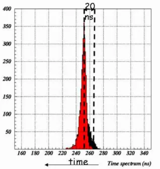
![Figure 3.28: The best time distribution for single detector obtained at PS beam facility of CERN [67]](https://thumb-eu.123doks.com/thumbv2/123dokorg/7609821.115175/80.918.262.575.325.657/figure-best-distribution-single-detector-obtained-facility-cern.webp)