Scuola di Dottorato in Ingegneria "Leonardo da Vinci"
Corso di Dottorato di Ricerca in
Ingegneria dell’Informazione
Tesi di Dottorato di Ricerca
Mixed-signal Integrated
Circuits Design and Validation
for Automotive Electronics
Applications
Tommaso Baldetti
Ph.D. Program in Information Engineering
Micro and nanoelectronic technologies, devices and systems
SSD ING-INF/01
Mixed-signal integrated circuits design
and validation for automotive
electronics applications
Thesis
Tommaso Baldetti
Year 2012
Tutors: Prof. Luca Fanucci . . . . Prof. Sergio Saponara . . . . Prof. Roberto Saletti . . . . Candidate: Tommaso Baldetti . . . .
Introduction xi 1 A glimpse on automotive electronics trends 1
1.1 Automotive electronics applications . . . 3
1.1.1 Powertrain and engine management . . . 3
1.1.2 Body electronics and security . . . 7
1.1.3 Infotainment . . . 12
1.2 Future challenges for automotive electronics . . . 14
2 High-level modeling of analog-mixed signal IPs 17 2.1 Introduction . . . 17
2.2 MEMS for optical applications . . . 18
2.2.1 Bulk micromachining . . . 20 2.2.2 Surface micromachining . . . 21 2.2.3 MOEMS applications . . . 21 2.3 Scanning micromirrors . . . 31 2.3.1 Electrostatic actuation . . . 34 2.3.2 Electromagnetic actuation . . . 36 2.3.3 Thermal actuation . . . 37
2.4 Nonlinearities Modeling in Resistive DACs . . . 38
2.4.1 Effect of a Linear Gradient . . . 38
2.4.2 Effect of Random Variations . . . 40
2.4.3 High-level Model Implementation . . . 42
2.5 Case study: 10 bit resistive string DAC design . . . 49
2.5.1 The µmirror/laser projection system . . . 49
3 Integrated voltage references 61 3.1 Bandgap references . . . 62
3.2 BGR1: pseudo regulated supply rail . . . 63
3.2.1 Bandgap core circuit . . . 68
3.2.2 Startup circuitry . . . 70
3.2.3 BGR layout design . . . 71
3.2.4 BGR characterization . . . 71
3.3 BGR 2: pre-regulation of bias current . . . 77
3.3.1 Bandgap core circuit . . . 78
3.3.2 Startup circuitry . . . 80
3.3.3 Service regulator . . . 81
3.3.4 BGR characterization . . . 82
3.3.5 Experimental results . . . 86
4 A flexible analog driver in CMOS 0.18 µm technology 89 4.1 Architecture description . . . 91
4.1.1 Slew rate boost circuitry . . . 95
4.1.2 Short circuit detection circuitry . . . 96
4.2 Fabrication and experimental results . . . 99
5 Efficient Test Environment 103 5.1 Mixed-signal verification . . . 104
5.2 VHDL-AMS simulation flow . . . 105
5.2.1 System verification flow . . . 105
5.2.2 VHDL-AMS modeling . . . 107
5.2.3 Automatic netlist extraction . . . 107
5.3 Environment upgrades . . . 109
5.3.1 Python script and text file . . . 109
5.3.2 Full Python environment . . . 110
5.4 Test case: 3D consumer gyro x axis gain calibration . . 113
List of acronyms 119
1.1 Some automotive electronics systems . . . 4
1.2 Future powertrain architecture block schematic . . . . 6
1.3 Power usage in passenger vehicles [9] . . . 6
1.4 Block schematic of main chassis/safety electronic systems 8 1.5 Inertial Measurement Units . . . 9
1.6 Electrical Power Steering system . . . 10
1.7 The three main areas of car infotainment systems [21] 13 1.8 Car infotainment system [source: Infineon] . . . 13
1.9 Cluster of sensors used to support ACC [source: Bosch] 14 1.10 Trend for automotive ECU/bus architecture. . . 15
2.1 Optical MEMS for fiber optic telecom market . . . 22
2.2 DMD overview . . . 25
2.3 A commercial MOEMS microspectrometer . . . 26
2.4 IR sensor and application . . . 27
2.5 A commercial barcode reader based on MOEMS devices 29 2.6 MOEMS based laser pico projectors . . . 30
2.7 Micromirror-based optical matrix switch . . . 33
2.8 Array of scanning micromirrors . . . 34
2.9 Some examples of comb drive actuators . . . 36
2.10 Micromirror with electromagnetic actuation . . . 37
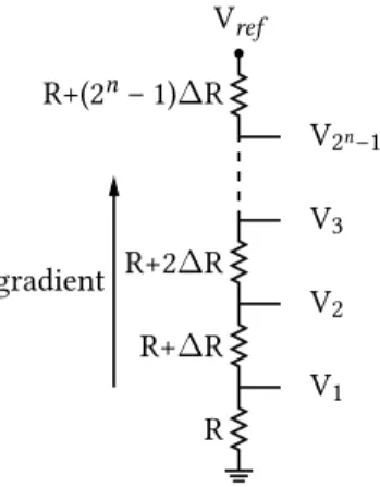
2.11 Some examples of electro-thermal actuated micromirrors 38 2.12 Schematic of a n bit resistive string converter . . . 39
2.13 INL due to a linear doping gradient . . . 40
2.15 Logic flow of the modelling. . . 43
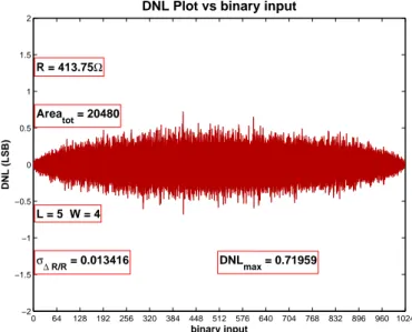
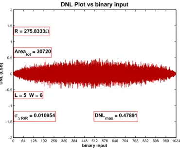
2.16 DNL plot with L = 5 µm, W = 4 µm, nr. of runs equal to 30. 45 2.17 INL plot with L = 5 µm, W = 4 µm, nr. of runs equal to 30. 46 2.18 DNL plot with L = 5 µm, W = 6 µm, nr. of runs equal to 30. 46 2.19 INL plot with L = 5 µm, W = 6 µm, nr. of runs equal to 30. 46 2.20 A dual-stage resistor string DAC architecture . . . 47
2.21 DNL plot with L = 10 µm, W = 2 µm, 10 runs. . . 48
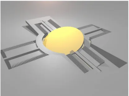
2.22 2-D scanning micromirror . . . 50
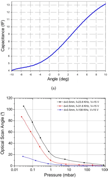
2.23 Results of the micromirror characterization . . . 53
2.24 DNL plot with L = 4 µm, W = 3 µm, nr. of runs equal to 30. 54 2.25 INL plot with L = 4 µm, W = 3 µm, nr. of runs equal to 30. 55 2.26 Schematic of a 16 resistors block . . . 55
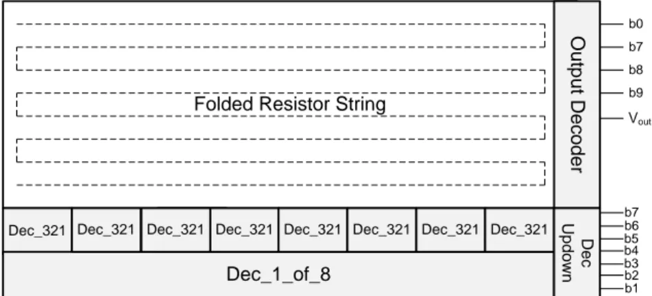
2.27 Block schematic of the designed D/A converter . . . 56
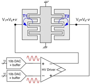
2.28 Buffer used as output stage of the resistive-string DAC 57 2.29 Actuation scheme of the micromirror driving circuit. . 58
2.30 Histogram from Monte Carlo simulation . . . 59
2.31 Layout of the D/A converter . . . 60
3.1 Bandgap principle schematic . . . 63
3.2 Architecture of the proposed BGR circuit . . . 64
3.3 Pseudo-regulator schematic . . . 65
3.4 Comparison between different mirror topologies . . . . 66
3.5 Current flowing in the two topologies . . . 67
3.6 Comparison between different circuit topologies . . . . 67
3.7 Voltage at node Vx for different topologies . . . 68
3.8 Bandgap core and startup schematic . . . 69
3.9 Whole circuit of the proposed BGR . . . 70
3.10 Layout of the BGR circuit. . . 72
3.11 Variation of VBG and VREGin 4-40V range . . . 73
3.12 Bandgap voltage over temperature variation. . . 74
3.13 Power-supply rejection of VBGvoltage . . . 75
3.14 Results of Monte Carlo analysis . . . 76
3.15 Complete schematic of HV bandgap reference . . . 79
3.16 Comparison between proposed topologies. . . 80
3.17 Performance comparison between topologies A and B (current). . . 81
3.18 Performance comparison between topologies A and B
(voltage). . . 82
3.19 Service regulator schematic. . . 83
3.20 Variation of VBGand Vout_reg vs. VBATT. . . 84
3.21 Behavior of VBGand Vout_reg vs. temperature sweep. . 85
3.22 Power-supply rejection of VBG voltage . . . 85
3.23 Measurement of VBGvalue over temperature . . . 87
3.24 Microphotograph of the fabricated ASIC. . . 88
4.1 Block schematic of the described architecture . . . 92
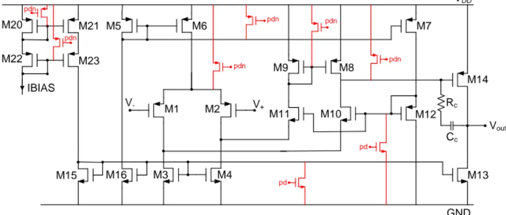
4.2 Complete schematic of the operational amplifier. . . 94
4.3 Effect of slew-rate enhancement. . . 95
4.4 Op-amp with slew-rate enhancement. . . 97
4.5 Auxiliary circuit for slew-rate enhancement. . . 97
4.6 Short circuit detection diagnostic circuitry. . . 98
4.7 Slew-rate boost lab evaluation . . . 100
4.8 Slew-rate boost lab evaluation . . . 100
4.9 Layout of the asic . . . 101
4.10 Close-up view of layout of flexible drivers . . . 101
5.1 The simulation flow. . . 106
1.1 High temperature extremes in automobiles by location 16 2.1 Comparison between silicon and other materials main
properties. . . 20
2.2 Currently available resolutions. . . 32
2.3 Buffer design requirements. . . 59
2.4 Comparative table between similar DACs . . . 60
3.1 Analysis of state of the art BGR ICs. . . 62
3.2 Summary of main parameters of the BGR IC. . . 74
3.3 Measured temperature coefficient (TC) for five IC samples. 86 3.4 Summary of main parameters of the BGR IC. . . 87
4.1 Summary of main parameters of the operational amplifier. 93 4.2 Slew-rate evaluation in external NMOS turn-on phase in several configurations. . . 99
Automotive electronics is a fast growing market. In a field primar-ily dominated by mechanical or hydraulic systems, over the past few decades there has been exponential growth in the number of electronic components incorporated into automobiles. Many features on modern cars are based on high performance Electronic Control Units dealing with signals coming from hundreds of sensors working at the same time under the hood or hidden anywhere in the body or chassis. Partly thanks to the advance in high voltage smart power processes in nowadays cars is possible to integrate both power/HV electronics and analog/digital signal processing circuitry thus allowing to replace a lot of mechanical systems with electro-mechanic or fully electronic ones. Moreover, auto-motive grade circuits must feature robustness to all conditions present in a harsh environment like a car. The safety aspects, and hazard analysis of failure modes had now become important, moreover vehicle manu-facturers placed the onus for electronic unit safety on to the supplier. Moreover as many hydraulic and mechanical actuators are replaced by power consuming electronic components and new entertainment fea-tures are provided to meet customer’s requests, power saving becomes an issue even in the automotive field. Electrical power requirements in cars have been rising quickly in the last decades and are expected to keep rising to 5 kW for non-propulsion loads and to 100 kW or more for propulsion loads in the near future.
In Chapter 1 an overview of automotive electronics market and its main applications together with a survey of past and future trends are pre-sented.
Chapter 2 includes an overview of MEMS systems for optical applica-tions (MOEMS) that play an important role in the test case presented later in the Chapter.
High level modeling of complex electronic systems is gaining impor-tance relatively to design space exploration, enabling shorter design and verification cycles, allowing reduced time-to-market and it is the main subject of Chapter 2. A high level model of a resistor string DAC to evaluate nonlinearities has been developed in MATLAB environment. Each component of the model is fully parametrizable, to speed-up the exploration of design space. As a test case for the model, a 10 bit re-sistive DAC in 0.18 µm is designed. The DAC plays a pivotal role in a MOEMS micromirror based laser projection system for HUD automotive applications and portable handheld devices consumer applications. Then in Chapter 3 we face the analysis and design of a fundamen-tal block: the bandgap voltage reference. Automotive requirements are tough, so the design of the voltage reference includes a novel pre-regulation part of the battery voltage that allows to enhance overall performances. In the chapter are presented two bandgap references that use two different approaches of preregulation.
Chapter 4 starts with the description of an analog integrated driver for an automotive application whose architecture exploits today’s trends of analog-digital integration. The mixed-signal driver is integrated in an ASIC with a microcontroller and several AD and DA units. This implies a greater range of flexibility allowing high reconfigurability and fast prototipization.
In Chapter 5 we deal with test methodologies. As complexity increases and mixed-signal systems become more and more pervasive, test and verification often tend to be the bottleneck in terms of time effort. A complete flow for mixed-signal verification using VHDL-AMS modeling and Python scripting is presented as an alternative to complex transistor level simulations.
A glimpse on automotive
electronics trends
Automotive electronics is a fast growing market. The automotive indus-try continues to experience the influence of today’s rapidly changing world economy. In a market primarily dominated by mechanical design, over the past few decades there has been exponential growth in the number of electronic components incorporated into the design of motor vehicles. Mechanical or hydraulic components played a key role in innovation until the 70s. The first electronic ABS in production was introduced by Bosch in 1978. Later in 1978 General Motors (GM) used a modified Motorola 6802 microprocessor as a trip computer, displaying speed, fuel, trip, and engine information. Manfred Broy, a professor of informatics at Munich Technical University and a leading expert on soft-ware in cars says that a premium-class automobile recently "‘it probably contains close to 100 million lines of software code,"’ that is executed on the over 80 Electronic Control Units (ECUs) scattered throughout the car [1]. The car is undergoing tremendous changes due to the advances of electronics. Nowadays electronic systems are essential to control all main aspects of a car. A quote from Daimler-Chrysler executives says that more than 80% of innovation in the automotive domain will be in electronic components [2]. Early estimations of the global market for automotive electronics showed a trend peaking up to US$243.7 billion
by 2015, registering a Compounded Annual Growth Rate (CAGR) of 6.4% during the period 2006-2015. The financial crisis of 2009 impacted also on automotive market causing a slowdown estimated in a loss of 3%-4% of CAGR [3]. Nevertheless the automotive market is destined to keep growing. The proportion of electronic components used in motor vehicles has been increasing steeply in recent years. In fact, many industry observers expect electronic components to account for 50% of total car production costs in the near future [4]. The key factor behind the rapid growth in the proportion of electronic components used in vehicles is the pivotal role that electronics plays in developing optimal technological solutions to the challenges that carmakers face today: 1) improving drivability, 2) enhancing safety and 3) lowering environmen-tal burden. As said before, electronics remains the biggest driver on innovations in vehicles. Recently the focus is shifting from single to system innovations, i.e. obtaining new functionalities in a car through the networking of existing components and modules. Innovation will be responsible for the improvement of car performances in terms of emissions and fuel efficiency, active and passive safety, increased com-fort and entertainment. For what concerns environmental aspects the driving force is mainly the international emission standards (in particu-lar the european ones for what concerns EU automotive players), that define the acceptable limits for exhaust emissions of new vehicles sold in EU member states. The emission standards are defined in a series of European Union directives staging the progressive introduction of increasingly stringent standards. Euro 5 and Euro 6 are emission limits standards for cars and light commercial vehicles with respect to a num-ber of pollutants, especially nitrogen oxides and particulate pollutants. Since january 2011 only Euro 5 vehicles can be sold. The Euro 6 standard will come into force on 1 September 2014 for the approval of vehicles, and from 1 January 2015 for the registration and sale of new types of cars. All vehicles equipped with a diesel engine will be required to substantially reduce their emissions of nitrogen oxides as soon as the Euro 6 standard enters into force. For example, emissions from cars and other vehicles intended to be used for transport will be capped at 80 mg/km (an additional reduction of more than 50% compared to the Euro 5 standard). Combined emissions of hydrocarbons and nitrogen
oxides from diesel vehicles will also be reduced. These will be capped at, for example, 170 mg/km for cars and other vehicles intended to be used for transport [5]. The requirements are detailed in the CARS 21 (Competitive Automotive Regulatory System) strategy being promoted by the European Commission [6].
1.1
Automotive electronics applications
In this section we will focus on the applications of electronics in the automotive world. There are three principles that drive the efforts of automotive companies and can be synthetized as:
a) zero accidents; b) zero emissions;
c) always on.
The first point means that companies are focusing on active and passive safety systems for vehicles in order to reduce the number of accidents. Zero emission statement reflects the recents normatives dealing with the reduction of pollutant emissions. As we’ll show in next section always on phylosophy refers to latest trend in the field of in-car entertainment. In particular we will discuss about today’s most relevant applications and we’ll take a look to the future trends trying to understand which are the most industrial relevant research activities in this area.
1.1.1
Powertrain and engine management
The term powertrain refers to the group of components that gener-ate power and deliver it to the road surface. Powertrain electron-ics -including sensors, microcontrollers, and power control integrated circuits- is about one-third of the total vehicle electronics bill of ma-terials. Infineon in 2005 said that this percentage will remain roughly constant during the period 2005-2015, even as the computing power and complexity of powertrain systems increases dramatically [7]. Elec-tronic moved his first steps in powertrain sector in the 70s when first
Air bags Driver & P a ssenger A ir bags S e lf A dapt ing V ent Ac ti ve Ve n tin g
Low Risk Deployment K
nee & S ide A irbags Curt ain/ Rollover A ir bags St eer in g S yst em s S peed P roport ional S teering E lect rically P owered Hydr auli c S teer ing E lect rically P o wered S teering Colum n Drive E lect rically P o wered S
teering Rack Driv
e Ac ti ve St e e ri n g Sa fet y E lec tro ni cs E C U and Rem o te S ensor s V ision S y s tem P edes tr ian P rot ec ti on Weight S ensing S y s tem Driv er A ssis t S yst em s A dapt iv e Cr ui s e Cont rol Lane Guide S yst em s C o llis ion W a rn ing St ee ring W heel S yste m s Touch S ensor in S tee ring Wheel Rim V ibrat ing S teer ing Wheel Illumi nat ion Tec hnol ogy Cont act les s Horn S y s tem P a th fr ee use of Horn S teering Wh eel wit h I nt egrat ed Micropho ne E lect rical Connect ions Fi x ed D river A irbag M odu le B rak ing Sy st em s A n ti -Loc k B raking (A B S ) Tract ion C ont rol E lec tr on ic St abilit y C ontr o l ( E SC ) S lip C ont ro l B o os t El e c tri c P a rk Bra ke In tegrat ed P a rk B rake Calipers Ac tuat ion Seat Belt Sy ste m s A c ti ve Cont rol Ret rac tor S eat B elt Ret ract ors Load Limit e rs B uc k le P ret ensioners Ac ti ve Bu c k le L if te r Lin kag e & S us pe nsio n Sy stem s A c ti ve D y nami c Co nt rol C ont rol A rms Ball J o ints St abiliz er Link s
Tie Rods Modules
Ti re s Ti re P ress ure Monit or ing S yst em En gi ne El ectr onics E lec tr on ic V a lv e Timi ng Th ro tt le C o n tro l E x haust Gas Rec irculat io n Int egrat ed S tart er-A lt er nat or E C Turboc harger Ai rba gs Dri ver & Pass eng er Air bags Se lf Ad ap ting Ve nt Ac tive Ve nti ng Lo w R is k Depl oym en t K nee & Si de A irb ag s C urt ai n/R ol lo ve r A irb ag s Ste er in g Sy st ems Spee d P ropor ti on al St ee ri ng El ec tr ical ly Powe re d Hy dr aul ic St ee ri ng El ec tr ic al ly Po we re d S tee rin g C ol umn Drive El ec tr ic al ly Po we re d S tee rin g R ac k Dr ive Ac tive S tee ri ng Sa fe ty Elec tron ic s ECU an d R emote Se nsor s V isi on Sy st em Pe de st ri an P rot ect ion W eight Se nsin g Sy st em D ri ver Ass ist S yst em s Ada pt iv e Cr ui se C on tr ol La ne G uid e Sy st ems Coll ision W ar ning St eer in g Whee l S ys te m s T ou ch S en sor in St ee ri ng Whe el Ri m Vib ra ting S tee rin g Wh ee l Illum inat ion Te ch no lo gy Co nt ac tl es s H or n S ys te m Path fr ee use o f H or n St eer in g W hee l w it h In te gr at ed Mi cr op hon e El ec tr ic al C onn ec tio ns Fixe d Dri ver Air bag M od ule Br ak in g S yste ms An ti -Lo ck B ra kin g (A BS ) Tr ac ti on C on tr ol El ectr on ic St abilit y C ontr ol (E SC) Sl ip C on tr ol B oost El ec tr ic Par k Br ak e In teg ra ted P ark B ra ke Cal ipe rs Ac tu at io n Se at B el t Sy st em s Ac ti ve C on tro l Re tr ac to r Se at B elt R etr ac to rs Loa d Lim it ers Bu ck le Pr et en si on er s Ac ti ve B uckl e Li ft er Link ag e & S u spen si on S ystems Ac ti ve Dy na mic C ont ro l Co nt ro l A rms Ba ll Joi nt s St abil ize r Link s Tie R ods Mod ul es Tir es T ir e P re ss ure Mon ito ri ng S ys te m En gi n e El ectro n ics El ec tr on ic Va lv e T im in g T hro ttl e C ont ro l Ex ha ust Gas Re ci rc ula tio n In teg rat ed S tar te r-A lt er nat or EC T urb oc ha rge r
engine control methodologies were exploited by automotive companies to ensure ever increasing performances, to meet legislative exhaust emission levels and to reduce as much as possible fuel consumption. Engine control methodologies are based on powerful ECUs that control a series of actuators (motors, relays, injectors, solenoids, etc.) depending on the values read from a multitude of sensors across the car, most of them located in a harsh environment like the engine bay. The neces-sity to improve engine performance together with stringent legislative exhaust emission levels drove automotive companies looking for new powertrain technologies. Firsts applications were electronic injection for gasoline engines and direct injection for diesel ones. The 90’s saw the development and commercialization of the first car with common rail technology. While first prototipes were mechanical-based, modern common rail systems are managed by an ECU which controls injectors electronically. This technology was initially developed between Magneti Marelli, Centro Ricerche Fiat and Elasis. Later, the design was acquired by the German company Bosch [8]. Modern automobiles make extensive use of electronics to monitor and control engine combustion. From the early innovations such as electronic injection today powertrain ECU act on every engine electromechanical system. Mass air flow sensors are used to measure the quantity of air sent into the cylinder. Modules based on magnetic or inductive sensors are used to check the position of throttle pedal. In-cylinder pressure sensors (also referred as knock sensors as they sense the detonation) together with electronic-based valve control are used to achieve optimal combustion varying both the timing of the spark ignition and the amount of mixture air-fuel. Another consequence of more and more urgent emission standards is the adoption of methods for pollutant reduction like the Exhaust Gas Recirculation (EGR) systems. In fact, modern car engines need EGR to meet emission standards. The EGR system is designed to reduce the amount of Nitrogen Oxides (NOx) created in the engine when com-bustion temperature exceed about 1350◦C. The recirculation of small amount of exhaust gases together with air-fuel mixture in the cylinder is effective in reduction of combustion temperature and then of NOx. As well as for other automotive systems in the latest years the transition from a mechanical to an electronic servo-controlled system happened.
Cam/Crankshaft position/speed Knock signal Temperature Barometric pressure Pedal position Throttle position Ignition IGBTs Throttle Motor Bridge Communication
CAN, LIN, FlexRay
Control & Actuate Cooling Fan Control & Actuate Fuel Tank
Figure 1.2: Future powertrain architecture block schematic
1920 1930 1940 1950 1960 1970 1980 1990 2000 2010 2020 0 2000 4000 6000 8000 10000 12000 Year Power (Watt)
Figure 1.3: Power usage in passenger vehicles [9]
Modern systems utilizing dedicated ECU, multiple control inputs, and servo-driven EGR valves typically improve performance/efficiency with no impact on drivability of the vehicle.
Improvements in powertrain (current and hybrid) and transmission technologies lead to an estimated CO2 reduction by 30%.
Electrical power requirements in cars have been rising quickly in the last decades and are expected to keep rising (see Fig. 1.3). The on-board electric power requirement is likely to increase from 1 kW to 5 kW for non-propulsion loads and to 100 kW or more for propulsion loads in the near future. This increase is driven by the replacement of mechanical systems with electrical versions, and by the introduction of a wide range of new functionality in vehicles. The continuous increase in power
requirements is pushing the limits of conventional automotive power generation and control technology, thus motivating the development of both higher-power and higher-voltage electrical systems and com-ponents Such amount of power makes fundamental the re-thinking of how power is managed. In the future is likely to use two or more power buses at different voltages simultaneously in order to meet power and safety requirements [10, 11]. Vehicular Battery Management Systems (BMS) continuously check the condition of the car’s battery, monitoring the residual charge.
To overcome those limitations and achieve higher preformances, car-makers proposed a 42 volt electrical system in the late 1990s. In the last decade some not-conventional automotive alternators were developed and presented. One example of such alternators is the Integrated Starter Generator (ISG): a system highly dependant on power control electron-ics and intended for integration with conventional internal combustion engines. The ISG combines the operations of alternator, the starter motor, flywheel and ring gear in a single unit serving as a high power 42 V alternator, making possible start-stop capability of the engine (thus reducing from 10% to 25% fuel consumption) and providing the ability to convert kinetic energy into storable electrical energy (regenerative braking).
Despite many manufacturers were predicting a switch to 42 volt elec-trical systems, the changeover has not occurred yet. The cost needed for the aftermarket accessories and electronics industries to redesign all of their components to match the new standard is beyond immagina-tion, the availability of higher-efficiency motors, new wiring techniques (wire multiplexing) and digital controls, ISG working with 12 V bus and contact erosion issues have reduced the push for the introduction of 42 V system [12]. In the next few years we’ll discover if there will be the changeover.
1.1.2
Body electronics and security
Electronic Stability Program Electronic Stability Program (ESP) is an active safety system now mandatory on every new car. The world’s
ABS ESP + TSC EPB Steer-by-Wire (EPS) Brake-by-Wire Dashboard lights Led driver
Front light control
Communication
CAN, LIN, FlexRay
Mirror control
Position/heating
Rain & Light sensors Airbags Active suspensions Radar Tire Pressure Monitoring System (TPMS) HVAC control Keyless entry
Figure 1.4: Block schematic of main chassis/safety electronic systems
first public demonstration of ESP has been done in 1994 by Mercedes-Benz [13].
The Electronic Stability Program assists the driver to mantain control of his vehicle in the event of a loss of grip when in critical conditions, for example on wet or icy roads. The ESP allows to keep the desired trajectory of the vehicle acting selectively on the brakes of each wheel in order to correct oversteering and understeering. If necessary, ESP can communicate with powertrain ECU to reduce engine torque. This system is based on the detection of the differences between the driver’s control inputs and the actual response of the vehicle. A pivotal role in ESP systems is played by sensors: a cluster of sensing elements are used to detect the movements of the vehicle. A steering angle sensor is used to read driver wheel position. Inertial sensors provide informations about linear (accelerometers) and angular (gyroscopes) acceleration in the X, Y and Z-axis (see Figure 1.5). Whereas world’s first ESP presented by Mercedes-Benz and Bosch was based on mechanical inertial sensors, now silicon based Micro-Electro-Mechanical-Systems (MEMS) have con-tributed, thanks to the lower cost, mass and volume occupation to the diffusion of ESP systems through all the categories of vehicles.
MEMS find another important application in airbag systems. As technol-ogy evolved, frontal collision airbag protections for front seat occupants are being replaced by intelligent, complex airbag systems that also in-clude side-impact protection for both the front and rear passengers
Z axis (yaw) Y axis (pitch) X axis (roll) Z axis (yaw) Y axis (pitch) X axis (roll)
Figure 1.5: Inertial Measurement Units (IMUs) work by detecting changes in a vehicle’s pitch, roll, and yaw
and supplementary systems for additional head and knee protection. Advanced frontal air bag systems automatically determine if and with what level of power the driver frontal air bag and the passenger frontal air bag will inflate. The appropriate level of power is based upon sensor inputs that can typically detect: occupant size, seat position, seat belt use of the occupant and crash severity.
Although airbags have never replaced seatbelts, they were designed to provide maximum safety when used in combination with them. Seatbelt technology is currently undergoing innovative revisions and improve-ments thanks to the combination with airbag systems. An example of this integration is Autoliv’s Smart Belt System. It uses a switch mecha-nism to adapt its restraining force - and hence the load on the occupant - to the severity of the crash and to the restraining force of the airbag. To measure the rotation of the seatbelt bobbin [14] component makers generally use Hall effect based sensors.
Anti-lock Braking System Today anti-lock braking systems are a standard safety feature on many cars. They allow the driver to have optimal braking without locking wheels in order to maintain control and stability of the car during emergency braking. The core of an ABS system is the independent monitoring of wheel speeds to evaluate
Vehichle/Steering Drive Steering Actuator Power Signal Power Signal Redundant Steer Input Signals Steering Torque Wheel
Force Feedback Signal Tactile Response
Torque Feedback Device
Figure 1.6: Typical configuration of an Electrical Power Steering system
wheel slippage. During a braking event, the control system maintains maximum possible wheel grip on the road - without the wheel locking - by adjusting the hydraulic fluid pressure to each brake by way of
electronically controlled solenoid valves.
Steer-by-wire Automotive companies intend to replace electrohy-draulic steering systems with fully electronic ones. The advantages are various, from the future integration of an Intelligent Highway Vehicle System (IHVS) to the reduction of weight and the elimination of the steering column that is one of the principal hazards in front-end colli-sions, also simplifying the car interior design. These systems are usually referred as steer-by-wire as to indicate that there’s no mechanical link between the driver and the steering wheels. This issues safety concerns for carmakers. To date high-end cars feature hybrid systems where a mechanical linkage serves as back-up in case of a component failure. In the future fully-electronic steering systems will replace hybrid ones. A steer-by wire system is made up of several components: a Steering Angle Sensor (SAS) subsystem to sense rotation angle and torque of
steering wheel and front tyres, and a steering actuator that is usually an electronic controlled motor (see Fig. 1.6). SAS sensing elements are usually based on Anisotropic Magneto Resistance (AMR) or Giant Magneto Resistance (GMR) effects. Other applications exploiting SAS are being adopted by many carmakers. A relatively obsolete market trend analysis by Bosch [15] foresee a plethora of applications using SAS information; ESP, steer-by-wire, Advanced Front Lighting (AFS), Lane Departure Warning (LDW), Four Wheel Steering (4WS) and Active suspension system.
Brake-by-wire As part of the bigger family of X-by-wire systems, brake-by-wire technology allows to transfer brake force information from pedal to the wheel electronically instead of pneumatically. Next generation brakes will be based on motor driven actuators and on a powerful electronic control implementing functional safety design con-cepts. Since this application is related to the safety of passengers, for the majority of automotive companies electric brakes are still a few years away from volume production. A forerunner of brake-by-wire technology is the Electronic Parking Brake (EPB) system that is already present in a lot of new car models implementing also the hill hold func-tionality. The EPB system replaces mechanical linkages with wires, with the rear brakes being applied by an electro-mechanical system. OEM supplier TRW in 2006 developed the first integrated EPB that works as a conventional hydraulic brake for standard service brake applications and as an electric brake for parking [16].
Pressure sensors In 2014 according to iSupply [17] MEMS pressure sensors will become the leading microelectromechanical device, thanks to their relatively high prices and expanding use in automotive, medical and industrial applications. Thanks to automotive industry recovery after 2008-2009 recession, by 2014 revenue for MEMS pressure sensors will amount to $1.85 billion. In 2010 this amount reached $1.22. The au-tomotive sector claims 72% share in revenue, where engine management is the leading application for pressure sensors. These sensors are used
to monitor intake manifold air pressure, common fuel rail pressure; an-other application related to engine management and fuel consumption optimization is the measure of pressure inside the cylinder’s chamber in order to better adapt fuel/air mixture and achieve improved perfor-mances. New automotive applications of MEMS pressure sensors can be found not only in automatic transmission gearbox but also in new double-clutch transmission systems that are already in production by companies like Ford, Audi and Volkswagen [18, 19]. German giant Bosch recently entered this market with a MEMS solution in which the oil acts directly on the back of the silicon sensor (a so-called backside-entry design) and that can bear pressures of up to 70 bar. Another application that is gaining more and more importance in the automotive market is the Tire Pressure Monitoring System (TPMS), an electronic system designed to monitor air pressure inside tires. Tire pressure monitoring can provide significant advantages in terms of fuel savings and pollution reduction as well as greater safety and an extended tire life. Generally, the pressure sensors can be installed inside the tire or mounted on the valve stem. The design of internal sensor based TPMS systems require the use of passive transponders inside the wheel to send pressure data to the related ECU. Moreover, interference from the metal of a tire typically requires additional antennae to get signals to the ECU.
1.1.3
Infotainment
The word infotainment is the merge of information and entertainment. When it is related to automotive sector it is known as car infotainment. Among the many reasons pushing Car Infotainment Systems (CIS) the main one is economical: revenue exceeded the value of 5.5 billion of dollars in 2010 (data source: Consumer Electronic Association). By 2014, revenue will amount to $5.9 billion [20]. CIS can be divided into three main areas partially overlapped: telematics, (see Fig 1.7) in-car entertainment and Driver Information Systems (DIS) . Telematics refers to all in-car information systems that allow to exchange data via GPS, or mobile phone infrastructures. In-car entertainment deals with all systems and functionalities that allow passengers to enjoy multimedia
Figure 1.7: The three main areas of car infotainment systems [21] Instrument Cluster Central Information Cluster Rear seat entertainment unit LCD displays Processor & Graphic Engine Radio System AM/FM Satellite Radio Automotive GPS Navigation System Audio System
Audio Signal Processing & Amplification
Bluetooth® Headphones Speakers
Figure 1.8: Car infotainment system [source: Infineon]
contents while traveling in a vehicle. There are many examples: from listening to music via DAB1 or from MP3 files through USB and HD drives even to watching videos in rear seats using DVD and Blue-Ray players. All systems that inform the driver about car status can be included in DIS category. Latest trends concern with in-car wireless con-nectivity and cloud computing, on board applications for smartphones and tablets (Android, iOS) together with highly integrated online ser-vices like Google Maps and Street View. In other words there will be systems connecting 3G/4G smartphones and the on-board computer, providing an endless flow of information from the Internet to the car’s occupants. Automotive players are focused also on development of new methods of interaction between the driver and the car. Touchscreen interfaces and gesture recognition technologies (already being used by smartphone users) will work together with vocal recognition to control all infotainment features in modern cars.
1
Figure 1.9: Cluster of sensors used to support ACC [source: Bosch]
1.2
Future challenges for
automotive electronics
What we saw in previous paragraphs represent the main part of elec-tronic applications in the automotive field now. The relentless work of carmakers and OEM suppliers is focused on certain areas among which the main is related active safety. Some model of cars already in produc-tion already make use of systems like Adaptive Cruise Control (ACC), Collision Avoidance, Lane Departure Warning (LDW), Forward Colli-sion Warning (FCW) and Blind Spot Detection, based on SiGe 77GHz automotive radar but there are studies employing cameras and different types of sensors working together able to recognize obstacles (pedons, other vehicles) and communicate it to the ECU to take appropriate coun-termeasures. Bosch proposed a cluster of systems (see Fig 1.9) able to monitor all around the car, including visible spectrum and IR cameras, ultrasonic sensors for short range detection and SiGe 77 GHz radar. A study of Insurance Institute for Highway Safety claims that the imple-mentation of those features could prevent or reduce the effects of over 3 million of car accidents only in the United States. Hybrid concepts show potential in regard to emission levels and fuel consumption. In the next few years there will be a large diffusion of Hybrid-Electric Vehicles
Figure 1.10: Trend for automotive ECU/bus architecture. Present day (left) and future (right).
(HEV), that combining combustion engines with electric motors will allow fuel saving and a reduction of pollutant emissions. The future of electronics will concern also architectural trends. As we highlighted in previous paragraphs, due to the increasing number of electronic-related applications in cars the number of ECUs reached the number of 70 or more. This is starting to become an issue in terms of system architec-ture and wiring complexity. The paradigm is shifting from one ECU per mechanical function, all connected by multiple CAN/Local Inter-connect Network interface to one major computing node per domain, connected by a high performance network (Flex-Ray, MOST), as shown in Fig. 1.10. Among the next-generation technologies we can mention for sure the Vehicle-to-Vehicle (V2V) and V2I (V2I) communications. In this view each vehicle is part of a network that includes infrastructures and roadside units (the Intelligent Highway Vehicle System - IHVS). The communications between all these parts provide real time informa-tion about the state of the traffic or safety warnings. Slowdowns and crashes at blind intersections could be reduced thanks to the commu-nications between vehicles. Since V2V and V2I require both intelligent highway infrastructures, both a large numbers of cars equipped with these technologies, now are quite far from being adopted widely [22]. If we shift our focus from system applications down to the device, we can say that since power electronics is going to play a leading role in au-tomotive electronics, many companies are investing in the development of the so-called smart power process technologies like BCD
(Bipolar-Table 1.1: High temperature extremes in automobiles by location
Vehicle location Max Temp (◦C)
dashboard 110 exhaust 650 drive chain 175 exhaust turbocharger 1050 throttle valve 200 gearbox 145 roof complex 85
CMOS-DMOS). To date, almost every major semiconductor company whose business includes automotive products features a smart power process technology (STmicroelectronics, Infineon, Freescale, Global-foundries, TSMC, NEC,..). As we higlighted in Section 1.1 the transition from mechanical or hydraulic systems to electronic ones has been pos-sible when automotive electronic systems proved their robustness and reliability. This is an important point because environmental conditions in vehicles include a large range of temperatures (depending on vehi-cle’s compartment, as shown in Table 1.1), thermal cycling and shock, mechanical vibrations, humidity and exposure to harsh environment). Moreover, recent market analysis [23] showed that the temperature demand on car power electronics will increase steeper for automotive products than consumer ones.
High-level modeling of
analog-mixed signal IPs
2.1
Introduction
In recent years, there has been an increasing interest in the field of wired and wireless communication systems, thus forcing integrated circuit (IC) designers to integrate both analog and digital parts on a single silicon die. Another market which is pushing IC producers to follow this approach is the MEMS (micro-electro-mechanical-system) market. During the past years IC designers had the possibility to evaluate the effect of device mismatch making measurements on the test-chips, after the fabrication, or perform long and complex transistor-level simula-tions [24]. Both approaches are time-consuming and therefore show low efficiency.
To reduce VLSI development time and cost nowadays there is an in-creasingly effort in design optimization, enabled by using high-level behavioural models also for analog and mixed-signal circuits [25–27]. Analog-to-digital and digital-to-analog interfaces are essential building blocks of almost every mixed-signal System on Chip (SoC) [28–32]. As a consequence, the design of those converters is becoming even more complex and time-consuming. One of the most important DAC
archi-tectures is the resistor string DAC. This structure has many advantages in mid-resolution, moderate to high-speed data converter applications [33]. Current steering DACs are based on an array of matched current cells that are steered to the DAC output depending on the input codes. Current steering DACs are also intrinsically faster and more linear. However, when the sampling rate is not high, resistor string DACs can be the election choice because they consume less power and occupy less area. As the shrinking of device sizes goes on, random variations of pa-rameters are becoming the key factor in the design. Mismatch analysis methods can be implemented during the design flow, both for current steering and resistor string D/A converters. Therefore we developed a high-level model of resistor string DACs. The aim of this model is to help designers dealing with CMOS nanoscale processes to improve design efficiency in terms of quality and reliability of the circuits then reducing the time-to-market.
This chapter gives an overview and describes the state of the art of MEMS systems for optical applications (Section 2.2), focusing on their development and their use in a laser-based projection system. Then the topic related to the development of a high-level model of resistive string D/A converters is addressed, presenting also a real test case. Section 2.4 gives an overview on the methods used to model the nonlinearities induced in the converters and presents the model implementation. Later in Section 2.5 the design of a 10 bit DAC is described as an example of model’s application; the high-level model results are compared to transistor-level ones obtained with commercial VLSI CAD tools. The results (area, power consumption, speed) of the DAC integrated in STMi-croelectronics BCD (Bipolar CMOS DMOS) 0.18 µm technology are also presented and compared to the state of the art.
2.2
MEMS for optical applications
In 1959 Richard Feynman on the occasion of the annual meeting of the American Physical Society held a famous speech: There’s plenty of Room at the Bottom. Feynman talked about the possibility to control
things on nanometric scale and he described some of the uncountless advantages that could derive. The chance to manipulate objects on nanometric scale brought to life of a brand new field, that exploit the ability to replicate macroscopic structures at nano-size. Beside the miniaturization process of devices and components (resistors, capacitors, inductors, and transistors) that allowed the computer revolution, a new branch of microelectronic that builds micro and nano-sized instruments with mechanical properties came out. The products of this new branch are the so-called MEMS (Micro-Electro-Mechanical-Systems).
Since the ’60 scientists understood silicon could be used not only for the production of electronic circuits but also for the creation of mini and micro mechanical structures. This because of the following properties: a) silicon has a low cost, can be found worldwide and it can be
produced with extreme purity;
b) silicon processing technologies are based on thin layer deposition, lithography techniques are used to "draw" planar geometries with a good accuracy level;
c) since micro-electromechanical devices are built with the same ICs process technologies it is possible to run batch-fabrication enabling mass production and bringing down costs;
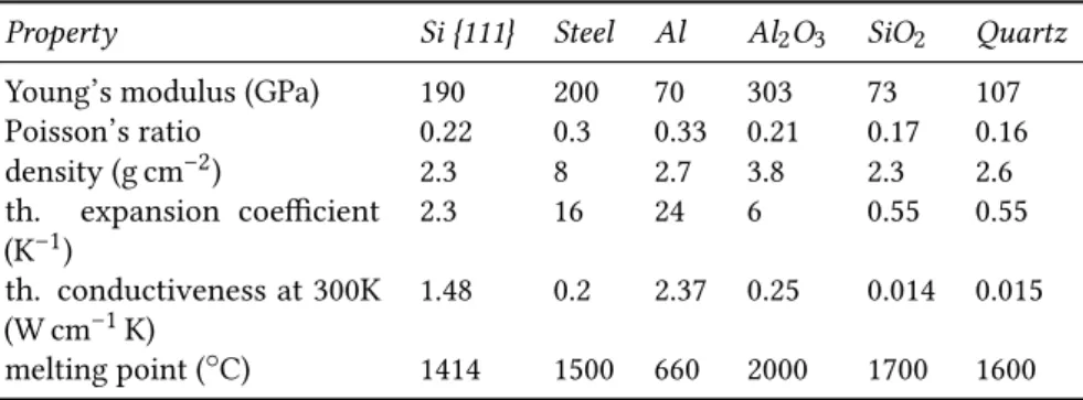
Single-crystal silicon has great mechanical properties (e.g. Young’s modulus is comparable with the one of stainless steel), it’s lighter than aluminium and its Knoop hardness is twice the one of iron. Silicon me-chanical properties are anisotropic, that is they depend on the crystal’s orientation. The following table makes a comparison between silicon and other semiconductor industry’s related materials.
Only in the ’90s, the research was undertaken to obtain a complete inte-gration of microelectronic circuits and mechanical structures, enabling the realization of actuators, sensors and electronic control circuits in a single silicon chip: a MEMS. MEMS are a growing market, focusing primarily on: inertial sensors (accelerometers and gyroscopes), pressure and flow sensors, chemical sensors, microfluidic structures (print heads for ink-jet, medical diagnostics, drug delivery, micropumps) and optical applications. The devices and MEMS structures are fabricated using
Table 2.1: Comparison between silicon and other materials main properties.
Property Si {111} Steel Al Al2O3 SiO2 Quartz
Young’s modulus (GPa) 190 200 70 303 73 107
Poisson’s ratio 0.22 0.3 0.33 0.21 0.17 0.16 density (g cm–2) 2.3 8 2.7 3.8 2.3 2.6 th. expansion coefficient (K–1) 2.3 16 24 6 0.55 0.55 th. conductiveness at 300K (W cm–1K) 1.48 0.2 2.37 0.25 0.014 0.015 melting point (◦C) 1414 1500 660 2000 1700 1600
both conventional techniques for integrated circuits, such as lithogra-phy, deposition, etching, and a wide range of techniques developed ad hoc for the micromachining of silicon. For all types of MEMS, there are two approaches to silicon processing: the bulk micromachining and the surface micromachining.
2.2.1
Bulk micromachining
Bulk micromachining technology is based on the removal, by chemi-cal etch, substantial portion of silicon from the substrate: in this way suspended and movable structures such as membranes and cantilevers, trenches, or structures of different types can be obtained. The attacks used are compatible with the electronics on the chip. This has allowed to combine bulk micromachining technology with the CMOS (Comple-mentary Metal-Oxide-Semiconductor), which is the point of reference for the rest of our discussion. A first classification of the attacks can be made according to the geometry of the excavations obtained: according to this criterion, the attacks are divided into isotropic and anisotropic. The first, thanks to the same attack speed in all directions allows to create rounded excavations. With the latter, instead, high-aspect ratio structures with flat and well defined surfaces can be obtained. Bulk micromachining can be further divided into two different techniques: if the removal of the silicon is from the front of the wafer it is called front
bulk micromachining, if it happens from the back it is called rear bulk micromachining.
2.2.2
Surface micromachining
Although the approach followed initially for the manufacture of mi-crosystems and sensors has been the bulk micromachining, recently the attention is focusing on the complementary technique: the surface micromachining. In fact, it offers better possibilities of processing; it is based on the deposition and patterning of thin films on the surface of the wafer. These deposited materials often act as spacer or as sacrificial layer: once removed they allow the creation of complex suspended structures, three-dimensional or movable. Typically the materials used are silicon oxide as a sacrificial layer and polysilicon as structural layer. The oxide is deposited by CVD (Chemical Vapour Deposition) as its growth and its etching are faster than an oxide grown thermally. Although there are other kind of materials that have been tested for the realization of micromachined structures, such as polysilicon and silicon nitride, nickel and copper, copper and Ni/Fe, the most used are still SI02 and
polysilicon. The major issues of surface micromachining that engineers should care about are:
a) control of mechanical properties of structural layers to prevent the formation of residual stresses;
b) structure sticking in the drying phase following a wet etch There are several methods, described in the literature, to try to solve the problems described above [34] in fact nowadays MEMS engineers can build astounding silicon structures.
2.2.3
MOEMS applications
Integrated optic is a field where there are a lot of microsystems applica-tions. MOEMS is in fact an acronym for Micro-Opto-Electro-Mechanical-Systems. The main drive that led to the development of these objects
2006 2007 2008 2009 2010 2011 2012 2013 2014 2015 0 50 100 150 200 250 300 Million of US$
Figure 2.1: Optical MEMS for fiber optic telecom market
was given without doubt by the field of telecommunications. Follow-ing the 2001 telecom downturn, some companies explored several new applications that are widespreading the use of optical MEMS. Despite the difficulties global market has encountered in the last few years MOEMS market has started rising again. iSupply market analysts ex-pect solid growth from 2009 through 2015 [35]. Behind this growth can be found some facts: 1) the CAGR of the Internet is about 45-50%, 2) video traffic over the net keeps rising (thus increasing bandwidth demand), 3) in China in the next few years there will be huge optic fiber deployments (boosted by the government) and a consequential growth of Passive Optics Networks (PON) market of about 33% in 2009-2014 (see Fig. 2.1). Beside this, Fiber To The Home (acsFTTH) paradigm will become dominant and there will be the need for more agile networks instead of more fibers. The use of MOEMS based devices allow designers to achieve a greater grade of flexibility and reconfigurability as opposed to more conventional approaches. Micro optical systems find a piv-otal role in telecommunications. Today, long distance and broadband communications are via fiber optic netwprks. Generally the bottleneck is represented by the electronics, hence the search for solutions that allow to manage light signals on chips without the necessity of having to convert them into electrical signals. Thus most of the applications of MOEMS are in the telecommunication field and concern switching and multiplexing of optical signals through micromirrors or array of
micromirrors. The advantage of using production technologies of in-tegrated circuits makes possible to create miniaturized mirrors with low cost and low energy consumption compared to the use of macro-scopic reflective surfaces. Currently other sectors in which MOEMS have potential applications are:
- Displays (DMD); - Spectrometry; - IR imaging; - Barcode Readers; - Picoprojectors;
- manufacturing processes: stereo photolithography, laser-assisted deposition and patterning, packaging, assembling;
- sensing: optical encoders, optical memories, microscopes in the near field, sensors for optical fibers and waveguides.
Display (DMD)
The ability to reflect light in a continuous manner or not divides cromirrors into two categories: the first they are called scanning mi-cromirrors, in the second digital micromirrors. The Digital Micromirror Device (DMD) belongs to the second category: is a spatial light modu-lator developed by Texas Instruments that is the core of Digital Light Processing (DLP) projection technology, and was invented in 1987. A DMD chip has on its surface several hundred thousand microscopic mirrors arranged in a rectangular array which correspond to the pix-els in the image to be displayed [36]. The mirrors can be individually rotated ±10° – 12°, to an on or off state. In the on state, light from the projector bulb is reflected into the projection lens lighing up the pixel on the screen. In the off state, the light is directed elsewhere (usually onto a heatsink), making the pixel appear dark. To produce greyscales, the mirror is toggled on and off very quickly, and the ratio of on time to off time determines the shade produced (binary pulse-width modu-lation). Contemporary DMD chips can produce up to 1024 shades of gray. The two main application of DLP systems are front projectors (small standalone projection units) and DLP rear projection television.
Projectors can be equipped with a single DMD chip or with three chips. The first solution employs a spinning colour wheel between the light source and the DMD. The colour wheel is usually divided into four sectors: the primary colours: red, green, and blue, and an additional clear section to boost brightness. Since the clear sector reduces colour saturation, in some models it may be effectively disabled, and in others it is omitted altogether. Some projectors may use additional colours (for example, yellow). The DMD chip is synchronized with the rotating motion of the colour wheel so that the green component is displayed on the DMD when the green section of the colour wheel is in front of the lamp. The same is true for the red and blue sections. The red, green, and blue images are thus displayed sequentially at a sufficiently high rate that the observer sees a composite "full colour" image. In early models, this was one rotation per frame. Later models spin the wheel at two or three times the frame rate, and some also repeat the colour pattern twice around the wheel, meaning the sequence may be repeated up to six times per frame.
A three-chip DLP projector uses a prism to split light from the lamp, and each primary colour of light is then routed to its own DMD chip, then recombined and routed out through the lens. Three-chip DLP pro-jectors can resolve finer gradations of shade and colour than one-chip projectors, because each colour has a longer time available to be modu-lated within each video frame; furthermore, there won’t be any flicker or rainbow effect like with the single chip solution. Like three-tube CRT projectors, the optics for some three-chip DLP projectors must be carefully aligned. But it’s more common to use a prism which makes it necessary for only one optic, instead of three, and therefore removes the problem of colour separation. The three-chip projectors used in movie theatres can produce 35 trillion colours, which many suggest is more than the human eye can detect. The human eye is suggested to be able to detect around 16 million colours, which is theoretically possible with the single chip solution. However, this high colour precision does not mean that DLP projectors are capable of displaying the entire gamut of colours we can distinguish (this is fundamentally impossible with any system composing colours by adding three constant base colours).
(a) One-DMD DLP projector (b) Three-DMD DLP projector
(c) Schematic view of two adjacent
micromirror-based pixels
Figure 2.2: DMD overview
Spectrometry
A spectrometer is an optical instrument used to measure properties of light over a specific portion of the electromagnetic spectrum, typically used in spectroscopic analysis to identify materials [37]. The variable measured is most often the light’s intensity but could also, for instance, be the polarization state. The independent variable is usually the wave-length of the light, normally expressed as some fraction of a meter, but sometimes expressed as some unit directly proportional to the photon energy, such as wavenumber or electron volts, which has a reciprocal relationship to wavelength. A spectrometer is used in spectroscopy
Figure 2.3: A commercial microspectrometer based on MOEMS devices [source: Hamamatsu]
for producing spectral lines and measuring their wavelengths and in-tensities. Spectrometer is a term that is applied to instruments that operate over a very wide range of wavelengths, from gamma rays and X-rays into the far infrared [38]. If the region of interest is restricted to near the visible spectrum, the study is called spectrophotometry. A new class of spectrometers can be designed using programmable components such as MOEMS which enable to tune the beam in spectra width and central wavelength. The advantages due to MOEMS technology can be resumed in the replacement of the macroscopic mirror and its drive with an oscillating micro-mirror. This enables: increased reliability and ruggedness, system miniaturization, cost reduction and ultra-rapid scan capability. A sub cm prototype based on MOEMS piezoelectric micro-grating for fluorescent lifetime detection in biological tissues has been presented by Lo et al. [39]. Japan firm Hamamatsu has in its portfolio of products several MOEMS based mini spectrometers (see Fig 2.3), whose internal optical system is comprised of a convex lens on which a grating is formed by nanoimprint.
IR imaging
There are two classes of infrared detectors that can be used to manu-facture IR cameras: cooled and uncooled. Cooled detectors - named for
(a) a MEMS microbolometer (b) Using an IR sensor it is possi-ble to detect obstacles otherwise not visible at night
Figure 2.4: IR sensor and application
their reliance on a cryogenic cooling mechanism - are extraordinarily sensitive to infrared radiation. The cryocooler substantially reduces thermal noise down to very low levels. InGaAs or HgCdTe are the most common materials used in cooled detectors. Because the cryocooler unit is a mechanical device with moving parts, cooled detectors usu-ally require maintenance after a period of time, often for every 8000 to 10000 hours of operation. Uncooled infrared detectors have become an excellent alternative and are much more commonly used in many commercial, industrial and military IR camera products. Because they do not require the use of a cryogenic cooling unit, infrared cameras that use uncooled detectors enjoy substantial advantages in maintain-ability as well as a significant reduction in size, complexity and cost. The primary type of uncooled detector today is the microbolometer, a device based on MEMS technology. When infrared radiation in the wavelength range between 7 and 13 µm strikes the microbolometer’s detector material and is absorbed, it heats up, and the resulting change in its electrical resistance is the basic sensing technique. These changes are processed by separate core electronics to create a thermal image. These detectors are quite sensitive and can sense heat radiated from objects, depending upon their temperature. In this way it is possible to detect variation in the range of tens of milliKelvin at 60 Hz [40–42]. High performance, high reliability and lower cost make a-Si detectors ideally
suited for many IR applications in both commercial and military sectors (night-vision including security and basic surveillance). IR detectors and cameras are now becoming standard in automobiles as night-vision systems. Thermal imaging cameras have also been used for airport fever screening.
Barcode Readers
The barcode scanners are available in various types; the basic princi-ple of all the types is projecting light to the bar code and identifying the width of each bar based on the quantity of reflected light from the bar [43–45]. This bar code scanning can be done by either of the fol-lowing two methods. One of the method is such that a fine beam spot is scanned perpendicularly to code bars and reflected from each bar is scanned one after another by a single photodetector element. The other method is to projecting light evenly to the bar code surface and scanning the reflected lights from the code bars simultaneously by a photode-tector or CCD (Charged Coupled Device) image sensor composed of a plural photodetector elements provided correspondingly to the code bars. Laser based bar code scanning engines provide advantages over other scanning methods such as greater scan distance, larger bar code capability, reduced ambient light susceptibility, and ability to read on irregular surfaces. Due to the size reduction and high integration of this system MOEMS are the best choice for this type of optical system. A MOEMS-based laser bar code scanner provides these same advantages with higher reliability at a lower cost. The manufacturing techniques for fabricating MEMS devices enable lower cost of production. US firm Microvision put on the market a barcode reader device based on MOEMS (see Fig. 2.5).
Picoprojectors
In the near future, innovative optical technologies based on solid state lighting (LEDs and laser diodes) and MOEMS technology will allow the development and diffusion of low cost light engines, pushing the market
Figure 2.5: A commercial barcode reader based on MOEMS devices [source: Mi-crovision]
of Head Up Displays (HUD) and picoprojectors. The aim of picopro-jectors is to realize low size, high performance portable propicopro-jectors for notebook or palm PC and to realize integrated projector for handheld devices, like cell phones or digital cameras [46]. However mixing solid state lighting and MOEMS require innovative solutions mixing optics, thermal management, electrical power conversion, electronic drive cir-cuitry. Although there are many technical issues to be solved regarding packaging, thermal management, cost/performance ratio, the first pico-projectors suitable for use in a mobile phone have been demonstrated by US firm Microvision at the Global press Summit Conference in San Francisco in April 2008. Nowadays there are several consumer elec-tronic products (see Fig. 2.6) that use MOEMS picoprojectors: Nikon’s S1000pj digital compact camera, Sony’s HDR-PJ50V camcorder, 3M’s CP40 camcorder projector, and of course Microvision’s general purpose SHOWWX+TM laser picoprojector.
(a) SONY HDR-PJ50V pico projector camcorder
(b) Microvision SHOWWXTM pico projector
(c) NIKON S1000pj pico projector cam-era
(d) 3M’s CP40 camcorder
Figure 2.6: Some consumer electronic products featuring MOEMS based laser picoprojectors
2.3
Scanning micromirrors
A scanning micromirror rotates around the axis of torsion until the mechanical torque moment of the spring equals the drive one. There are various categories of scanning micromirror according to the type of im-plementation. The performance of an integrated scanning micromirror are determined by:
- maximum scan angle; - resonant frequency; - resolution;
- flatness and smoothness of the surface.
To obtain high resolution images are required relatively large mirrors and large scan angles. The resolution, defined as the number of re-solvable spots is a function of divergence of the incident beam and the maximum scan angle according to the function:
N = θmax δθ =
θmaxD
aλ (2.1)
where ∆θ is the divergence of the incident beam, θmaxthe maximum scan angle, D the diameter of the mirror, λ the length of the incident light and a the form factor of the crack (a = 1 for crack square and a = 1.22 for the circular ones). The max scanning speed depends on geometry and mechanical properties, that is the mass and elastic constant of the spring part of the actuator. In fact, the natural frequency for torsional moving is:
ω0 = 2πf0 =
r k
I (2.2)
where k indicates the elastic constant of the spring and I the moment of inertia. For a square mirror the moment of inertia is:
I = 1 12
mL2 (2.3)
where m is the mass of the mirror and L the side. It can be seen therefore that the larger the mirror, the lower the scanning speed. Not only the
Table 2.2: Currently available resolutions. VGA 640 × 480 SVGA 800 × 600 XGA 1024 × 768 SXGA 1280 × 1024 16 : 9 1280 × 720 SXGA+ 1400 × 1050 2k 2048 × 1080
performances, but also the technology of manufacture and the type of implementation of the micromirror depend on its dimensions, which can range from microns to a few millimeters. A first classification based on dimensions may be as follows:
- more than 2 mm: it is more convenient an implementation of electromagnetic type, as the torque moment produced by the Lorentz Force is proportional to the area of mirror; to maintain the smoothness of surfaces so large, the mirrors are made using monocrystalline silicon (SCS) derived from a silicon substrate or from SOI (Silicon on Insulator) structures;
- between 250 µm and 1 mm: it is better to create comb drive elec-trostatic actuators from SOI structures;
- smaller than 250 µm: typically are used parallel plates electrostatic actuators and technologies like surface micromachining.
The DMD are mainly used for applications such as digital cinema (2K resolution) and household headlights of high quality. The resolutions currently available are listed in Table 2.2.
The DLP micromirror can rotate ±12° in base of the digital value of the signal of SRAM present below each mirror. So the positions in which each mirror can be found are two: totally imbalanced to one side or the other
After the application of voltage, according to its value, it generates a force of electrostatic attraction, which can make the mirror stand still in
Figure 2.7: Micromirror-based optical matrix switch [source: Calient]
his position or rotate it in the opposite direction. Each mirror is associ-ated with a pixel and can be moved to reflect light toward the screen (on position) or outside of it (off position). The light intensity of the pixel is determined by the drive voltage of the micromirror, which is of type PWM: varying the amount of time in which a micromirror assumes one of two positions, it is possible to modulate the light intensity of each reflected point on the screen.
With a single DMD chip it is possible create all the colors, using the high speed of micromirrors switching. By placing a wheel formed of dichroic cloves between the lamp and DMD, it is possible send to the DMD array one color at a time, leaving to the eye-brain system, the task of integrating over time information about color, to addition various components and give to the gaze all colors of the projected images For digital cinema applications are used systems with three DMD, each separately to modulate red, blue and green.
In recent years, the main area of application of the bi-axial scanners has been the telecommunications in the DWDM (Dense Wavelength Division Multiplexing) networks, where there is the need of optical interconnections with a large number of doors. Using two micromirror arrays, each mirror associated to the input array can point to the output mirror, as it is illustrated in Figure 2.7. The number of channels of
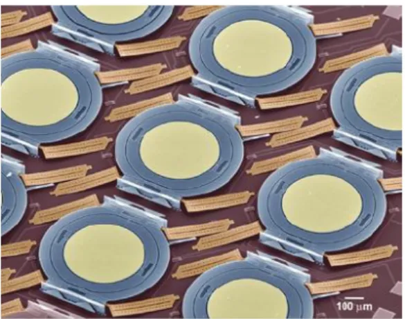
Figure 2.8: Array of electrostatic actuated parallel plates scanning micromirrors for optical switching applications.
this configuration is limited by the size, flatness and scan angle of the mirrors. They are realized with monocrystalline silicon in order to obtain a good flatness. In fact such structures realized with polysilicon through surface micromachining present a considerable curvature due to residual stress of thin films. Another use of bi-axial scanners is the raster scan projection, that is to use a system that includes micromirror and one or more lasers; it is thus possible to produce projections of images [47].
2.3.1
Electrostatic actuation
It is possible to identify two types of scanners: those based on actuators with flat parallel plates (Figure 2.8) and those based on comb drives. Generally high driving voltages are required to achieve electrostatic. To reduce or avoid high driving voltages designers can:
a) use springs with more compliance;
b) increase capacitance between mobile and fixed electrode;
c) use packaging techniques that allow to create a vacuum around the micromirror, thus reducing friction and obtaining better per-formances.