Design of Implanted RFID Tags for Passive Sensing
of Human Body: The STENTag
Cecilia Occhiuzzi, Member, IEEE, Giordano Contri, and Gaetano Marrocco, Member, IEEE
Abstract—Numerical processing of passive UHF-RFID tags’
response may provide physical insight about the hosting object or about the nearby environment. This idea is here extended to implanted antennas with the purpose to sense the evolution of some human physiological and pathological process involving a local change of effective permittivity inside the body. The goal is to understand how master the design of this class of devices taking into account both communication and sensing capabilities. An ad hoc design methodology is here presented and discussed by means of a realistic medical case concerning the modification of an endo-vascular device to achieve a STENTag able to sense the state of the vessel wherein it has been implanted.
Index Terms—Biosensor, implantable biomedical device, passive
sensing, RFID.
I. INTRODUCTION
B
ESIDE the common applications to Logistics, the Radio Frequency Identification (RFID) technology has been re-cently recognized as potentially capable to produce additional information about the tagged object, such as its physical state and its time-evolution, without any specific embedded sensor or local power supply [1]. The physical rationale of this idea, for which the tag acts as a self-sensing device, lies in the depen-dence of the tag’s input impedance and of its radar cross sec-tion on the physical and geometrical features of the tagged ob-ject or, more in general, on the close surrounding environment. The possibility to monitor processes in evolution discloses in-teresting opportunities in telemedicine and human health mon-itoring in general, especially concerning implantable devices. One or more battery-less RFID radio-sensors could be inte-grated into implanted medical devices such as prosthesis, su-tures, endovascular devices and orthopedic fixings, and then in-terrogated by an external reader (Fig. 1). By data acquisition at different times (days or even hours), the change history of geo-metrical or chemical features of the tissues could be collected, thus observing in an indirect way the healing process and pos-sible complications, e.g., abnormal cell proliferation, edema and inflammatory events.In general, the critical issues in the design of implanted radios are the feasibility of a reasonable link range [2], the low power Manuscript received April 08, 2011; revised December 31, 2011; accepted February 25, 2012. Date of publication May 07, 2012; date of current version July 02, 2012.
The author are with the DISP-University of Roma Tor Vergata, Via del Politecnico, 1, 00133 Roma, Italy (e-mail: [email protected]; [email protected]).
Color versions of one or more of the figures in this paper are available online at http://ieeexplore.ieee.org.
Digital Object Identifier 10.1109/TAP.2012.2198189
Fig. 1. The change of the electromagnetic response of implanted RFID tags may be related to a biologic process in evolution inside the human body.
consumption [3], biocompatibility [4] and miniaturization [5]. Implanted RFID tags were used in the past for tagging animals. Passive devices for human identification purposes have instead been proposed very recently in [6], as well as implantable an-tennas suitable to host biological sensors (blood-pressure [7], temperature, glucose). Patch-like antennas [2] and monopole-like antennas [8] have been studied for subcutaneous implants, while first examples of ingestible RFID capsules interrogated by a wearable reader can be found in [9].
Up to now, no attempt has been reported, according to our knowledge, to extract sensing data from passive RFID implanted sensor-less tags in addition to more traditional identification codes. Beside the critical issues shared by con-ventional RFID and implanted antennas, the very big challenge is the control of the sensitivity and of the dynamic range of the tag-as-sensor during the design task in addition to the usual communication requirements. Biological processes are characterized by a great variety of dynamic ranges in terms of evolution timeline and amplitude [10]–[14]. Some pathologies may show very slow and moderate evolutions, while in other cases, especially during acute events, rapid and large tissues modifications may be observed: the measurable response of RFID radio sensor needs therefore to be properly correlated to the process under observation. In any case, the problem is even more challenging due to the high permittivity and high losses of living tissues. As proved in [1], the electrical parameters of an RFID tag (impedance and gain) in these conditions are expected to be very little sensitive to the variation of the dielectric properties, because of the smoothing effect induced by the losses.
This paper proposes a complete procedure for the design of self-sensing implanted tags, here described with specific focus to the monitoring of biological ducts hosting a stent implant. A stent is a metal-mesh tubular device used to recover a stenosis [15], an abnormal narrowing in a blood vessel or in other tubular 0018-926X/$31.00 © 2012 IEEE
organ or structure, e.g., the occlusion of an artery due to ab-normal accumulation of atherosclerotic plaque. The stent is sur-gically implanted into the vessel, then expands, keeps the vessel open thus improving blood flow, and stays in its seat perma-nently. Unfortunately, this procedure is not definitive since a new accumulation of tissue inside and around the stent may give rise to risk of in-stent restenosis (ISR). A common post-surgery requirement is thus monitoring the device status, or in other words the sensing of its local environment over time.
Starting from the basic equations governing the RFID sensing, it will be here shown how to choose the IC family, and in particular how to match the implanted antenna in order to maximize its sensitivity to the variation of the physical pa-rameter under observation. Finally, by the help of a laboratory phantom, the design procedure is fully experimented over a stent prototype, the STENTag, in both fixed-and multi-fre-quency modalities.
II. RFID-SENSINGEQUATIONS ANDDESIGNSTRATEGIES We denote with a local physical or geometrical param-eter of the body region which has to be monitored by the RFID platform. Specifically, will be a shape factor of the biolog-ical process or, more generally, the local effective permittivity “sensed” by the tag’s antenna.
The two-way reader-tag link [16] for UHF-RFID systems (overall World-wide band: 866–956 MHz) is commonly char-acterized under the far field assumption by using the Friis formula for the direct path, and the radar cross-section for the reverse one. Although the electromagnetic interaction with the human body is much more complicated, the free-space formalism is nevertheless here considered with the purpose to simplify the design methodology described next. The reliability of this choice will be discussed in Section III by the help of an accurate numerical simulation involving a realistic body phantom.
The conventional RFID formulas are hence rewritten making explicit the dependence on the variation of local parameters with the purpose to obtain some sensing metrics which can be derived by the reader’s measurements. The power collected by the IC (1) and the power backscattered by the tag toward the reader (2) and collected by it, are
(1) (2) where is the reader-tag distance, is the gain of the reader antenna, is the gain of the tag’s antenna when placed into the body which hence includes all the absorp-tion and obstrucabsorp-tion phenomena in the inside-to-outside (and converse) propagation. is the power entering the reader’s antenna, is the polarization mismatch between the reader and the tag, is the power transmission coefficient of the tag
(3)
with and input
impedance of the RFID IC and of the antenna, respectively. is the tag’s radar cross-section
(4) The backscattered power , is strictly correlated to the physical variation of the local environment through the change of impedance and gain of the tag.
A second indicator which can be measured by the reader is the turn-on power , e.g., the minimum input power through the reader’s antenna forcing the tag to respond. It can
be derived from (1), by imposing being
the IC sensitivity provided by the manufacturer
(5) The presence of the multi-path, caused by the interaction with the environment, is not taken into consideration here because of the expected small reader-tag distances achievable within the allowed emitted power. It was demonstrated in [17] that for low-gain tags, as in case of implanted antennas, the free-space formula is still useful to predict the read region.
The two indicators in (2) and (5) may be used as data inver-sion curves between measured data and the evolution of the process. It could be useful to normalize each indicator by its value in a particular reference state, say , for instance col-lected at the time of the tag placement into the body.
A. Design Parameters and Strategies
The idea of self-sensing tags implies that there is no decou-pling from the operative and structural point of view, between antenna and sensor, more precisely the antenna is the sensor and the sensor is the antenna. The sensitivity and the dynamic range of the system are thus strictly connected to the antenna’s fea-tures, in particular to its quality factor, and definitely to its band-width (related to the tag’s realized gain [18]). Due to the high water content, however, human tissues are characterized by high permittivity and significant losses, so that the implanted tag will exhibit a large bandwidth and hence a generally poor sen-sitivity to the change of the local environment.
There are at least three degrees of freedom available to master the sensing performances of such a class of devices. The first one is the shape of the antenna which is however mainly con-strained to medical requirements so that only a modest geomet-rical change is allowed. The second degree of freedom is the IC family having a specific power threshold and input impedance. As reported in [20], tags matched to ICs with very high phase angle (the ratio Q between the imaginary and the real part of the input impedance) exhibit higher sensitivity to the variation of antenna impedance vs. the change of the tagged objects and therefore they are preferred for sensing activities. The last avail-able option is the state (real or virtual) of the biological process where forcing the antenna to have the best impedance matching to the RFID IC. In this condition is referred to as matched state. As recently investigated in [1] the choice of the matched state affects the position of the peak of power transfer coefficient versus the dynamic range of the process so that it is
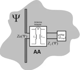
Fig. 2. Reference model to investigate the key issues in the design of implanted tags. Given a radiating structure, an antenna adapter is used to match such an an-tenna to a specific IC in a particular state (the matched state) of the process to be observed.
possible to shift, and hence to localize, the curve of any sensing indicator vs. the change of the process parameter. By means of such a shaping of the data inversion curve it is expected to be able to emphasize the antenna response at the worsening of the pathology or instead to amplify the sign of healing.
The design parameters are here correlated together according to the reference model in Fig. 2 where the tag’s antenna is con-nected to the IC via an Antenna Adapter . This one vir-tually applies to the antenna impedance and yields a trans-formed impedance which is matched to the specific IC such to get the best power transfer in the particular state of the process (the matched state). The key parameters of the self-sensing tag are hence inter-correlated by the following matching equation:
(6) In (6) the asterisk denotes the complex conjugate, the indicates the design conditions and the specific state of the process where the antenna’s impedance is evaluated.
The effect of the antenna adapter could be obtained [18], for instance, by an inductively coupled loop placed in the close proximity of the radiating structure, a T-match or, more simply, by adding discrete inductors/capacitors, as shown later on in the experimental Section.
Following the previous considerations, it is possible to define basic guidelines to engineer the data inversion curves according to the specific process under monitoring, for instance to empha-size the variation of the early or late state of the process, as re-quired case by case.
Denoting with the set of states describing the evolution of the process under monitoring, it is required that the inversion curve (say in general) is monotonic in and with a given overall variation , e.g.,
(7)
Moreover the radio-sensor has to be subjected to constraints
over the maximum interrogation power in
order to permit a suitable transcutaneous communication, at a given body-reader distance, for the whole process’s evolution and in agreement with power regulations or with the expected capabilities of the reader
(8) The shaping of the radio-sensor’s response is mainly reduced to an iterative search for the most appropriate IC and mostly for the status of the process where maximizing the power collected by the IC. The design procedure is coded as follows:
i) select the antenna shape together with the topology of the antenna adapter (a T-match, a coupled loop, or even discrete inductors/capacitors). These choices will be sub-jected to the specific medical constraints, the implantation locus and the available space over an existing implantable device, if any;
ii) select the most suitable IC family ( with the highest impedance phase angle Q;
iii) select a guess value for the matched state , belonging or not to the process evolution . For instance the first guess for could be that corresponding to the healthy condition or instead to the severe hilliness;
iv) calculate the corresponding input impedance ; v) estimate from inversion of (6) the parameters of the
antenna adapter so that the transformed impedance of the antenna appears matched to the IC;
vi) calculate the turn-on power and the backscattered power
for all ;
vii) verify the sensing and communication constraints in (7) and (8);
viii) if such conditions are matched then the parameters of the antenna adapter found in v) will give the final design; ix) if the check in vii) is instead unsuccessful, then modify
the matched state and/or select a different IC and jump back to step iv).
The tag response to the process’ changes (described by the impedance and the gain) needs to be estimated by measurements over phantoms, or even better by application of numerical elec-tromagnetic models.
More in general, even the shape of the antenna, as well as the topology of the antenna adapter, could be introduced in the iterative loop of the design, with many more degrees of freedom but at the cost of highly increased computational complexity.
The design procedure is now illustrated with reference to a realistic medical case, e.g., the design of the STENTag, able to sense the healthy condition of an artery.
III. THESTENT
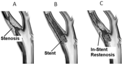
The in-stent restenosis (Fig. 3) could begin just after the im-plant of the stent into a body duct, due to hyper proliferation of neointimal cells (similar to muscular tissue) [13], as well as in a longer period due to the accumulation of new tissue, such as atherosclerotic plaques (similar to a mixture of water and fatty tissue) [14]. From a clinical and a prognostic point of view, the ISR can be usefully classified according to its evolution pattern
Fig. 3. Stenosis, stenting procedures and in-stent restenosis of a biological duct. Adapted from [22].
and grade. A possible site of stenting and hence of ISR is the carotid. As reported in [23], a more that 40% diameter reduc-tion of the vessel can be considered critical for the safety of the patient, while a reduction of more than 80% must be regarded extremely dangerous and requires a further surgical treatment. The most severe forms if IRS occur when the lesions are wide ( mm long) and extend beyond the margins of the stents. This latter form is referred to as diffuse proliferative ISR.
Since a vascular stent is typically fabricated with biocompat-ible metallic alloys, for instance the Nickel-Titanium (Nitinol) [24] with nice conducting features, some researchers have re-cently proposed to use the stent itself as a radiating elements to set-up a transcutaneous wireless telemetry system [25] where the status of the vessel is detected by a dedicated sensor inte-grated on board the stent. The idea to use the stent as sensor of restenosis has been instead investigated in [26], by relating the presence of cell proliferation and tissue growth to a low fre-quency (0.1 Hz to 10 MHz) impedance measurement. However, the wired nature of the device (being necessary catheters to mea-sure the impedance of the stent), makes the described platform not suited to a wireless telemetry system.
The stent is instead a natural candidate to achieve a self-sensing implanted RFID tag which would combine both me-chanical and sensing capabilities. This new device, hereafter de-noted as “STENTag”, has been obtained from an existing stent after minimal geometrical modification and by the inclusion of an RFID IC.
The design guidelines in Section II, are applied to a commer-cial cm long self-expanding stent [27]. The Antenna Adapter is here reduced to just an inductor connected in series to the chip, and hence the transformed impedance of the STENTag will be simply
(9) The considered IC is the NXP-G2X having power sensitivity
dBm and impedance at 870 MHz
(corresponding to impedance phase angle ). The IC is integrated into the device by means of an additional cm long Nitinol straight wire, protruding from the tubular grid (Fig. 8). The resulting object may be regarded as an asymmet-rical dipole, with a hollow branch. Although a real implant of this augmented stent should require additional work, aimed to properly shape the added Nitinol wire and to preserve the bio-compatibility, nevertheless this geometry is useful to demon-strate the design methodology and to understand the achievable sensitivity.
The process evolution to be monitored is the proliferation of tissue inside the stent, according to typical diffuse prolifera-tive patterns: as the ISR increases, the healthy tissue (normally blood) is progressively replaced by neointima (muscle cells pro-liferation), up to stimulate, in the very long period, the possible formation of new atherosclerotic plaque. Because of all those tissues are characterized by different dielectric properties, the parameter to be sensed is the equivalent complex permit-tivity inside the stent. The desired STENTag should have an overall variation of the power response of not less than 3 dB between the healthy condition and the full atherosclerotic restenosis, e.g.,
% (10)
and a required turn-on power similar to the power emitted by hand-held smartphones
(11) A. Model
The application of the proposed methodology requires to set-up a numerical model of the neck and of the in-stent restenosis. Accurate digitalized body phantoms (one for all, the Visible Human [28]) are now available, and provide as-sessed databases of electromagnetic parameters of the organs. These models could be in principle used together with a Finite Difference Time Domain (FDTD) tool to predict the tag’s response in presence of the restenosis’ evolution. However, since laboratory experimentations have to be performed, and human or even animal implants are not feasible in this phase, a more simplified cylindrical model has been considered. It offers a reasonable control of the restenosis grade and, above all, it can be easily manufactured and experimented with high reproducibility.
The neck is hence simulated by cylinder of diameter cm and height cm filled by a homogeneous dielectric having the weighted average permittivity of all the main tissues
composing the neck, , while a smaller
off-centered 0.8 cm-diameter cylinder simulates the human carotid and it is filled by blood-like dielectric . The sizes of the phantom have been chosen such to reproduce the overall characteristics of Visible Human model. In particular the height of the cylinder comprises also the bulk of the head and part of the shoulders.
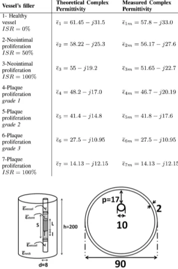
The STENTag will be inserted inside the middle of the smaller cylinder, tight fitting its internal surface, in a localized volume simulating the diffuse proliferative restenosis. Such a district, of height cm, is homogeneously filled with a dielectric with variable permittivity ( . It is worth noticing that, although the proposed model sensibly simplifies the ISR patterns, it could be assumed as a reasonable approximation of the phenomena, since the radial increase/decrease of the diffuse proliferative IRS can be converted into the change of an homogeneous dielectric having the weighted average permittivity of all the healthy and the unhealthy portions of the vessel. As specified in Table I seven conditions have been
TABLE I
RE-STENOSIS: PROPERTIES AT870 MHZ OF THEVESSEL’SDIELECTRIC
Fig. 4. Cylindrical model of the neck, the carotid and the ISR (side view and top view). The STENTag is inserted in the middle of the smaller cylinder, tightly fitting its internal surface, as in a real-life implant. The ISR is modeled has a localized (shadowed) volume with variable permittivity extending beyond the margins of the stents. Size in [mm].
simulated, starting from the blood, passing through the neoin-timal proliferation, down to a plaque restenosis. Finally, the meshed tubular part of the STENTag has been simulated as a continuous cylindrical surface as in [25].
The physical reliability of the considered cylindrical model has been preliminary validated in comparison with a more real-istic anthropomorphic numerical phantom based on the Visible Human database, which includes a true description of the carotid and the surrounding tissues. At this purpose, a reference 2.5 cm dipole ( in the body), insulated by a 2 mm-thick teflon coating, has been introduced within the two carotid models at corresponding positions (Fig. 5), assuming an healthy vessel, e.g., in absence of restenosis.
The results obtained by FDTD simulations are visible in Fig. 6 for what concerns the input impedance of the antenna and the electric field along the -line passing through the dipole’s axis. The impedance estimations by the two models are quite in agreement with less than difference in the entire UHF (World-Wide) RFID Band. This is an expected result since the
Fig. 5. Electromagnetic field (dB scale) radiated by a 2 mm-teflon-coated half-wave dipole implanted into the human carotid. Left) Frontal cross-section of Visible Human FDTD phantom; Right) Simplified cylindric phantom. The dipole is placed inside the carotid at position cm and cm in both the models.
Fig. 6. (Left) Electric field along the x-axis (at height cm corre-sponding to the dipole’s center) radiated by a half-wave dipole implanted in the human carotid for the two different numerical phantoms of Fig. 5. The typical far-field profile has been also superimposed. (Right) Input impedance of the same dipole as predicted by the two numerical phantoms.
high losses of the human tissues force the interaction with the antenna to be very local. The cylindrical phantom is therefore adequate to capture the significant physics of the neck, at least in the considered frequency band.
Concerning the outside radiation, it can be observed that the field profiles are almost overlapped and well fitted by the curve indicating the typical far-field attenuation. Therefore, just after a distance of about 15 cm from the locus of the implant, it is reasonable to assume the far-field approximation and hence to apply the equations in Section II to extract the RFID parameters of the STENTag, required for the design.
B. Design Procedure
Once fixed the antenna’s shape, the topology of the antenna adapter, the RIFD IC, the design constraints and the models simulating the biological process under investigation, it is pos-sible to iteratively apply the design procedure in Section II in order to search for the most suitable matched state and the corresponding value of the inductance . In all the consid-ered cases the electromagnetic model is solved by an FDTD tool which directly provide the antenna gain and impedance, while the derived power functions in (2) and (5) are then ob-tained in post-processing assuming a reader-tag distance of 20 cm and a 5 dB-gain reader’s antenna in linear polarization. Fig. 7 shows the backscattered power as in (2) normalized to the turn
on power and the turn-on power as
Fig. 7. Normalized backscattered power and turn-on power of the STENTag simulated at 870 MHz during the ISR process for three different choices of the matched state. The simulated data are sorted according to the real part of the considered complex permittivity.
Fig. 8. STENTag prototype with a details of the integration of RFID IC and of the inductor.
, calculated at the European UHF-RFID fre-quency 870 MHz.
Among the considered choices of , the case of-fers the best trade-off between sensing sensibility (the slope of the curves) and the communication reliability which is expected to improve since the turn-on power decreases as the vessel’s state worsens. The simulated dynamic range of the backscat-tered power between the healthy stent and the atherosclerotic restenosis is about 1:3, while the maximum required turn-on power is 25 dBm, comparable with the power emitted by a mo-bile phone.
The resulting value of input impedance at 870 MHz is and finally the matching inductor, as deduced from inversion of (6) through (9), is nH. C. Prototypes and Experimentation
A prototype of the STENTag is shown in Fig. 8. Since the Nitinol alloy can not be easily soldered, the wire components
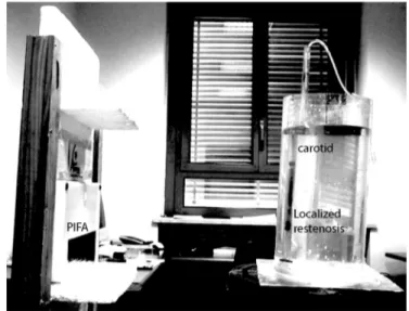
Fig. 9. Experimental set-up comprising the liquid phantom resembling the neck where the STENTag has been implanted, and the interrogation 5 dB patch antenna connected to the Thing-Magic M5e reader (not shown in the figure). The darker area in the central part of the phantom corresponds to the ISR. Such a volume is filled/emptied by means of a proper hydraulic circuit.
have been interconnected by means of crimped miniature con-nectors. Finally, the IC and the inductor have been insulated by a teflon tape (not shown in the figure) before the implant.
The STENTag has been experimented in vitro by means of equivalent liquid phantoms, according to the numerical model of Fig. 4. The larger and smaller cylinders have been fabricated by perspex pipes of thickness 2 mm and 1 mm, respectively, and then filled with liquid mixtures of water, sugar and salt which simulates the dielectric properties of the human tissues according to the recipes in [29]. The measured permittivity of the liquid phantoms, averaged over 6 samples, are indicated in Table I and compared with the expected values from the recipes. The diffuse proliferative ISR has been rendered by dividing the small pipe into three parts. The central one, wherein the STENTag is placed, is dynamically filled/emptied by means of a proper hydraulic circuit (Fig. 9).
All the measurements have been performed within the UHF band (840–960 MHz) by means of a UHF Thing-Magic M5e reader, connected to a 5 dB gain linear polarized patch antenna (Fig. 9) which is placed at 20 cm from the neck phantom, as in the simulations. The reader permits to control the input power by 0.5 dB steps and the receiving module performs a 8-bit digital conversion of the signals backscattered by the tag.
Fig. 10 shows the curves of the measured turn-on power in the UHF band, versus the change of permittivity of the liquid filling the STENTag. The curves have similar behavior but are clearly distinguishable. The power required to turn on the chip reduces as the stenosis’s grade gets worse. A nearly 3 dB dynamic range is observed at each frequency when moving from the healthy condition to complete plaque occlusion of the duct.
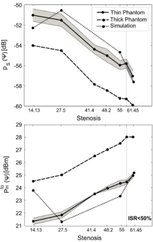
A more quantitative representation including the error anal-ysis and the comparison with the computer simulations at 870 MHz is given in Fig. 11 for both the backscattered power and the turn-on power . The mean value and the standard deviation (the gray region) have been calculated starting from
Fig. 10. Measured turn-on power in the UHF (World- Wide) Band for the STENTag prototype, versus the change of the liquid permittivity filling the carotid-like pipe.
Fig. 11. Measured (mean and shaded uncertainty region) and simulated (a) backscattered power and (b) turn on power for the STENTag prototype at 870 MHz, on varying the liquid composition inside the carotid-like phantom. The measured data are sorted according to the real part of the considered complex permittivity.
nine measurements at different angular offset (within ) be-tween the reader’s antenna and the tag.
First of all, it is apparent that in spite of the high tolerance in the fabrication of the tag and, non least, the typical instabil-ities of the receiving module of the RFID reader, simulations and measurements are in reasonable agreement, demonstrating
Fig. 12. Normalized scale factor of a) backscattered power and b) turn on power for the two phantoms, on varying the liquid composition inside the carotid-like pipe. The measured data are sorted according to the real part of the considered complex permittivity.
the possibility to master the sensing and the communication re-sponse of the implanted radio sensor by means of the proposed design methodology.
The sensitivity to the tag’s status is remarkable even in the early modification of the liquid, corresponding to an
% (from to ) with a monotonic behavior in the entire considered permittivity range. The turn-on measurement is al-most invariant with the observation angle with less than 0.5 dB uncertainty mainly due to the poor resolution of the reader. An even sharper sensitivity to the vessel’s change is finally found by the backscattering analysis, with approximately 5 dB span be-tween the healthy carotid and the full occlusion by plaque . The measurement variability of the backscattered power is instead not negligible, especially for extremely low values of
.
In order to analyze the sensibility of the proposed approach to the variability of the body district, the STENTag has been experimentally characterized also by considering a bigger neck phantom, resembling a stout subject. Such a phantom, referred to as thick phantom, is similar to the one in Fig. 4, except for the different diameter of the large cylinder ( cm) and for the position of the carotid-like pipe with respect to the border ( cm). The results (Fig. 11) are similar to those of the previous case except for a 3 dB scaling since the increased size of the phantom and the deeper position of the radio-sensor produce
TABLE II
MEASUREDRELATIVECHANGES IN THESTENTAGRESPONSES
a rise of the losses and consequently of the power required to establish the communication.
The uncertainty in the measured data may be however re-duced by using all the frequency domain data in Fig. 10 and introducing an averaging operator over frequency. It is hence defined a normalized scale factor:
(12) where the “ ” brackets indicate the average over frequency
samples and . Fig. 12 shows the averaged
and for the two phantoms. For clarity only the standard deviation of the thin case is presented. Since is a relative parameter, the profiles of the two phantoms are almost over-lapped, demonstrating the repeatability of the sensing measure-ment regardless the human variability. Moreover the use of an averaging indicator sensibly reduces the uncertainty of the data, when compared to Fig. 11. In the worst case the uncertainty is only the 3% of the mean value, while in the early grade of the restenosis % it drops to less than 1.5%.
Finally, by a linear fitting of the curves in Figs. 11 and 12, it is possible to estimate the percentage variation of all the pre-vious power indicators referred to the healthy state (Table II). In particular, a remarkable 33% of variation of the STENTag response may be achieved in the early restenosis
by monitoring the changes of the normalized scale factor of the backscattered power and more than 3 times changes at the atherosclerotic restenosis .
IV. CONCLUSION
Numerical analysis and early experimentation seem to cor-roborate the possibility to sense some inner biological processes by means of implanted passive RFID tags. These phenomena in evolution produce specific and macroscopic effects on the elec-tromagnetic response of the radio-sensor, which are detectable by the available low-cost technology and with limited power budgets (maximum radiated power less than 1 EIRP), making feasible to embed the required reader capability inside an hand-held device and even into a smartphone.
Tag design may benefit from various degrees of freedom: the sensitivity of the radio-sensor can indeed be enhanced by using high impedance ICs, while the inversion curves, relating the ex-pected tag response to the change of the physical phenomena, may be shaped by a wise selection of the impedance matching condition.
The RFID interrogation provides two independent measure-ments: turn-on power and the backscattered power which, if observed over the frequency, may provide really robust and monotonic metrics, rather immune to the specificity of patients and to the measurement modality. For the considered applica-tion to the STENTag problem, the achieved sensing capabilities
look enough to fully discriminate the early grade of restenosis % by about a 40% variation in the mea-sured data.
The described design technique may be however straightfor-wardly extended to many other implanted metal devices, such as prosthesis, sutures, graft or orthopedic fixings, for which long-term monitoring may provide an added value and turn the pa-tient itself into a primary hub in the emerging personal health-care systems.
ACKNOWLEDGMENT
This work was developed under project PRIN-2008: MULTI-TAG funded by Italian Ministry of University. The authors wish to thank Prof. L. De Medici of the Radiology Department of San Camillo Hospital, Roma, for inspiration and discussions.
REFERENCES
[1] G. Marrocco, L. Mattioni, and C. Calabrese, “Multi-port sensor RFIDs for wireless passive sensing-basic theory and early simulations,” IEEE
Trans. Antennas Propag, vol. 56, no. 8, pp. 2691–2702, Aug. 2008.
[2] A. Sani, M. Rajab, R. Foster, and Y. Hao, “Antennas and propagation of implanted RFIDs for pervasive healthcare applications,” Proc. IEEE, vol. 98, no. 9, Sep. 2010.
[3] A. Alomainy and Y. Hao, “Modeling and characterization of biotele-metric radio channel from ingested implants considering organ contents,” IEEE Trans. Antennas Propag., vol. 57, no. 4, pt. 1, pp. 999–1005, Apr. 2009.
[4] F. Merli, B. Fuchs, J. R. Mosig, and A. K. Skrivervik, “The effect of insulating layers on the performance of implanted antennas,” IEEE
Trans. Antennas Propag., vol. 58, no. 1, pp. 21–31, 2011.
[5] W. Xia, K. Saito, M. Takahashi, and K. Ito, “Performances of an im-planted cavity slot antenna embedded in the human arm,” IEEE Trans.
Antennas Propag., vol. 57, no. 4, pt. 1, pp. 894–899, Apr. 2009.
[6] [Online]. Available: http://www.positiveidcorp.com/
[7] E. Y. Chow, C.-L. Yang, O. Yuehui, A. L. Chlebowski, P. P. Irazoqui, and W. J. Chappell, “Wireless powering and the study of RF propa-gation through ocular tissue for development of implantable sensors,”
IEEE Trans. Antennas Propag., vol. 59, no. 6, pp. 2379–2387, Jun.
2011.
[8] D. Valderas, C. Schmidt, and X. Chen, “Broadband implanted UHF RFID antenna,” in Proc. IEEE Antennas and Propagation Society Int.
Symp. (APSURSI), Toronto, 2010, pp. 1–4.
[9] H. Rajagopalan and Y. Rahmat-Samii, “Ingestible RFID bio-capsule tag design for medical monitoring,” in Proc. IEEE Antennas and
Prop-agation Society Int. Symp. (APSURSI), Toronto, 2010, pp. 1–4.
[10] M. Bitzer, T. Nagele, B. Geist-Barth, U. Klose, E. Gronewaller, M. Morgalla, E. Heiss, and K. Voigt, “Role of hydrodynamic processes in the pathogenesis of peritumoral brain edema in meningioma,” J.
Neu-rosug, vol. 39, no. 4, pp. 594–604, Oct. 2000.
[11] J. L. Schepps and K. R. Foster, “The UHF and microwave dielectric properties of normal and tumor tissues: Variation in dielectric proper-ties with tissue water content,” Phys. Med. Biol., vol. 25, no. 6, pp. 1149–1159, 1980.
[12] A. P. O’Rourke, M. Lazebnik, J. M. Bertram, M. C. Converse, S. C. Hagness, J. G. Webster, and D. M. Mahvi, “Dielectric properties of human normal, malignant and cirrhotic liver tissue: In vivo and ex vivo measurements from 0.5 to 20 GHz using a precision open-ended coaxial probe,” Phys. Med. Biol., vol. 52, no. 15, pp. 4707–4719, Aug. 2007.
[13] R. Hoffmann, G. S. Mintz, G. R. Dussaillant, J. J. Popma, A. D. Pichard, L. F. Satler, K. M. Kent, J. Griffin, and M. B. Leon, “Patterns and mechanisms of in-stent restenosis, a serial intravascular ultrasound study,” Circulation, vol. 94, pp. 1247–1254, 1996.
[14] M. Habara, M. Terashima, K. Nasu, Y. Kinoshita, E. Tsuchikane, Y. Asakura, O. Kato, and T. Suzuki, “The morphological findings of very late in-stent restenosis after bare-metal stent implant: Optical coher-ence tomography analysis,” Circulation, vol. 122, p. A11302, 2010. [15] Handbook of Coronary Stents, P. W. Serruys and B. Rensing, Eds., 4th
[16] P. V. Nikitin and K. V. S. Rao, “Theory and measurement of backscat-tering from RFID tags,” IEEE Antennas Propag. Mag., vol. 48, no. 6, pp. 212–218, Dec. 2006.
[17] G. Marrocco, E. Di Giampaolo, and R. Aliberti, “Estimation of UHF RFID reading regions in real environments,” IEEE Antennas Propag.
Mag., vol. 51, pp. 44–57, 2010.
[18] G. Marrocco, “The art of UHF RFID antenna design: Impedance-matching and size-reduction techniques,” IEEE Antennas Propag.
Mag., vol. 50, no. 1, pp. 66–96, Feb. 2008.
[19] C. Gabriel and S. Gabriel, “Compilation of the dielectric properties of body tissues at RF and microwave frequencies,” [Online]. Available: http://niremf.ifac.cnr.it/docs/DIELECTRIC/home.html
[20] K. V. S. Rao, P. V. Nikitin, and S. F. Lam, “Impedance matching con-cepts in RFID transponder design,” in Proc. 4th IEEE Workshop on
Automatic Identification Advanced Technologies, 2005, pp. 39–42.
[21] G. Marrocco, “RFID antennas for the UHF remote monitoring of human subjects,” IEEE Tran. Antennas Propag., vol. 55, no. 6, pp. 1862–1870, Jun. 2007.
[22] A. A. El-Menyar, J. A. Suwaidi, and D. R. Holmes, Jr, “Use of drug-eluting stents in patients with coronary artery disease and renal insuf-ficiency,” Mayo Clinic Proc., vol. 85, no. 2, pp. 165–171, Feb. 2010. [23] B. K. Lal, E. A. Kaperonis, S. Cuadra, I. Kapadia, and R. W. Hobson
II, “Patterns of in-stent restenosis after carotid artery stenting: Classifi-cation and impliClassifi-cations for long-term outcome,” J. Vasc. Surgery, vol. 46, no. 5, pp. 833–840, Nov. 2007.
[24] Cordis PRECISE Nitinol Stent System [Online]. Available: http://www.cordislabeling.com
[25] E. Y. Chow, Y. Ouyang, B. Beier, W. J. Chappell, and P. P. Irazoqui, “Evaluation of cardiovascular stents as antennas for implantable wire-less applications,” IEEE Trans. Microw. Theory Tech., vol. 57, no. 10, pt. 2, pp. 2523–2532, Oct. 2009.
[26] L. Sheddena, S. Kennedyb, R. Wadsworthc, and P. Connollyd, “To-wards a self-reporting coronary artery stent—measuring neointimal growth associated with in-stent restenosis using electrical impedance techniques,” Biosen. Bioelectron., vol. 26, pp. 661–666, 2010. [27] Boston Scientific Carotid WALLSTENT [Online]. Available: www.
bostoscientific.com
[28] Visible Human Project [Online]. Available: http://www.nlm.nih.gov/ research/visible/visible_human.html
[29] G. Hartsgrove, A. Kraszewsky, and A. Surowiec, “Simulated biolog-ical materials for electromagnetic radiation absorption studies,”
Bio-electromagnetics, vol. 8, no. 4, pp. 29–36, 1987.
Cecilia Occhiuzzi (M’12) received the M.Sc. degree
in medical engineering and the Ph.D. in electromag-netics from the University of Rome “Tor Vergata”, in 2008 and 2011, respectively.
Currently, she is a Research Assistant in the University of Rome “Tor Vergata”, with interests in wireless health monitoring by means of wear-able and implantwear-able radiofrequency identification techniques. In 2008, she was with the School of En-gineering, University of Warwick, Warwick, U.K., as a postgraduate student involved with design and
implementation of wireless surface acoustic wave (SAW) sensors. In 2010, she was a Visiting Researcher with the Georgia Institute of Technology, Atlanta. Her research was mainly focused on the design of passive RFID sensors for structural health monitoring and gas detection by means of CNT-based tags. She holds two patents on sensor RFID systems.
Giordano Contri received the M.Sc. degree in
med-ical engineering from the University of Rome “Tor Vergata”, in 2010 and is currently working toward the Ph.D. degree.
His main research interests concern implantable RFID antennas with sensing capabilities. He is working in COSMED (pulmonary function equip-ment) and is involved in R&D projects for innovative telemetric devices.
Gaetano Marrocco (M’12) was born on August 19,
1969, in Teramo, Italy. He received the Laurea de-gree in electronic engineering and the Ph.D. dede-gree in applied electromagnetics from the University of L’Aquila, Italy, in 1994 and 1998, respectively.
He has been a Researcher at the University of Rome “Tor Vergata” since 1997 where he currently teaches antenna design and bioelectromagnetics. In summer 1994, he was at the University of Illinois at Urbana Champaign, as a Postgraduate Student. In autumn 1999, he was a Visiting Scientist at Imperial College in London. His research is mainly directed to the modelling and design of broadband and ultrawideband antennas and arrays as well as of miniaturized antennas for RFID applications. He has been involved in several space, avionic, naval and vehicular programs of the European Space Agency, NATO, Italian Space Agency, and the Italian Navy. He holds two patents on broadband naval antennas and one patent on sensor RFID systems.
Prof. Marrocco currently serves as an Associate Editor of the IEEE Antennas