DOTTORATO DI RICERCA IN
Meccanica e scienze avanzate dell’Ingegneria
Ciclo XXIX
Settore Concorsuale di afferenza: 09/A1 Settore Scientifico disciplinare: ING-IND/04
TITOLO TESI
Experimental and Numerical Evaluation of
Impact Damage Tolerance in composite materials
Presentata da: Falaschetti Maria Pia
Coordinatore Dottorato
Relatore
Prof. Nicolò Cavina
Prof. Ing. Enrico Troiani
Index
Introduction . . . I Chapter 1: Damage Tolerance: Aeronautics requirements . . .1.1 Hystory of airplane design development . . . 1.2 Damage Tolerance phylosophy. . .
1.2.1 Damage Tolerance design . . . 1.2.2 Ageing structures . . . 1.3 Composite Aeronautics regulations . . . 1.3.1 Airworthiness Regulations . . . 1.3.2 Regulation applications . . . 1.3.3 No-Growth Concept . . . 1 1 5 6 8 10 10 12 13 Chapter 2: Impact on aerospace structure . . .
2.1 Impact on airframes . . . 2.2 Impact on space structures . . . 2.3 Impact causes . . . 2.4 Impact damages . . . 2.5 Low-velocity impacts . . . 17 17 21 22 23 24 Chapter 3: Experimental Impact tests . . .
3.1 Impact tests . . . 3.2 Low Velocity Impact tests . . .
3.2.1 Charpy pendulum . . . 3.2.2 How to use ‘modified pendulum’ at Unibo (MasterLab)
laboratories . . . 3.2.3 Accelerometer acquisitions . . . 29 29 31 33 35 37 Chapter 4: Compression After Impact (CAI) tests . . .
4.1 Compression tests on composite materials . . . 4.1.1 Shear loaded . . . 4.1.2 Sandwich-Beam Compression Test Method . . . 4.1.3 End-loaded Test Method . . . 4.1.4 Shear and end-loading Test Method . . .
43 44 45 46 48 49
4.2.2 Boeing CAI Fixture . . . 4.2.3 BAE Systems CAI Fixture . . . 4.2.4 Airbus CAI Fixture . . . 4.3 CLC tests at ENEA Laboratory of Materials Technologies Faenza . . 4.4 Post-processing data . . . 50 50 51 52 58 Chapter 5: Experimental campaign on carbon/epoxy coupons . . .
5.1 Carbon/epoxy coupon experimental campaigns. . . 5.1.1 Manufacturing of specimens . . . 5.2 Impact tests . . . 5.3 CAI tests . . . 5.4 Thin specimens experimental campaign . . .
5.4.1 Impact tests . . . 5.4.2 Compression After Impact . . . 5.5 Thick specimens experimental campaign . . .
5.5.1 Impact tests . . . 5.5.2 Compression After Impact . . . 5.6 Overall conclusions . . . 61 61 62 66 66 67 67 68 70 70 73 74 Chapter 6: History and development of Fibre Metal Laminate . . .
6.1 Introduction . . . 6.2 Fibre Metal Laminate (FML) . . .
6.2.1 History . . . 77 77 78 79 Chapter 7: Experimental campaign on Fibre Metal Laminate . . .
7.1 FML experimental campaign . . . 7.1.1 Specimens . . . 7.2 Tests . . . 7.2.1 DIC . . . 7.2.2 Results . . . 7.3 Discussion . . . 85 85 85 97 97 99 109 Chapter 8: FEM analysis: Cohesive Zone Model . . .
8.1 Introduction . . . 8.2 Model overlook . . . 8.3 Cohesive zone model . . .
111 111 112 113 Chapter 9: FEM analysis: Impacts on Carbon/Epoxy and FML coupons
9.1 Carbon/epoxy developed model. . . 9.1.1 Impactor geometry and characteristics . . . 9.1.2 Laminate geometry and characteristics . . .
119 119 119 121
9.1.4 Boundary conditions . . . 9.1.5 Results . . . 9.2 FML developed model . . .
9.2.1 Impactor geometry and characteristics . . . 9.2.2 Laminate geometry and boundary conditions. . . 9.2.3 Mesh . . . 9.2.4 Results . . . 9.3 Overall discussion . . . 123 125 139 140 141 142 142 152
Conclusions and future research . . . 155
Acknowledgement . . . 159
Appendix A: Carbon/Epoxy specimens dimensions . . . i
-I-
Introduction
Composite materials have always been part of humankind history, but only with industrial application, a deep improvement was obtained. Since ‘70s, advanced composite materials were introduced in many fields: aerospace, aeronautics, automotive, sports, etc. Different kinds of resins and fibres were studied and developed, in order to achieve several aims and to take advance of the most important composites usefulness, i.e. their adaptability to various load and structure conditions.
At the same time, however, composites drawbacks were acknowledged: due to their ‘multiple’ nature, load bearing, damage evolutions and external environment influence, are completely far from metal materials, which have been studied for ages. Therefore, aerospace and aeronautic industry, due to the necessity of lighter and safer structures, started a deep research on composite behaviour under operative conditions to be able to overcome material issues.
Aeronautic field is mostly interested in Polymer Matrix Composites due to their high strength, high stiffness, fatigue resistance, low weight and corrosion resistance. In particular, their better strength to weight ratio, compared to metals (Figure 1-2), is probably the main reason that boosted their application.
Many studies were performed to better understand composite mechanical characteristics and their response to operative environment. This allowed this kind of material usage in wide sections of airplane structures, where, as known, safety is the most important issue for builders (Figure 3-4).
Only few characteristics are still unknown and, therefore, safety factors higher, than those theoretically necessary, are needed. In particular, predicting composite vulnerability to an impact is a major issue. Many events could cause an impact on an aeronautic structure: bird strike, hail, luggage loading, handling service, etc. Each one of these causes results in a different kind of impact and a damage more or less detectable (Figure 5).
-II-
Figure 1: materials strength and Young moduli values referring to density
Figure 2: comparison between metals and composites fatique characteristics
-III-
Figure 4: Airbus A350: material content by weight
Figure 5: Different kinds of impact and structure residual strength
The most dangerous impact kind is the low energy impact: it could result in no damage evidence on the impacted surface, creating a wide damage inside the laminate. Therefore, there could be a reduction of structure characteristics, leading to a catastrophic failure before any evidence appears on external surface.
Hence, a better understanding on composite response to impact event and their after impact characteristics is necessary.
-IV-
Principal aim of this PhD work was to develop a deeper comprehension of CFRP (Carbon Fibre Reinforced Plastic) behaviour under dynamic loads. Therefore, experimental and numerical results, of three years research, will be presented.
In particular:
Chapter 1 presents a brief introduction to Damage Tolerance design concept. This is the most advanced design criteria developed in aeronautic: it treasures all lessons learned from past airplane accidents and it is open to new raising concept, in order to create better structures. An example are guiding rules applied to composites; there is not a strict written path: beside safety requirements, industries are free to develop their internal methodologies and this is a good way to achieve a wider understanding of composites characteristics.
Chapter 2 concentrates on impact issues in aerospace fields, with particular attention to its interest development through aerospace and aeronautic history. Principal composite damages are described, focusing on low velocity impact damages.
Chapter 3 describes impact test method designed and realised at Hangar Laboratories of University of Bologna in Forlì. Charpy pendulum concept has been studied and modified to achieve low velocity impact tests and, therefore, Barely Visible Impact Damage (BVID). Chapter 4 describes all Compression After Impact (CAI) and composite compression tests fixtures, with particular attention to Combined Loading Compression test Fixture that was used for all experimental campaigns performed in this PhD research.
Chapter 5 shows results from two experimental campaigns, regarding low energies impacts and BVID on carbon/epoxy composite laminate. First campaign involves 2.6 mm thick specimens while the second one is related to 5.5 mm thick specimens, giving opportunity to compare thickness influence of impact damages on residual compressive strength.
Chapters 6 and 7 focus on research work done during stay at TU Delft University. Trying to find an improvement for composite impact resistance, research led to Fibre Metal Laminate study. Therefore, taking the chance to be at the University which developed this kind of material, a deeper study related to aluminium layers position inside a stacking sequence was carried out. Quasi Static Indentation tests were performed and results are presented.
Chapter 8 is a brief introduction to Finite Element Theory, in particular to cohesive element theory, while Chapter 9 illustrates FE Model and results regarding simulations of impacts on carbon/epoxy and FML coupons that have been developed.
- 1 -
1
Damage Tolerance:
Aeronautics requirements
In this first chapter, after a brief history related to aeronautic requirements evolution, an introduction to Damage Tolerance philosophy is presented; in particular, composites regulations and application of No-Growth concept are described.
1.1 Hystory of airplane design development
Building airplanes has always been a difficult issue for who wanted to achieve fly. Many difficulties were faced by researchers but it was an interesting challenge: the first important proof of flying machines can be found during Renascence, in particular in 1485 when Leonardo da Vinci studied one of the first ornithopters and the first example of helicopter (Figure 1.1).
Figure 1.1: Leonardo da Vinci’s ornithopter and helicopter
Other attempts were made but no one could really achieve this goal before Wright brothers. They tried many times before the day that is still considered the first flight of a motorized airplane controlled by a pilot: 17th December 1903. The Wright Flyer (Figure
- 2 -
1.2) is still considered the first airplane and it marks the beginning of modern airplanes history, even for what is related to resistance, reliability and endurance tests.
Figure 2.2: Wright Flyer
Those first airplanes were made with wood and canvas but only static tests were performed. Operative life or fatigue damages were not taken into account. An example is given by Fokker airplanes used during First World War (Fokker E.III, Fokker Dr.I, Fokker D.VII). For Fokker industry founder, Dutch pioneer and industrialist Antony Fokker, fatigue does not occur in seasoned wood. Nowadays it is well known that this is not true, and that fatigue is a structural phenomenon. But back in twenties, when airplanes were a new concept, seen as new weapon, and therefore used only during war, there was not any chance to actually develop fatigue damages.
During thirties, metal materials were introduced together with Safe-Life design concept. Structure Safe-life represents the number of events (such as flights, landings, or flight hours) during which probability to have a reduction of strength, under its design ultimate value, due to fatigue cracking, is very low.
Hence, it is assumed that fatigue failure is not going to occur during structure life and after this period the element is completely replaced by a new one (Safety-by-retirement). In that era, this approach still worked due to quite short airplanes operative life (caused by external factors); but when for economic reasons there was need for longer design lives, materials used where substituted with stronger alloys and, for a lower fuel consumption, higher altitudes were preferred. Hence, fatigue problems started and, with them, the necessity to change regulations.
The main event that made this necessity evident was the double accident of two Comet planes in 1954: those two airplanes were designed with Safe-Life concept and they crushed after 1286 and 903 flights due to a crack started from a window corner and propagated really fast, resulting in a fuselage explosion at cruise altitude. During design, full scale tests were performed and fatigue cracks were found after 16000 flights, so
- 3 -
accidents were totally unexpected after so lower number of flights; this was caused by an un-conservative way of testing: for fatigue tests was used the same airplane used before for static tests. Therefore, during static testing local plasticity was reached and this created a barrier for fatigue cracks growth under cyclic loads, resulting in a longer fatigue life than that of a really new airplane.
Hence, Fail-Safe methodology was therefore introduced: Fail-Safe is the attribute of the structure permitting to bear required residual strength for a period of un-repaired use even after failure or partial failure of a principal structural element. This means that, even with a fatigue or other cause damages, airplane has to safely bear flights loads: this kind of concept is also called Safety-by-design and it is achieved with ‘multiple structural member concept’ that consists of having redundancy of principal structures. But unfortunately, even this design method was not enough to prevent other accidents: first of all, a proper inspection plan is not defined and moreover there is not any concept of pre-existed flaws. Finally, due to economic reasons, airplanes later started to be used for very long time (longer than their design retirement period) and with Fail-Safe there was not any reference to aged planes.
In 1973 a F111 crashed due to the failure of one of its wings caused by growth of an initial flaw. This event demonstrated that assuming structures perfect when new, is completely un-real. Lately, in 1977 in Lusaka an airliner lost its entire horizontal stabilizer after it being redesigned for a higher take-off weight (from a passenger airliner it became a cargo one). This accident was caused by a fatigue crack in upper spar cap at bolt hole that was not detected due to not proper inspections and warnings for high bolt loads not taken into account. Other aged airplanes lately showed the same kind of cracks and they were also reproduced by full scale tests, that were not performed before releasing airplane.
These two accidents demonstrated which weak points were in Fail-Safe concept and led to a new design method: Damage Tolerance. With this term, it is called the ability of the structure to sustain anticipated loads in the presence of damage (due to fatigue, corrosion or external events) until it is detected through inspections or malfunctions and it is repaired.
Hence, with this methodology imperfections are assumed to be present even in new pieces, inspectability needs to be assured, inspections plans are defined and structures have to bear load until fatigue, corrosion or impact damages are detected and repaired (Safety-by-inspections). It is worth to notice that with Damage Tolerance introduction, the other concepts are not replaced: there still are structures that cannot be designed following DT requirements and therefore are designed under Safe-Life or Fail-Safe methods (Figure 1.3).
- 4 -
Unfortunately, there was need to another accident to learn another aspect that DT did not take into account until 1988. That year a Boing 737 of Aloha airline succeeded in landing with a large part of upper fuselage missing. This was caused by ‘Multiple Site Damage’, i.e. many different cracks nucleated in different locations (in this case around riveted joints) grew and got connected all together resulting in a huge damage and in catastrophic failure. The cause of this was placed in insufficient inspections in relation with the operative environment where that airplane was flying: Hawaii islands with a flight period of 45 min per flight, so short ground-air-ground cycles in a warm, humid and salty environment. That kind of conditions accelerated MSD growth in cold bond/riveted lap joints: bond was damaged and it could not bear load anymore, transferring all of that to rivets creating stress concentrations and hence multiple fatigue damages.
- 5 -
After this accident, Widespread Fatigue Damage concept was introduced in regulation; in particular, they were acknowledged two different concepts: Multiple Site Damage, when there are many cracks in the same structural element, and Multiple Element Damage, when cracks are present within similar adjacent elements. The importance of these two new concepts introduction is very clear analysing Delta Boing 727 MSD discovery: during pre-flight walk around, pilots noticed two cracks growing under a lap joint; disassembly the joint, a 500mm long crack was discovered. This was a lucky case that prevented a probable catastrophic failure and many fatalities to occur.
1.2 Damage Tolerance phylosophy
Aeronautical design laws take into account many different perspectives:
- undamaged structure static resistance: structure must bear ultimate load (UL) for 3 sec, without any failure;
- undamaged structure deformation: there must not be any everlasting deformation if structure is loaded under Limit Load (LL) and, if there is any at LL, this must not affect flight safeness;
- fatigue crack nucleation in an undamaged structure: Damage Tolerance parts must satisfy durability requests while Safe Life parts must be pristine until the end of their operative lives;
- fatigue crack growth in damage structure: for DT parts inspection plans and NDI techniques must be well set up to reduce catastrophic failures;
- damaged structure static residual strength: damage structures must bear LL without any catastrophic failure.
Here a deeper description of Damage Tolerance philosophy, related to the last three points and more affecting design costs and airplanes safeness.
As already said, aeronautic structures face hard operative conditions and are subjected to complex load cycles. These affect considerably their durability and mechanical characteristics: cyclic loads could create new cracks or accelerate already existing damages (due to flaws in the material or caused by accidental impacts) growth. It is, hence, necessary to know static resistance of a damaged structure. This is defined as Residual Strength (RS) and it takes into account actual damage evolution during operative life. During structure operative life, in fact, due to loads or external parameters, cracks tend to growth with different rates decreasing Residual Strength.
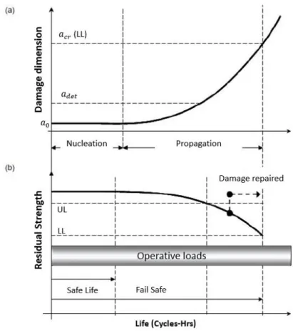
The DT philosophy is presented, in short, in Figure 1.4:
- an initial damage is considered already present in the structure, even if NDI (Non Destructive Inspection) has not find any out; it is considered equal to the smallest NDI sensitivity, i.e. the smallest damage detectable (𝑎0);
- 6 -
- minimum detectable damage size (during inspections) is indicated with 𝑎𝑑𝑒𝑡; - structure Residual Strength decreases with damage growth: it is necessary,
therefore, to detect damage before its size is equal to 𝑎𝑐𝑟 (critical damage size), where RS reaches LL values; detecting and repairing damage before reaching 𝑎𝑐𝑟, it is possible to bring RS back to higher values and, hence, far from catastrophic failure chances.
Figure 1.4: Damage Tolerance design graphs: (a) crack growth,
(b) residual strength, both referring to fatigue loads cycles
1.2.1 Damage Tolerance design
Fatigue and Damage Tolerance requirements are listed into part 25 of Section 571 of European Joint Airworthiness Requirements (JAR) and of American Federal Aviation Regulation (FAR) [1.1].
It is required that, each Principal Structural Element (PSE) must be identified and designed following DT philosophy due to their contribution to load bearing and airplane safety. An Inspection plan must be developed per each PSE in order to detect damages and repair them as soon as possible, before critical dimensions are reached.
As already said, if inspections are not possible (due to part position or inspections frequency is too high), it is necessary to follow Safe Life design approach. Hence, it is defined part operative life (Design Service Goal), in which no damages should nucleate.
- 7 -
At the end of this DSG, that part is substituted. This design concept is more expensive than DT due to higher safety factors applied and high rate of waste (when a piece is substituted, is cannot be used again) (Figure 1.5).
Figure 1.5: Damage Tolerance Design [1.3]
Ergo, as showed in Figure 1.1, if it is not possible to have inspection on an airplane part, this must be designed as Safe Life. If inspection is possible, Slow Crack Growth needs to be proved.
Slow Crack Growth concept is applied on those structure were load has to follow a single path, i.e. there is no other way to share that load and, therefore, any damage tends to growth only on that part. This philosophy says that, during airplane design, all precautions, related to geometry and materials, must be applied in order to obtain a crack growth as slow as possible. This leads to a longer time for damage detection without safe issues. In this way, supposing a pre-existent flaw, inspection plan is obtained dividing structure Crack Growth Life, i.e. number of cycles or flight hours for a damage to growth from 𝑎𝑑𝑒𝑡 to 𝑎𝑐𝑟, by a Safety Factor. The latter is function of many factors but usually it is around 2÷3.
When Slow Crack Growth cannot be demonstrated, other aeronautic concept is needed: Fail Safe. This philosophy is based on three principles:
- Redundancy: even if a structure fails, there is another one carrying out the same aim;
- Multi Load Path structures: loads are spread out between more ways in order to, if one of them is stopped due to a damage, others can keep carrying out loads; - Crack Arrest structures: thanks to materials or geometry they oppose against
- 8 -
Therefore, a Fail-Safe structure is able to bear loads even if badly damaged, until inspections (that, hence, can be more relaxed). In fact, in the Advisory Circular 25.571, it is referred as: “Fail-Safe is the attribute of the structure that permits it to retain its required residual strength for a period of unrepaired use after the failure or partial failure of a principal structural element”.
1.2.2 Ageing structures
It is worth to notice that the described design criteria count for new airplanes: as already said, in fact, airplanes are designed for satisfy their Design Service Goal, i.e. a certain operative life span, but due to economical requests and aged airplane still good conditions, it was request to make them flight in safety a little longer. Hence, development of new line guides for aging airplanes [1.1].
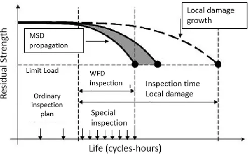
Main issue is Widespread Fatigue Damage (WFD), i.e. contemporaneous presence of many damages. This could be Multiple Site Damage (MSD) or Multiple Element Damage (MED) (Figure 1.6).
Figure 1.6: Multi Site Damage and Multiple Element Damage [4]
Multiple Site Damage happens when damages are on the same part and are geometrically similar carrying quite similar loads, e.g. riveting holes. Due to same driving force, fatigue cracks could nucleate and grow contemporary and, if cracks are close to each other, they could connect themselves and create a long crack, leading to a catastrophic failure way faster than a new structure (Figure1.7-1.8). Moreover, due to MSD, Crack Growth life is also shortened and more frequent inspections need to be performed. This could be not enough [1.5]; the only expedient to avoid dangerous situations is to design every airplane for avoiding WFD in all its operative life (Advisory Circular (AC) AC25.571-1C [1.1]), reducing load intensity in those areas where WFD could take place (‘Damage Tolerance was not intended as a safety management tool for structures operating beyond their initial design life goals or beyond the point where WFD is likely to occur’, [1.2].
- 9 -
Figure 1.8: Smaller inspection gap due to smaller critical damage with MSD
In conclusion, nowadays, Damage Tolerance concept is obviously the most important and developed criteria that could be applied in airplane design. On the other hand, many things need to be sharpened a little more to obtain even safer requirements with a better usage of structures and materials.
It is worth to say that Damage Tolerance requirements do not put any limits on how to achieve them. Therefore, each industry can develop its own methods to build up safe and long lasting airplanes, even developing new and higher thresholds.
- 10 -
1.3 Composite Aeronautics regulations
Previously presented regulations are principally related to metallic materials. Advanced composite materials were introduced in the last thirty years and, due to their complexity and unpredictability, many operative behaviours are still unknown. Therefore, Airworthiness Regulations related to this kind of materials leaves more freedom to industries, pointing attention mostly on safety and damage ‘no-growth’ concept. In particular, peculiar wariness is granted to accidental damage during service life. In the following sections requirements are reported from original regulation documentations [8].
1.3.1 Airworthiness Regulations
Static requirements (EASA certification Basis [1.8] Sec. 25.305)
Sec 25.305 (a): “The structure must be able to support limit loads without detrimental permanent deformation. At any load up to limit loads, the deformation may not interfere with safe operation.”
Sec 25.305 (b): “The structure must be able to support ultimate loads without failure for at least 3 seconds. However, when proof of strength is shown by dynamic tests simulating actual load conditions, the 3-second limit does not apply.”
Damage Tolerance and Fatigue requirements (EASA certification Basis [1.8] Sec. 25.571)
Sec 25.571 (a): General "An evaluation of the strength, detail design, and fabrication just show that catastrophic failure due to fatigue, corrosion or accidental damage will be avoided throughout the operational life of the aeroplane. (…) Inspections or other procedures must be established as necessary to prevent catastrophic failure (…)" Sec 25.571(b): Damage Tolerance (Fail-Safe) evaluation "The evaluation must include a determination of the probable locations and failure modes due to fatigue, corrosion, or accidental damage." (…) "The extent of damage for residual strength evaluation at any time within the operational life must be consistent with the initial detectability and subsequent growth under repeated loads. The residual strength evaluation must show that the remaining structure is able to withstand loads (considered as ultimate static loads) corresponding to the following conditions (…)".
Acceptable Means of Compliance (AMC, non-inding guides used to transpose regulations into really applicable characteristics)
- 11 -
Sec 25.603 - 5: Proof of structure – Static
§ 5.3: "Static strength structural substantiation tests should be conducted on new structure unless the critical load conditions are associated with structure that has been subjected to repeated loading and environmental exposure. In this case either:
a) the static test should be conducted on structure with prior repeated loading and environmental exposure, or
b) Coupon/Element/Subcomponent test data should be provided to assess the possible degradation of static strength after application of repeated loading and environmental exposure and this degradation accounted for in the static test or in the analysis of the results of the static test of the new structure."
§ 5.8: "It should be shown that impact damage that can be realistically expected from manufacturing and service, but not more than the established threshold of detectability for the selected inspection procedure, will not reduce the structural strength below ultimate load capability."
Sec 25.603 – 6: Proof of structure – Fatigue/Damage Tolerance
§ 6.1: "(…) the following considerations are unique to the use of composite material systems and should be observed for the method of substantiation selected by the applicant. When selecting the damage tolerance or safe life approach, attention should be given to geometry, inspectability, good design practice, and the type of damage/degradation of the structure under consideration."
§ 6.2 Damage Tolerance (Fail-Safe) Evaluation
§ 6.2.1: "Structural details, elements, and subcomponents of critical structural areas should be tested under repeated loads to define the sensitivity of the structure to damage growth. This testing can form the basis for validating a no-growth approach to the damage tolerance requirements. (…)"
§ 6.2.2: "The extent of initially detectable damages should be established and be consistent with the inspection techniques employed during manufacturing and in service. (…)"
- 12 -
§ 6.2.3: "(…) the evaluation should demonstrate that the residual strength of the structure is equal to or greater than the strength required for the specified design loads (…). For the no-growth concept, residual strength testing should be performed after repeated load cycling."
§ 6.2.4: "An inspection program should be developed (…). For the case of no-growth design concept, inspection intervals should be established (…). In selecting such intervals the residual strength level associated with the assumed damage should be considered."
§ 6.2.6: "The effects of temperature, humidity, and other environmental factors (…) should be addressed in the damage tolerance evaluation."
1.3.2 Regulation applications
Due to difficulty in real application of previously reported regulations, they need to be interpreted.
In particular, for static requirements, paragraph 25.603-§5.8 defines two thresholds: the first is ‘threshold detectability for in service inspection procedures’ and it is called BVID (Barely Visible Impact Damage), while the second refers to the highest impact energy that could occur during production or service operations. A damage structure must be able to bear Ultimate Load under these thresholds.
In Damage Tolerance perspective, a damage that is outside static requirements must not lead to a catastrophic failure. Two different threshold are defined to describe DT domain: first corresponds to easily detectable damages, i.e. Large Visible Impact Damage (LVID), while energy threshold is linked to a probability of occurrence, usually around 10-9 per fight hours (fh). Within these limits, structure must maintain at least Limit Load (LL). Just below them, a damaged structure must carry out a load that is equal to 𝑘 ∗ 𝐿𝐿, where 1 < 𝑘 < 1.5.
Probability value is calculated by means of a statistical analysis of in service damages had those have occurred. This led to an empirical formula that links energy level with its probability of occurrence:
(1.1) 𝑝𝑖 (𝐸 ≥ 𝐸𝑖) = 10−𝑥
𝐸𝑖 15
With 𝑥 equal to 3.
Impact probability is, therefore:
- 13 -
(1.3) 𝑝𝑖 (𝐸 ≥ 90𝐽) = 10−9/𝑓ℎ
These equations have a general meaning: they need to be adapted for each aircraft location. In fact, as it will be presented in the following Chapter, different location on an aircraft has different impact probability with different energy level.
Figure 1.9: DT thresholds requirements
Hence, composite DT philosophy could be represented in Figure 1.9. For thick composite structures a cut-off energy criterion takes place (high impact energies that could heavily damage the structure) while for thin composite there is the detectability threshold. In the latter case, inspection plans are calculated by means of probabilistic study and intervals are usually small in order to avoid possible criticalities. This threshold does not refer to visible damages (low energy impacted do not produce visible damage but it can result in an internal failure). Therefore, it is important that structures are able to support effortlessly Limit Load.
1.3.3 No-Growth Concept
For composite structures, damage No-Growth theory is really important. It says that in a composite structure, under static or fatigue loads, there should be not any damage propagation and, even if the structure is damaged, it must be able to carry out loads. Moreover, new damages are not allowed to be created and structure strength must stay constant.
- 14 -
An airframer, wanting to certificate aircrafts with composite parts, must demonstrate composite structures no-growth satisfaction (at specimens level and with full scale tests). In particular, it needs to be demonstrated that: undetectable damaged do not grow before one Design Service Goal, detectable damages do not grow before one third of the Design Service Goal or during one inspection interval.
The reason of this lays on composite materials behaviour that is completely different from that of metallic materials. While for metals, residual strength tends to decrease progressively under cyclic loads once there is a damage, in composite materials higher loads and more load cycles are needed for damage nucleation; but once it starts, the damage growth could be really fast. Moreover, if an accidental event happens, structure strength could drop suddenly, even under Ultimate Load (Figure 1.10), staying at this level completely undetected. Therefore, without a proper design, there could be a safety issues. Hence, necessity of application of No-Growth requirement in aeronautic field.
Figure 1.10: Residual Strength comparison between composites and metallic materials
References
[1.1] N.N., Damage Tolerance and Fatigue evaluation of structures, FAA Advisor Circular AC25.571-1C
[1.2] Swift T., Fail-Safe design requirements and features, regulatory requirements [1.3] Chen D., Bulging of Fatigue Cracks in a pressurized aircraft fuselage, Tech. Report LR-647, Delft University of Technology, Delft, Netherlands, Oct. (1990)
- 15 -
[1.4] Schmidt H.-J., Damage Tolerance technology for current and future aircraft structure, Proceedings ICAF 2005, 23rd Symposium of the International Committee on Aeronautical Fatigue, Hamburg, Germany, June 6-10 (2005)
[1.5] Goranson U.G., Damage Tolerance - Fact and Fiction, Proceedings of the 17th Symposium of the International Committee on Aeronautical Fatigue (ICAF), A.F. Blom (ed.), Engineering Materials Advisory Services (1993)
[1.6] Broek D., Elementary engineering fracture mechanics, Martinus Nijhoff Publishers, The Hague, Netherlands, (1984)
[1.7] Broek D., The practical use of fracture mechanics, Kluwer Academic Publishers, Dordrecht, Netherlands, (1988)
- 17 -
2
Impact on aerospace structures
Impacts on aerospace structures have not been considered an important issue for a long period. Short airplane life was not really affected by impact damages, but when it came to longer operative lives, due to better materials properties and constructive techniques, it had spotlights on it. Therefore, aerospace industries started to evaluate this issue and to study different kinds of impact effects on different materials, till their influence on composites.
2.1 Impact on airframes
Impact resistance was not considered an important feature for composite materials until ’60. Due to short operating life, airplanes never faced impact effects issue until that period. The main reason can be found in the principal aim for which airplanes were used, i.e. wars. During First World War, it was discovered that air-force could be an important ‘weapon’ that could even be decisive of war resolution. Archaic engineering and need of fast production led to immature structures which, due to constructive issues or shooting down by enemies, had short lives; therefore, any fatigue, impact or aging damages could not rose.
Only lately, in peace times and after experience in construction was acquired, airplanes started to provide civil transportation; longer airplane lives were needed, entailing endurance and aging issues.
Moreover, with the introduction of advanced composite materials in aerospace structures, as long as only glass reinforced plastics were used, impact damages were not an issue thanks to glass-fibre high resistance to out of plane loads. With the introduction of aramid and carbon fibres, impact resistance had to be taken into account and specific studies started to be performed.
- 18 -
In particular ‘Foreign object damage to composite’ symposium [2.1] was an important step forward in the right direction. After this date, many studies have been done to understand in which way an impact can develop as damage and how the latter could grow in different loading and environmental conditions. Moreover, there was the necessity to investigate how many impact damages an airplane can incur in its operative life and where they are more probable, for a better design and optimization. It has been discovered that impact damage is a very probable event and it is usually located in quite sensitive areas. Cut-out surroundings and leading and trailing edges are one of the most ‘impacted’ areas. Three different investigation results are summarized in the following to understand which kind of probability values it is about.
In 1988 a study regarding necessary repairs on 71 Aircraft Boing 747, operating in 17 different countries, and with an average life of 29500 flight hours, was conducted. 688 fatigue, corrosion and impact damages, were detected during maintenance inspections and repaired (Figure 2.2-2.3). Analysing only primary structures (scratches and lightning strike damages were not included), there were 396 fatigue cracks (57.6%), 202 corrosion defects (29.4%) and 90 impact damages (13.0%). Moreover, impact damages could have been in higher number because not all impact damages had been detected or repaired. In figures 2.1 to 2.3 it is possible to see were these kinds of damages are mostly located [2.10]:
- fatigue cracks are more present in the bulkhead of nose wheel well, the splice at the canted bulkhead, around entrance doors and in APU section;
- corrosion is mostly present in the bottom part of the fuselage, especially around doors and at the canted pressure panel;
- impact damages are mainly located around doors, on the nose of aircraft, in the cargo compartments and at the tail.
More recently in Airbus, a similar study was conducted regarding A320 family: it has been shown that impacts cannot be neglected and they are highly located near cut-outs (Figure 2.1) [2.2,2.11].
- 19 -
Therefore, the understanding of impact location influence on material response and damage nucleation is an important matter.
Figure 1.2: location of repaired fatigue cracks (on the left) and corrosion damages (on the right) in 71
- 20 -
- 21 -
2.2 Impact on space structures
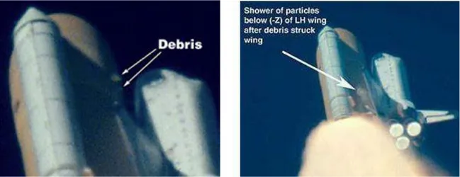
For a long time being, impact issue on composite structures was underestimated even in space industry. A catastrophic event highlighted the issue: the 1st February 2003 Columbia Space Shuttle disaster. During the STS 107 mission take-off, 16 days before the accident, a piece of foam shed from the structure connecting the external tank to the orbiter (bipod ramp), and stroke against Columbia’s left wing (Figure 2.6), creating a 150 to 250 mm diameter hole. This event was underestimated and, when the shuttle entered back into the atmosphere, high temperature plasma bled into the main structure, causing its explosion.
Figure 2.5: Laboratory reconstruction of foam impact on Columbia Space Shuttle left wing
Figure 2.6: Columbia Space Shuttle launch video screenshots at impact moment
This was not the first time a piece of foam detached. It had happened in 4 previous shuttle missions (STS-7 in 1983, STS-32 in 1990, STS-50 in 1992 and STS-112 just two launches before STS-107) but always without consequences. Therefore, it was considered just a
- 22 -
collateral effect and named as ‘foam shedding’. Here, like for airplane industry, improvements come from accidents (‘learning by accidents’ concept).
2.3 Impact causes
Impact damages on an aircraft have many causes. Three categories, based on when they could happen, can be defined: production/maintenance, boarding operation, flight. The first group includes damages as dents and delaminations caused by tools drops or saw cuts, for structure modification. But also walk on no-step areas, which are usually the most critical and sensible areas (Figure 2.7).
Figure 2.7: Detail of no-walk area on airplane wing (out of black stripes)
During boarding operation, many different events can produce an impact damage: aircraft structure can be hit by cargo or service cars (Figure 2.8), passengers or employee could hit doors surroundings with luggage during loading operations.
Figure 2.8: Detail of an impact damage on airplane fuselage caused by a service car
During flights, from take off until landing, there are multiple possible causes of damages: runway debris can strike against lower structures and wing panel, as well as against flap or movable control surfaces; hail or ice, separating from engines or wings, can hit airplane creating quite big damages; bird strike, can result in wide damages, that structure must bear safely until landing.
- 23 -
There are moreover other kinds of impact that have to be taken into account depending on what kind of airplane is designed: e.g. bullet impacts for military aircraft.
Therefore, many parameters have to be taken into account designing a composite aerospace structure:
- Damage resistance: materials and structures should be able to absorb as much impact energy as possible, resulting in a small damage, if structure does not have a peculiar crashworthiness function.
- Damage tolerance: residual strength has to be higher than a threshold, even in presence of damage.
- Inspectability: this is a real issue with composite because internal delaminations are difficult to be detected during maintenance inspections, compared with dents on metallic surfaces. Different methods have been.
- Reparability.
2.4 Impact damages
Impact on composites has different consequences compared to impact on metals. For metals, impact damages are easily detectable on structure surface and they depends on energy: if it is low, there would be an elastic behaviour that does not influence material characteristics; at higher energies, plastic deformation occurs. In this case, damage would be seen and repaired.
For composite [2.12, 2.16], on the other hand, impact damages depend on many factors: thickness, stacking sequence, matrix and fibre kinds, impact energy and velocity, etc. Moreover, due to composites fragile behaviour, failure mechanisms is not related to plastic deformation but on elastic deformation and fragile failures. This means that there could be different kind of damages in an impacted composite structure [2.3-2.4]:
- Matrix cracks: it is the most common defect and the first one to happen. Matrix cracks can propagate through different layers or in the same fibre direction. They are clearly evident after an impact transversal to load direction. Principal effect is composite rigidity reduction.
- Delaminations: it is separation between two plies. Small delaminations could reduce laminate compressive resistance of about 50%, due to fibre stability reduction under load application. They are mostly common around rivets holes or cut-outs.
- Fibre cracking: could be caused by impact in transversal to load direction or compression loads that can create local instability conditions. This damage is the
- 24 -
most dangerous for tensile loaded structures, and it is even worse because fibre failure is difficult to detect.
- Detachment at fibre/matrix interface: it could happen if at fibre/matrix interface stresses exceed locally limit loads. It could be microscopic and difficult to detect. A way to avoid this problem is a fibres surface treatment. It does not represent a dangerous damage but it could result in an easier way for water to enter inside a laminate, decreasing compressive resistance.
Impacts can be divided, according to impact velocity, in: iper-velocity (more than 2km/s), high-velocity (from 50 m/s up to 1000 m/s), intermediate-velocity (from 10 m/s to 50 m/s) and low-velocity (up to 10 m/s) impacts [2.3].
An impact produces pressure waves in the laminate: comparing time necessary to waves to go through laminate and contact time between impactator and laminate, it is possible to catalogue impact into the previously described kinds. For example, in low-velocity impacts, pressure waves can go through laminate many times before contact ends. This influences also damages: with high-velocity impacts there could be perforation and micro-delamination around event location, while with low-velocity ones result in barely visible damages on surface but with wide inner delamination.
Figure 2.9: Material response under different velocity impacts [2.17]
2.5 Low-velocity impacts
Low-velocity impacts [2.6-2.9] are dangerous events on a composite structure. They could happen due to tool drops during maintenance, luggage hitting cut-outs, etc. This kind of impact can result in quite wide inner or on back surface damages but with no evidence on the external impacted surface.
This lack of evidence could lead to an unexpected sudden failure. It has been already shown (Fig. 1.8, Chapter 1) that, due to an impact, bearing load structure capacity could suddenly go under ultimate load and, therefore, result in an unexpected damage growth and then failure.
- 25 -
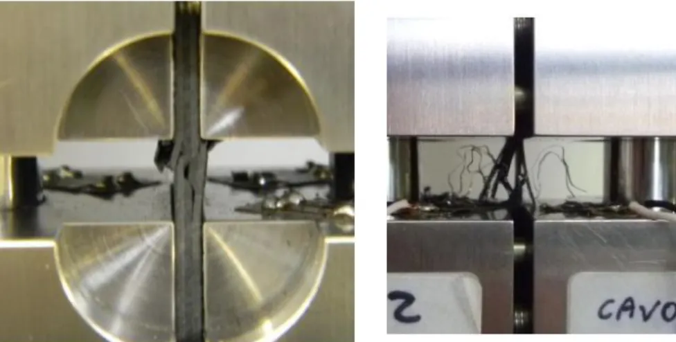
Low-velocity impacts could be compared with quasi-static events because the load-deformation behaviour is the same. This means that time of contact between impactator and structure is sufficiently long to assure entire structure reaction, and, therefore, an elastic energy absorption. This happens up to a threshold energy value, over which matrix or interface separation happen. Threshold and damage kind depend on many factors, first of all laminate thickness: thick laminate presents transversal cracks close to impact location; on the contrary thin laminate usually react as a membrane and, therefore, damages could be found on back surface, where flexural loads are the highest. These are called ‘pine tree’ and ‘reversed pine tree’ shapes (Figure 2.10) [2.3].
Figure 2.10: (a) pine tree and (b) reversed pine tree impact damage shapes [2.3]
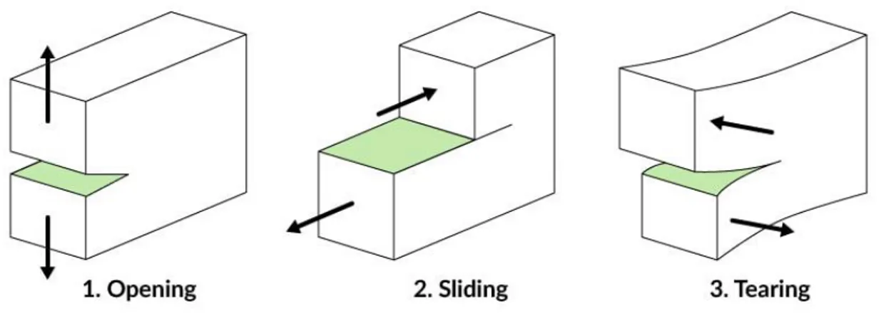
One consequence of these transversal cracks are delaminations: depending on impact force and contact surface, they occur only over a certain threshold and when there is a previous matrix crack. Delaminations can propagate in different modes: mode I or ‘opening’, mode II or ‘by shear’, mode III or ‘by tear’.
Figure 2.11: Material failure modes
Usually, mode I is related to delamination nucleation, while mode II or mixed mode to its growth.
- 26 -
Another evolution of transverse cracks is failure under contact location: by naked eyes, the only evidence of the impact is an imprint. This indentation could have different depth (creating different amount of damage), related to the involved energy and, therefore, the damage can be more or less visible.
Similarly, impactor material and dimensions can influence damage size: for a wide contact area, higher energy is needed to penetrate laminate, while for smaller areas the penetration is easier, with resulting smaller delaminations [2.13-2.15].
It is also worth to notice that stacking sequence influences delamination nucleation and growth: in fact, delamination happens commonly between layers with different fibre orientation. Therefore, an UD laminate is less prone to interlaminar interface separation.
References
[2.1] ASTM Symposium, Foreign Object Impact Damage to Composites, 1975 [2.2] FAST #48 Airbus, 2011
[2.3] S.Abrate, ‘Impact on composites structures’, Cambridge University Press, 2005 [2.4] Joshua M. Duell, ‘Impact Testing of Advanced Composites’
[2.5] M. Siliotto, ‘Valutazione analitica delle aree di delaminazione in materiali composite avanzati soggetti ad impatti a bassa velocità’, tesi di laurea magistrale, Università di Bologna, Scuola di ingegneria e architettura, Corso di laurea in ingegneria aerospaziale, a.a. 2012- riguardare la vera reference
[2.6] M.O.W. Richardson, M.J. Whisheart, ‘Review of low-velocity impact properties of composite materials’, Composites Part A, pp. 1123-1131, 1996
[2.7] A. Malhorta, F.J. Guild, ‘Impact damage to composite laminates: effect of impact location’, Applied Composite Material, 2014
[2.8] A. Malhorta, F.J. Guild, M.J. Pavier, ‘Edge impact composite laminates: experiments and simulations’, J Mater Sci, pp. 6661-6667, 2008
[2.9] M. Quaresimin, M. Ricotta, ‘Assorbimento energetico durante impatto in laminati in materiale composito’, Associazione Italiana per l’analisi delle sollecitazioni, XXXIV National congress, 2005
[2.10] Ad Vlot, ‘Low-velocity impact loading on fibre reinforced aluminium laminates (ARALL and GLARE) and other aircraft sheet materials’, TU Delft repository, 1993
- 27 -
[2.12] MIL-HDBK-17 – ‘Composite Materials Handbook’, 2002
[2.13] Mitrevski T., Marshall I.H., Thomson R., Jones R., ‘Low-velocity impacts on preloaded GFRP specimens with various impactor shapes’, Composite Structures 2006 [2.14] Woodward R. L., Egglestone G. T., Baxter B. J., Challis K., ‘Resistance to penetration and compression of fibre-reinforced composite materials’, Composites Engineering 1994 [2.15] A. Katunin, M. Zuba, ‘Influence of the impactor geometry on the damage character in composite structures’
[2.16] W.J. Cantwell, J. Morton, ‘The impact resistance of composite materials---a review’, 1991
[2.17] R. Olsson, ‘Mass criterion for wave controlled impact response of composite plates’, Composites Part A: Applied Science and Manufacturing, 2000
- 29 -
3
Experimental Impact tests
Different impact tests can be performed to study many kinds of damages. After a brief introduction to all of them, the ‘modified Charpy pendulum’ available in the MasterLab workshop, together with a description of its setup and usage, is shown.
3.1 Impact tests
There are many different ways to perform impact tests on composite materials, in order to study their behaviour. Each one has a specific velocity range of application, with different settings and issues:
- Quasi-static loading [3.1]: really slow indentation tests that can be performed by means of a hydraulic testing machine;
- Low-velocity impact [3.2]: velocity under 10 m/s, by drop weight testing (different weights, different heights to obtain different impact energies); it will deepened in the following section.
- High-velocity impact: with velocity up to 100 m/s, can be performed with gas guns (Figure 3.1); impact are fast and, therefore, damaged area is smaller. This means that geometrical considerations do not have any meaning in this contest.
This system work by means of compressed gas that pushes against sabot; its pin is released and this entire part is pushed inside a tube. When sabot reaches the end of the tube, it is stopped properly while pellet is launched out of it; it hits specimen with a constant velocity. Pellet are usually made by hardened steel or zirconium; specimen deformation can be measured by means of specific strain-gauges. - Ballistic impact: velocity up to 500m/s, made with powder guns;
- Hypervelocity impact: really high velocities obtained by means of electromagnetic guns [3.3].
- 30 -
Figure 3.1: Gas gun impact system
Many variables are implied in an impact and can change its result on the structure [3.4-3.8]:
- Indenter shape: a sharper indenter results in an easier indentation but in smaller internal damage;
- Indenter mass; - Impactor velocity;
- Impactor/clamps materials: usually indenter are in steel to better comparison, but there could still be influence due to this variable, as well;
- Target material and dimensions;
- Impact direction: relative impact direction (perpendicular, parallel or oblique to target medium plane) influences the internal damage;
- Impact location: near-edge impact can result in a wider damage due to lower materials local stiffness;
- Boundary conditions: a clamped specimen shows a wider damage compared to a simply supported one due to the lack of membrane behaviour.
In literature, many papers describing experimental campaigns on composite impact behaviour were found; most of them were related on central impacts (as described in [3.2]). Unfortunately, impacts rarely occur in such a situation, since they are more probable near cut-outs and corners as shown in 2.1 paragraph. Hence, it was worth of interest to deepen the knowledge of location influence.
Impacts are catalogued in two groups (Figure 3.2): normal and on-edge impacts. In the first, impact direction is orthogonal to material middle plane while, in the second, impacts take place on structure edges. Normal impacts could take place centrally (Central Impact, CI) or near specimen edge (Near-Edge impact, NE), while on-edges could be directed along specimen plane (In-line) or create a sharp angle with it (Oblique impact).
- 31 -
Figure 3.2: Impact locations
Throughout literature research, few papers related to normal and transversal impacts were found [3.8-3.9]. In these works, an experimental campaign on glass/epoxy laminates, impacted with different energies, was described. The impacts are located near specimen edges or directly on its edge. Using glass/epoxy it is possible to see, by naked eyes, damages created through the thickness and correlate these to compression after impact test results. It was demonstrated that composites are quite sensitive to impacts and that location is a fundamental parameter.
No studies were found related to impact location influence on impact resistance of a carbon/epoxy laminate. Hence, it was decided to deepen this material behaviour under impact loads, starting with normal impacts.
3.2 Low Velocity Impact tests
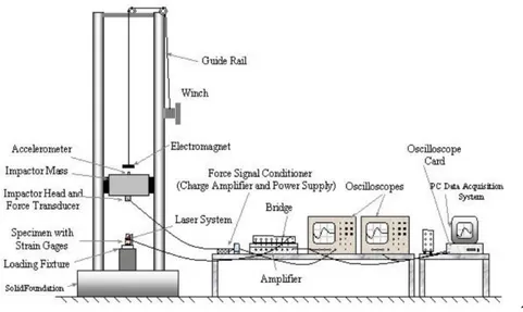
As previously said, many different methods exist for impact performance. Choosing one of them is related to which kind of velocity is under investigation. In the case of this PhD research, it was chosen to perform low-velocity impact tests, in order to obtain BVID (Barely Visible Impact Damages). The most common equipment used for this aim is a Drop weight tower (Figure 3.3) [3.2].
- 32 -
2
Figure 3.3: Drop Tower Impact test system
It consists of a weight fixed under a cart, free to glide on two or more vertical tracks. It can be fixed in a specific height and then release to obtain a certain energy impact. Specimen is fixed in a proper fixture, circular or rectangular, positioned between rails.
Figure 3.4: Drop tower fixture for specimens [3.2]
After impact takes place, weight bounce could be stop or let it go to obtain a multiple impacts tests.
After a literature and technological review of impact test procedures and facilities, it was found out that Charpy pendulum is usually used to perform impacts, as well.
Originally, it was developed for testing materials impact resistance [3.5], with a maul hitting in the middle and breaking long specimens (Figure 3.5). It is, therefore, possible to calculate absorbed and residual energy just looking at final maul position after breaking the specimen. Hence, this kind of test is a destructive test where only property of impact energy absorption is acquired.
- 33 -
Figure 3.5: Charpy pendulum tests system
In this way, it is impossible to use Charpy pendulum to obtain BVID and be able to test specimens in compression after impact. This is also the main reason of whom refer to Charpy (or Izod) pendulum as not suitable for aeronautical impact test performance: it is not representative of real impact condition on airplanes, due to different boundary conditions. [3.11-3.12].
Therefore, it was necessary to modify pendulum original set up in order to achieve the main goal. Kind of test under investigations and possible boundary conditions were taken into account to create a modified Charpy pendulum. It was design and built up in the MasterLab facilities of University of Bologna, in Forlì.
3.2.1 Charpy pendulum
The realized pendulum has been obtained modifying a structure already present: it is an L shaped 1 m tall structure with a steel bar hinged in the middle with a bearing that let bar revolve around it (with low friction). At the end of the bar, there is a cylindrical impactator with a hemispherical end. Bar is hinged in the middle to avoid any contribution of it to impact energy. In this way, impact energy is only based on impactator weight and beginning height from where weight is released.
Two versions of this pendulum were realised.
- First one, used in the first experimental campaign (described in chapter 4), had a 630 mm long steel bar hinged with a one-line bearing. On the other bar end, the impactator was attached: it was a steel cylinder with a hemispherical 7 mm diameter end, and its weight was 1.81 kg. Bar was tighten to a counterweight (Figure 3.6) in order to balance bar weight. In this way impact energy is only based on impactator weight and beginning height from where weight is released.
- 34 -
Figure 3.6: Counterweight
- Second version, differs from first only for steel bar that was in this case 1226 mm long and hinged in the middle (Figure 3.7). In this way it was already balanced, without need for the counterweight. Bearing in this case was a double line in order to have a more stable movement of the bar in the transversal direction.
Figure 3.7: Modified Charpy pendulum (second version)
Energies were calculated measuring bar angles by means of a goniometer located at the hinge. It is, in fact, possible to correlate energy level to bar angle due to trigonometric laws:
- 35 -
(3.1) 𝐸 = 𝑚𝑔ℎ
where 𝐸 is the energy, 𝑚 is the impactator mass, 𝑔 gravitational acceleration and ℎ height at which impactator should be released to obtain that energy (Figure 3.8). Therefore, the unknown, in this case, is ℎ. To calculate ℎ it is possible to use trigonometry: knowing the distance,𝑙, of the impactator centre of gravity from hinge centre, it is possible to calculate:
(3.2) 𝐴𝐵̅̅̅̅ = 𝑙 cos 𝛼
where 𝛼 is the angle that bar forms with its initial position. It is hence easy to see that ℎ is equal to:
(3.3) ℎ = 𝑙 − 𝑙 cos 𝛼 and therefore, substituting in (3.1)
(3.4) 𝐸 = 𝑚𝑔(𝑙 − 𝑙 cos 𝛼)
Equation (3.4) can be used for calculating all energies involved, it would be necessary only to change the angle involved: for actual energy, initial angle is required; for residual energy, bounce angle is used:
(3.5) 𝐸𝑖𝑛𝑖𝑡𝑖𝑎𝑙 = 𝑚𝑔(𝑙 − 𝑙 cos 𝛼𝑖𝑛𝑖𝑡𝑖𝑎𝑙) (3.6) 𝐸𝑟𝑒𝑠𝑖𝑑𝑢𝑎𝑙 = 𝑚𝑔(𝑙 − 𝑙 cos 𝛼𝑏𝑜𝑢𝑛𝑐𝑒)
Calculation of absorbed energy could be done after knowing both initial and residual energies, by means of:
(3.7) 𝐸𝑎𝑏𝑠𝑜𝑟𝑏𝑒𝑑 = 𝐸𝑖𝑛𝑖𝑡𝑖𝑎𝑙− 𝐸𝑟𝑒𝑠𝑖𝑑𝑢𝑎𝑙
where 𝐸𝑎𝑏𝑠𝑜𝑟𝑏𝑒𝑑 is the energy absorbed by specimen due to elastic response and damage formation, 𝐸𝑖𝑛𝑖𝑡𝑖𝑎𝑙 is given by (3.5), 𝐸𝑟𝑒𝑠𝑖𝑑𝑢𝑎𝑙 is given by (3.6).
3.2.2 How to use ‘modified pendulum’ at Unibo (MasterLab) laboratories
This modified pendulum is easy to use:
- adjustable feet are under main plate (Figure 3.8-3.9) to level the pedestal inclination;
- 36 -
Figure 3.8: level used to avoid longitudinal ground inclination
Figure 3.9: level used to avoid transversal ground inclination
- specimen is put in the fixture (Figure 3.10), where it is fixed in position during test by means of six screws;
- pendulum structure is moved transversally till impactator is in the right position to obtain impact on previously decided location on specimen; it is then fixed with 4 screws to steel pedestal (Figure 3.11);
- 37 -
Figure 3.11: screws to connect pendulum to the basement
- bar pivot is moved back or forward and then fixed in position to have bar orthogonal to the floor. It results, therefore, an impact normal to specimen middle plane (Figure 3.12);
Figure 3.12: Level used to check bar impact position
- goniometer is set and fixed and test can start.
3.2.3 Accelerometer acquisitions
In the first version of this pendulum (where the only difference was bar shape and balancing method), an accelerometer had been located at rear impactator surface (Figure 3.13). Multiple impact tests were performed on a carbon/epoxy laminate.
This was made to obtain information regarding pendulum dynamics.
The accelerometer was a PCB Mod 356B21. It has nominal sensitivity of 10 mV/g on acquisition channels with a frequency range of 2-7000 Hz; full scale of 10 V equal to 500g. Acquiring system is LSM SCADASCM 05; sampling frequency used was 6400 Hz.
- 38 -
Figure 3.13: Accelorometer at the impactor end
Data acquired are shown in following pictures (Figure 3.14-3.18); in those tests acquisition time was set as 5 sec and data from main impact and 5/6 rebounds were recorded. For the work presented in this thesis, only the first impact is however taken into account.
Figure 3.14: Acceleration through the thickness direction
- 39 -
Figure 3.16: Acceleration acquired during 5 J impact test (max value 74.66 g)
Figure 3.17: Acceleration acquired during 6 J impact test (max value 81.54 g)
Figure 3.18: Acceleration acquired during 7 J impact test (max value 83.35 g)
- 40 -
Figure 3.19: Max acceleration values
The x-direction acceleration grows with impact energy reaching an asymptote from 7 J energy impact on.
The modifications in pendulum structure do not influence x-direction dynamics; therefore, values of acceleration are supposed to be the same.
For every energy level, almost the same acceleration peak value is achieved in all performed tests; therefore, this shows the reliability and repeatability of impact tests with this ‘modified pendulum’.
References
[3.1] ASTM D6264/D6264M – 12, Standard Test Method for Measuring the Damage Resistance of a Fiber-Reinforced Polymer-Matrix Composite to a Concentrated Quasi-Static Indentation Force.
[3.2] ASTM D7136/D7136M – 15, Standard Test Method for Measuring the Damage Resistance of a Fiber-Reinforced Polymer Matrix Composite to a Drop-Weight Impact Event.
[3.3] S. Abrate, Impact on Composite Structures, Cambridge University Press, New York, 1998.
[3.4] M. Sadighi, et al., Impact resistance of fiber-metal laminates: A review, International Journal of Impact Engineering, 2012.
0 10 20 30 40 50 60 70 80 90 3 4 5 6 7 8 Ac ce le ratio n [ g] Impact energy [J]
Accelerometer acquisition
- 41 -
[3.5] S. Agrawal, et al., Impact damage on fibre-reinforced polymer matrix composite - A review, Journal of Composite Materials, 2013.
[3.6] W. J. Cantwell et al., The Impact Resistance of Composite Materials-A Review, Composites, 1991.
[3.7] G.B. Chai, et al., Low velocity impact response of fibre-metal laminates – A review, Composite Structures, 2014.
[3.8] A. Malhotra, F.J. Guild, ‘Impact damage to composite laminates: effect of impact location’, Applied Composite Material, 2014.
[3.9] Malhotra, A., Guild, F.J. & Pavier, Edge impact to composite laminates: experiments and simulations, M.J. J Mater Sci (2008).
[3.10] ASTM D6110-10 Standard Test Method for Determining the Charpy Impact Resistance of Notched Specimens of Plastics
[3.11] W. Hufenbach et al., Charpy impact test on composite structures – An experimental and numerical investigation, Composites Science and Technology, 2008.
[3.12] A. C. N. Singleton, On the mechanical properties, deformation and fracture of a natural fibre/recycled polymer composite, Composites: Part B, 2003.
- 43 -
4
Compression After Impact (CAI) tests
In this chapter, a brief description of all compression and CAI test fixtures on composites is given. In particular, CLC line guides are described.
4.1 Compression tests on composite materials
Compressive resistance of composite materials is not as high as tensile resistance due to their intrinsic nature. In fact, compression loads act on matrix properties and matrix/fibre adhesion. Therefore, testing this characteristic of composites is an important experimental field.
This is even more important when related to impacted materials: due to inner damages, close plies adhesion could be compromised and a not uniform load distribution could take place (Figure 4.1).
- 44 -
Many different kind of fixture have been developed to be used with advanced reinforced plastics. These can be divided into 3 main groups: Shear loaded, Sandwich-beam compression, End loaded. In the following section, fixtures are described together with their advantages and disadvantages.
4.1.1 Shear loaded
There are two main fixtures: - Celanese [4.1-4.4] (Figure 4.2)
Developed in 1971 by I.K.Park of Celanese Corporation, it transfers shear load by means of conical grip surfaces. Main issue is related to a not perfectly uniform load transfer, a common problem for this kind of compression tests.
Moreover, there could be possibility of bending that could give rise to flectional instability, due to peculiar surfaces structure. Geometrical tolerances, of both specimens and fixture, are strict (±0,002’’), due to need to have a proper coupling at grip surfaces.
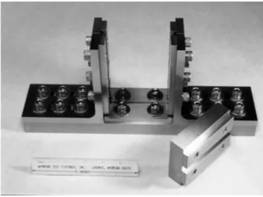
- IITRI (‘B method ’ASTM D 3410, 1987’) [4.1-4.4] (Figure 4.3-4.4)
Developed in 1977 by Hofer and Rao at Illinois Institute of Technology Research Institute (IITRI), trying to solve issues related to Celanese. It is made of flat wedges which can solve load alignment and specimen buckling. It is characterised of a high
- 45 -
results reliability and, therefore, data acquired by mean of this fixture are usually used as a term of comparison. Main drawback is its weight: it is a massive structure of about 40 kg with a moving part of 16 kg; moreover, costs are high due to geometrical tolerances for cavities which house wedges.
Figure 4.3: IITRI test fixture scheme
Figure 4.4: IITRI test Fixture [4.3]
4.1.2 Sandwich-Beam Compression Test Method
This kind of test is described in ASTM D 5467-93 [4.5], even if it was already addressed as ‘method C’ in ASTM D 3410 [4.1]. It consists of a four points bending test on sandwich-beam specimens (two layers of composite pre-preg with a honeycomb core in the middle). Hence, the upper surface is in compression. Load is supposed to be uniform
- 46 -
due to low thickness of the tested surface in comparison with specimen thickness (Figure 4.5-4.6).
Figure 4.5: Sandwich-beam Compression test method scheme [4.5]
Figure 4.6: Sandwich-beam Compression test fixture [4.3]
This method gives high compressive resistance that it is not representative of real material behaviour; this is caused by honeycomb stabilising composite compression buckling. At the same time, however, results could be influenced by honeycomb failure or interface separation. Therefore, specimens preparation needs time, skills and it costs a lot, due to many factors that should be checked to respect requirements, and to avoid effects on tests result.
4.1.3 End-loaded Test Method
There are two methods in this category:
- Modified ASTM D695 [4.1][4.3-4.6] (Figure 4.7)
Derived from ASTM D695, fixture for un-reinforced plastics. Specimens are rectangular and not dog-bone shaped as in the original version. Load is transferred
![Figure 4.2: Celanese test fixture [4.3]](https://thumb-eu.123doks.com/thumbv2/123dokorg/8129852.125793/54.892.171.732.571.947/figure-celanese-test-fixture.webp)
![Figure 4.5: Sandwich-beam Compression test method scheme [4.5]](https://thumb-eu.123doks.com/thumbv2/123dokorg/8129852.125793/56.892.231.645.171.429/figure-sandwich-beam-compression-test-method-scheme.webp)