DOI: 10.1002/ctpp.201900076
O R I G I N A L A R T I C L E
Protons and carbon ions acceleration
in the target-normal-sheath-acceleration regime using
low-contrast fs laser and metal-graphene targets
Lorenzo Torrisi
1Mariapompea Cutroneo
2Alfio Torrisi
21Dipartimento di Scienze Matematiche, Informatiche, Scienze Fisiche e Scienze della Terra (MIFT), Università di Messina, Messina, Italy
2Nuclear Physics Institute of ASCR, Husinec- ˇRež, Czech Republic
Correspondence
Lorenzo Torrisi, Dipartimento di Scienze Matematiche, Informatiche, Scienze Fisiche e Scienze della Terra (MIFT), Università di Messina, V.le F.S. d'Alcontres, 31, 98166 S. Agata, Messina, Italy.
Email: [email protected]
Funding information
CANAM, LM 2015056 P108/12/G108; Università degliStudi di Messina, Research & Mobility
Abstract
fs pulsed lasers at an intensity of the order of 1018W/cm2, with a contrast of 10−5,
were employed to irradiate thin foils to study the target-normal-sheath-acceleration (TNSA) regime. The forward ion acceleration was investigated using 1/11 μm thick-ness foils composed of a metallic sheet on which a thin reduced graphene oxide film with 10 nm thickness was deposited by single or both faces. The forward-accelerated ions were detected using SiC semiconductors connected in time-of-flight config-uration. The use of intense and long pre-pulse generating the low contrast does not permit to accelerate protons above 1 MeV because it produces a pre-plasma destroying the foil, and the successive main laser pulse interacts with the expanding plasma and not with the overdense solid surface. Experimental results demon-strated that the maximum proton energies of about 700 keV and of 4.2 MeV carbon ions and higher were obtained under the condition of the optimal acceleration procedure. The measurements of ion energy and charge states confirm that the acceleration per charge state is measurable from the proton energy, confirming the Coulomb–Boltzmann-shifted theoretical model. However, heavy ions cannot be accelerated due to their mass and low velocity, which does not permit them to be sub-jected to the fast and high developed electric field driving the light-ion acceleration. The ion acceleration can be optimized based on the laser focal positioning and on the foil thickness, composition, and structure, as it will be presented and discussed.
K E Y W O R D S
ion acceleration in plasma, laser-generated plasma, SiC detector, TNSA
1
I N T R O D U C T I O N
The ion acceleration of protons and carbon ions is of special interest to be employed in different fields, such as in microelectronics, chemistry, nuclear physics, and radiotherapy.[1–3]
Literature reports that the target-normal-sheath-acceleration (TNSA) ion acceleration using fs lasers confers kinetic energy to protons higher than 1–10 MeV employing the proper laser parameters and irradiation conditions and using adapt target composition and geometry.[4,5]
Kaluza et al.[6]have demonstrated that a proton acceleration of 3 MeV can be obtained using 150 fs pulses at 1019W/cm2
intensity irradiating an Al foil with an optimal thickness of 2 μm and an amplified spontaneous emission (ASE) at a pre-pulse
Contrib. Plasma Phys. 2019;e201900076. www.cpp-journal.org © 2019 WILEY-VCH Verlag GmbH & Co. KGaA, Weinheim 1 of 12 https://doi.org/10.1002/ctpp.201900076
duration of 0.5 ns. It was also demonstrated by Ceccotti et al.[7] that 5 MeV protons can be obtained using 65 fs pulses at
5 × 10¹⁸W/cm2, with a contrast of 10−6and p-polarization, irradiating a mylar foil with an optimal thickness of 100 nm. Torrisi
et al.[8] have recently demonstrated that it is possible to accelerate protons to 3 MeV energy by using fs laser at high contrast
and advanced targets based on reduced grapheme oxide foils covered with Au films.
Moreover, the possibility to accelerate protons above 10 MeV using 2 × 10¹⁸W/cm2intensity, 500 fs pulse duration, and
ultra-high-contrast pulses with a contrast level higher than 10−10was demonstrated by Khaghani et al.,[9]irradiating structured
Cu micro-pillar arrays standing on a micrometric Ag planar film.
The obtained high proton acceleration was recorded under particular experimental conditions of the laser focal position and of the focal spot diameter, using p-polarized laser pulse at a suitable incidence angle, in order to induce longitudinal plasma waves, perfect planar surface, and high adhesion of the target to a suitable holder, avoiding target deformation during the laser ablation. In addition, in order to use high electron plasma density, advanced targets based on high electrical and thermal conduc-tivity and special resonant absorbent nanostructures have been used, such as those based on thin gold foils, nanoparticles, and nanorods.[10]
In all cited literature, the high proton acceleration is obtained using a high contrast of the laser pulse, that is using the main peak anticipated by a very low pre-pulse (low in energy and duration). The use of high contrast level permits to induce high laser intensity interaction with solid matter, transferring of high photon energy to electrons at the solid density and generation of high electric fields driving the forward ion acceleration in the rear side of the target. The use of low contrast level, instead, means to use a high-energy pre-pulse able to destroy the solid target generating a pre-plasma and the interaction of the main laser pulse with this pre-plasma, which can be characterized by high or low electron density. This pre-plasma may develop a different interaction of the transmitted laser to the overcritical target density. The electric field driving the forward ion acceleration decreases when the laser contrast is very low and the pre-pulse is so intense to induce target vapourization. Sometimes, the electric field-accelerating ions may increase if the pre-plasma is not so dense, laser can be self-focused at the wavelength size in the high refraction index of the pre-plasma and the main laser pulse intensity of the solid target increases.[11]
The use of high laser intensity having high contrast, of nano-structured foils with a composition enhancing the laser absorp-tion, of the p-polarized laser promoting plasma wave resonant absorpabsorp-tion, and the choice of the optimal conditions of the laser focusing and target thickness permit to enhance the electron density transmitted to the rear side of the thin foils.[12]Under
such conditions, the forward ion acceleration produced in the TNSA regime is promoted by a quasi-static high electric field E, developed in the rear side of the target having a duration comparable with the laser pulse (tens of fs), driving the forward ion acceleration shown by the relation[13,14]:
𝐸 =
√
𝑘𝐵𝑇 𝑛𝑒
𝜀0 ,
(1)
where kBis the Boltzmann constant, T is the plasma temperature, neis the electron density, and𝜀0is the vacuum permittivity.
The optimal conditions are chosen in order to maximize the electric field of the ion acceleration.
The use of high energetic and prolonged pre-pulse (low contrast conditions) can be responsible for a dense pre-plasma generation and of an interaction of the main laser pulse with a low-density plasma, decreasing the electron density and producing a lower electric field driving the ion acceleration, as will be demonstrated in this article.
In addition, in the presence of a not reproducible laser pulse, it is possible that a double main pulse, separated by ps times, can be generated. The presence of double main laser pulse at low contrast irradiating a thin structured foil may induce two stage acceleration processes, producing plasma in which self-focusing and shockwave effects can lead to much higher conversion efficiency and increase of the accelerated proton energy, as occurred during the experiments reported by Markey et al.[15]
In order to enhance the ion acceleration, advanced targets based on heavy metals were employed to increase the electron den-sity, ne, of the produced non-equilibrium plasma. Their surface was covered with a thin film of reduced graphene oxide (rGO),
10 nm in thickness, a material showing high electrical and thermal conductivity, low reflectivity, low density, high transmis-sion to the used laser wavelength (800 nm), and high mechanical resistance.[16]Its use, as a front surface coating illuminated
by the laser, may enhance the laser-plasma energy conversion due to the high absorption and low reflectivity of the target to the incident laser light, which is totally transmitted in the IR region to the below metallic substrate. The rGO film, in fact, has a black surface reducing significantly the reflection coefficient in the visible and near IR regions. Thus, it enhances the laser energy absorbed and transmitted to the metallic substrate. Moreover, the material has a good electrical conductivity and low density, and favours the laser production of surface relativistic electrons, which may cross the carbon-structured target with low scattering. The hot electron density produced in the back of the irradiated foil enhances increasing the electric field driving the ion acceleration.
SiC 5; -26° IC 1; 28° Target SiC 8; 0° Laser SiC 7; 28° SiC 6; 26° 1050 1100 1150 1200 1250 1300 0 200 400 600 800 Cm = 0.71% Am = 0.74% SiC AZ 80 @ -200 V 20 Coarse Gain Shaping Time 10 s Detector Source = 1.5 cm Pu = 0.80% 4,8 5,0 5,2 5,4 5,6 5,8 6,0
Energy (MeV) bias
oscilloscope 1050 1100 1150 1200 1250 1300 0 200 400 600 800 Cm = 0.71% Am = 0.74% SiC AZ 80 @ -200 V 20 Coarse Gain Shaping Time 10 s Detector Source = 1.5 cm Counts Channel Pu = 0.80% Energy (MeV) 4.8 5.0 5.2 5.4 5.6 5.8 6.0
(a)
(b)
(c)
(d)
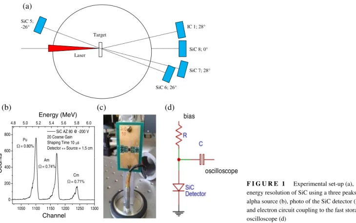
F I G U R E 1 Experimental set-up (a), energy resolution of SiC using a three peaks alpha source (b), photo of the SiC detector (c), and electron circuit coupling to the fast storage oscilloscope (d)
The use of the rGO surface layer makes the target more absorbing and better transmitting the pulse to the metallic substrate. The surface of the irradiated target appears more uniform and less rough using the rGO layer and it is expected an increment of the number of relativistic coherent electrons accelerated at the target surface.
The rGO superficial film, used as a coating of the metallic substrate foil, permits the acceleration not only of protons but also of light carbon ions. The rGO structure, which becomes reduced and conductive under the first pre-pulse irradiation,[17]
represents a low-density and thin conductive carbon film capable of enhancing the ion acceleration at low laser contrast. In previous measurements, in fact, the same laser system was employed to accelerate protons from carbon targets at a maximum kinetic energy of only 250 keV.[18]In this article, we want to demonstrate that the simple trick of using rGO thin coverage films
may enhance significantly the proton acceleration permitting also the forward acceleration of carbon ions.
To investigate the maximum kinetic proton energy obtainable maintaining the laser contrast low, that is using an ASE contrast of only 10−5 producing an intense pre-pulse and pre-plasma, it was important to optimize the laser parameters, the
irradiation conditions, and the target properties and thickness. We will demonstrate that under conditions of 800 nm wavelength, low contrast (10−5), 125 mJ pulse energy, 39 fs pulse duration, and 6 μm rGO target, the obtainable maximum proton energy is
not of the order of 100 keV, as reported in the literature,[18]but it is of the order of 700 keV or more. In addition, we want to
demonstrate that not only protons but also carbon ions are accelerated under TNSA conditions used in the experiment, as will be presented and discussed.
2
E X P E R I M E N T A L S E T- U P
The measurements were performed with the experimental set-up reported in Figure 1a, using thin foils irradiated in the TNSA regime. SiC and ion collectors (IC) detectors were placed in the forward and backward directions, at different distances and angles, and used in the time-of-flight (TOF) configuration. By knowing the flight distance from the target to the detector and by measuring the time of arriving of the ions, it is possible to measure the faster ion velocities. To this, both a fast storage oscilloscope (8 GHz frequency band, sample rate 20 GS/s) with a low input impedance (50 Ω) and a fast detection electronics were employed, as already reported in the literature.[19]SiC permits to detect in the same TOF spectrum the faster X-rays, the
relativistic electrons, which interfere with the photon detection enhancing their intensity and time duration, the cold electrons at energies of the order of 10 keV and the ions, from the faster protons to the slower carbon ions at different charge state.
Figure 1b shows the high-energy resolution of the SiC detectors (0.74% at 5.5 MeV alpha particles), which is comparable to that of a traditional Si detector, measured using the three peaks alpha sources, as reported in the literature (b).[20]Moreover,
the figure reports the photo of a typical SiC detector (c) and the electron circuit coupling the acquired signal to the fast storage oscilloscope using a power supply resistor of 1 MΩ and a coupling capacitance of 100 nF (d).
The SiC detectors show important advantages with respect to Si detectors. Due to their higher energy gap (3.3 eV), SiCs are blind to the high intensity of visible light developed in plasma. Their leakage current at room temperature is of about three-order magnitude lower with respect to silicon, permitting to resolve also a minimum amount of radiation energy with a high signal-to-noise ratio. Their maximum working temperature is of about 1200◦C, four times higher with respect to the silicon and their resistance to the generation of defects is higher with respect to silicon (displacement energy 25 eV, against 15 eV in silicon).[19–21]
SiC detectors have 200 nm thickness Ni2Si Schottky contacts as surface metallization. An Al absorber was added in front of
the detector in some measurements to absorb low-energy heavy ions and to transmit only energetic protons. For example, some SiC detectors were employed with a thin Al film, 4 μm in thickness, as an absorber placed in front to them to filter different energetic particles. The 4 μm thickness corresponds to the range of 400 keV protons, thus its use permits to filters protons with energy higher than 400 keV and to stop carbon ions with kinetic energy lower than 4.5 MeV.
The experimental set-up has used a TW laser (Ti-Sapphire Eclipse laser system) delivering 39 fs pulse duration, 800 nm wavelength, high pedestal intensity (IASE), 9.5 μm focal spot diameter, 1018W/cm2main pulse intensity, and a low contrast of
about 10−5, operating in a single mode and emitting p-polarized radiation.
A curve related to the used laser pulse, showing the pedestal duration and its relative intensity, is shown in Figure 2a. The pedestal duration is about 10 ps, while the high laser pulse exhibits a duration of 39 fs. The laser is focused by f/3 off-axis parabolic metal mirror and hits p-polarized onto the target, with an incidence angle selectable between 0◦and 60◦. Measurements usually were performed at a main pulse energy EL of 130 mJ, thus the pre-pulse energy being four orders magnitude lower
corresponds to about 13 μJ. This energy reported to the pre-pulse duration and laser spot size 10 μm in diameter produces a pre-pulse intensity of about 1.7 × 10¹²W/cm2. This laser intensity is sufficient to produce the target foil disruption and a
high-density plasma formation, so as reported in the literature.[22]Thus, the main laser pulse hits this high-density pre-plasma
and not a solid target. Pre-plasma may produce an undercritical vapour, in which a high refractive index can be generated and may induce the main pulse to be self-focused on the overcritical target. This phenomenon may produce a lower spot size, of the order of the laser light wavelength, producing increasing of the laser intensity and consequent enhancement of the ion acceleration process, as reported in the literature.[23] However, the produced plasma during the 10 ps expands at supersonic
velocity in a vacuum reducing its density, thus, the successive main laser pulse may propagate in this possible undercritical plasma and enhance the energy released to the plasma particles. Under such conditions, the electron density of the accelerated relativistic electrons generally decreases together to the electric field driving the forward ion acceleration.
Figure 2b shows a photo of the experimental set-up inside the vacuum chamber with evidence of the X–Y–Z target holder positioner containing up to 105 targets. The employed targets consist in micrometric foils of gold, tantalum, and nickel with a thickness within 1 and 11 μm. A thin film of strong adherent rGO grapheme is deposited above these foils by single or both faces, with a nanometric thickness of 10 nm.
The targets were irradiated from the rGO face to reduce the laser reflection on the surface and to generate from the below metal the relativistic electrons crossing the target thickness and emerging from the rear side at which protons and carbon ions are accelerated. The particles are driven by the electric field produced by the charge separation developed in the rear side of the thin foil, as reported in the previous article.[24]The targets were prepared at Messina University, characterized for optical absorbance versus wavelength in the visible–near IR regions, for roughness and morphology using a surface profiler (Tencor P10) and a scanning electron microscope (SEM), respectively. Thickness measurements of the thin foils and of the rGO graphene films were obtained in Messina University and in CANAM lab, at Nuclear Physics Institute in Rez (Czech Republic), by using Rutherford Backscattering Spectrometry and Elastic Recoil Detection Analysis with MeVs H+and He+beams.[25]
The ion stopping powers, range, and energy loss were calculated using the SRIM simulation code.[26]
A special holder, visible in the photo of Figure 2b, was prepared at Physics Department of Messina University with cone-shaped holes with 1 mm diameter on which very adherent thin flat foils can be strongly glued. The holder geometry reduces the target deformation during the first instant of the laser incidence and maintain very flat or concave or convex the target surface. These geometries of the target modify significantly the ion acceleration and focalization, as reported in the literature.[27]
3
R E S U L T S
The obtained proton accelerations were recorded under particular experimental conditions of the laser focal position, focal spot diameter (focus was changed and was optimized it positioning using 10 μm diameter with uniform intensity), using p-polarized laser pulse incident orthogonally to the perfect planar surface, using high adhesion of the target to a suitable holder. Many
(b)
(a)
-2.0x10⁻¹¹ -1.0x10⁻¹¹ 0.0 1.0x10⁻¹¹ 10-6 10-5 10-4 10-3 10-2 10-1 100 Delay (sec) Ti Sapphire Eclipse laser system laser pulse (FWHM) = 39 fs Pedestal N o rma liz ed in te n sity Main peakF I G U R E 2 Typical laser pulse shape at low contrast used in the presented experiment (a) and photo of the vacuum chamber showing the X–Y–Z target holder positioner (b)
SiC-TOF spectra were acquired during TNSA ion acceleration using the proposed metallic substrate covered by a thin rGO carbon film.
An optimal SiC-TOF spectrum was obtained in such experiments irradiating 2 μm Ta foil covered with 10 nm graphene film in both sides (front and back), as reported in Figure 3a. The carbon in back permits to accelerate carbon ions together protons. The target was irradiated with a focal position FP = +100 μm (+ indicates a focal position inside the target surface) in order to have higher spot size and high density of electrons transmitted to the rear face of the foil. The increment of the spot, in fact, enhances the number of electrons accelerated by the laser light at the target surface. The spectrum reports the fast and very high photopeak, with a duration of about 7 ns due to the X-ray emissions from the laser-generated plasma, triggering the TOF temporal data, followed by a background of fast electrons (hot electrons) and of a slower high and large peak due to the ion detection at different velocities. The minimum TOF value of the detected electrons signal separated from the photopeak occurs at about 10 ns, corresponding to a kinetic energy of about 15.6 keV, but it does not exclude the presence of faster electrons arriving at the detector during the photopeak detection. The minimum TOF value of the detected ions occurs at about 64.5 ns. Due to the TOF flight distance of 0.745 m, it corresponds to protons at a maximum kinetic energy of 700 keV. The spectrum shape and time extension up to 350 ns indicates that protons do not represent the only detected ions. At 350 ns, the corresponding proton energy should be 23 keV. TNSA may accelerate, in fact, light ions but not heavy ones due to their high mass and low velocity, which does not permit to arrive in time to be subjected to the brief and high electric field acceleration peak during a time comparable with the laser pulse duration.
A measurement performed using a SiC detector covered with 4 μm Al foil absorber placed at 0◦ was used to acquire a spectrum of all protons, absorbing those with an energy lower than 400 keV. The Al foil absorbs also the carbon ions with an energy lower than 4.5 MeV. Thus, the expected spectrum should report only a proton peak due to the protons with an energy higher than 400 keV and the absence of carbon ions, in agreement with the lower spectrum reported for comparison in the same Figure 3a (red-coloured spectrum).
The high ion peak yield due to carbon ions indicates maximum carbon kinetic energy of about 4.3 MeV, as a result of the higher ion charge state acceleration. Assuming the 700 keV proton acceleration to be representative of the ion acceleration per charge state, it means that the maximum C charge state is 6+, as expected, should be 0.7 × 6 = 4.2 MeV and that
F I G U R E 3 Typical TOF-SiC spectrum of ion acceleration up to 700 keV in the target-normal-sheath-acceleration regime irradiating a 2 μm Ta foil (a) and Coulomb–Boltzmann-shifted ion peak deconvolution for protons and the six charge states of the carbon ions (b) 0 50 100 150 200 250 300 350 0 2 4 6 Target: C/Ta 2 m/C EL= 135mJ, = 30 fs, FP= +100 m,
inc=0°, SiC 8 @ -500V, 0° forward,
d = 74.5 Yield (mV) TOF (ns) H+=700 keV C6+ =4.3 MeV C1+ =700 keV H+ C6+ C5+ C4+ C3+ C2+ C+
Avg Plasma Temperature = 35.25 keV Avg Plasma Potential = 509.68 kV
(b)
0 50 100 150 200 250 300 350 0 1 2 3 4 5 6 C1+ =700 keV C6+=4.3 MeV H+=700 keV # 168, Target C/Ta 2 m/C EL= 135mJ, = 30 fs, FP= +100 m, inc=0°, SiC 8 @ -500V, 0° forward, d = 74.5 Yield (mV) TOF (ns)(a)
with Al filter (4 m)of C1+ at 0.7 MeV, very near to the experimental value of the maximum carbon ions and to the slower carbon peak
position.
This result is in good agreement with the literature, indicating that generally, the ion energy distribution has a Boltzmann-like shape for the different charge states, and many times, especially at lower laser intensity and using pulses of greater duration, it follows the Coulomb–Boltzmann-shifted (CBS) function, as reported in the literature.[28]The development of the high electric
field in the rear side of the thin foil accelerates not only protons but also light ions of the target composition. Such ions can have a high charge state thus they can be accelerated proportionally to their charge state, in agreement with the CBS model. For a long laser pulse duration, the compositional ion acceleration is demonstrated by many experimental data,[19,28]while for high laser intensity using fs lasers, this acceleration is detected mainly for light ions and not for heavy ones. The low velocity of heavy ions, in fact, does not permit to move quickly the ions to be subjected to the electric field developed in the rear side during the laser pulse duration. In addition, the light-accelerated ions produce a Coulomb shield to the slow ions reducing significantly their acceleration. Low proton emission, due to the hydrogen contamination, does not shield completely the other ion emission, and surface carbon ions can also be emitted and accelerated. No presence of the heavy Ta ions was detected in the TOF spectra. Figure 3b reports the CBS ion deconvolution showing the possible contribution of accelerated protons and six charge states of carbon. The obtained energies and the potential shift are consistent with the results and the average plasma temperature calculable using the CBS function is of about 35 keV.
This temperature is not so high, considering that from the TNSA regime it can be evaluated by the relativistic relation:[29–31]
𝑘𝐵𝑇 = 𝑚0𝑐2 ⎛ ⎜ ⎜ ⎝ √ 1 + 𝐼0𝜆 2 𝐿 1.37 × 10¹⁸ − 1 ⎞ ⎟ ⎟ ⎠ , (2)
0 100 200 300 0 2 4 6 8 C6+ = 870 keV tek09 #216, 128 mJ, 30fs, SiC8 @-500V, 0° forward, d=74.5 cm Target C/Au 10 m/C Yield (mV) TOF (ns) H+= 145 keV
(b)
0 100 200 300 0 2 4 6 8 10 12 14 16 Target: C/Au 5 m/C EL= 124mJ, = 30 fs, inc=0°, 0° forward; SiC8, d = 74.5cm Yield (mV) TOF(ns) H+=308 keV C6+= 1.88 MeV C1+=308 keV(a)
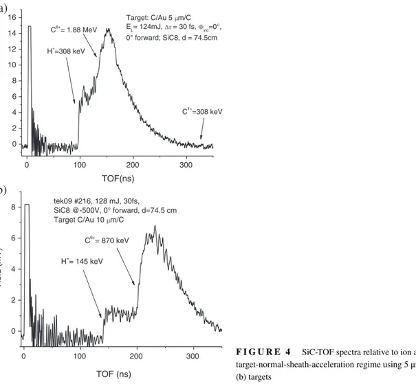
F I G U R E 4 SiC-TOF spectra relative to ion acceleration in the target-normal-sheath-acceleration regime using 5 μm Au (a) and 10 μm Au (b) targets
where m0is the rest electron mass, c the light velocity, I0the laser intensity (in W/cm2), and𝜆Lthe laser light wavelength (in
μm units). The theoretical temperature evaluation in our case is of the order of 100 keV.
Under similar conditions were irradiated thin foils of Au with different thicknesses covered with 10 nm graphene film placed on the frontal face of laser irradiation.
Figure 4 reports the SiC-TOF spectral comparison obtained detecting the forward radiation emitted by the laser irradiation of a 5 μm Au foil (a) and a 10 μm Au foil (b), both covered in surfaces with the 10 nm rGO film (front and back).
The SiC-TOF spectrum (Figure 4a) of the rGO/Au (5 μm)/rGO indicates that a maximum forward proton acceleration occurs at about 97 ns, corresponding to 308 keV for the TOF flight distance of 0.745 m, with a maximum carbon ion energy at about 135 ns, corresponding to 1.88 MeV (six times the proton energy). Thus, the maximum ion acceleration is evaluated to be of 308 keV per charge state. The spectrum reports the fast and very high photopeak, with a duration of about 8.5 ns due to the detection of X-ray emissions and relativistic electrons from the laser-generated plasma, triggering the TOF temporal data, followed by a background of fast electrons and of a slower high and large peak due to the ion detection at different velocities.
The SiC-TOF spectrum (Figure 4b) of the rGO/Au (10 μm)/rGO indicates that maximum forward proton acceleration occurs at about 141 ns, corresponding to a maximum kinetic energy of 145 keV, with a maximum carbon ion energy of about 870 keV (six times the proton energy). Thus, the maximum ion acceleration is evaluated to be 145 keV per charge state. The minimum TOF value of the detected electron signal separated from the photopeak occurs at about 11 ns, corresponding to a kinetic energy of about 12.3 keV, but it does not exclude the presence of faster electrons arriving during the photopeak duration
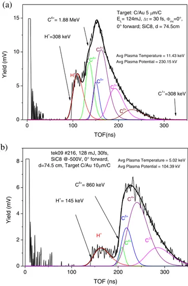
The mathematical ion deconvolutions of the spectra of Figure 4a,b are reported in Figure 5a,b, respectively. The deconvolu-tions were performed using the CBS-like function and permit to evaluate not only protons but also the other six carbon charge state contributions to the detected ions. The single ion distribution is a Boltzmann like, with a cut-off at the maximum value, and shifted towards high energy increasing the charge state. The fit permits also to evaluate the average potential of the plasma, which is 230 and 104 kV for the Au foil of 5 and 10 μm, respectively, and the equivalent average plasma temperature, which is 11.4 and 5 keV for the Au foil of 5 and 10 μm, respectively.
F I G U R E 5 Coulomb–Boltzmann-shifted deconvolutions from the SiC-TOF spectra relative to protons and carbon ions for 5 μm Au (a) and 10 μm Au (b) targets
0 100 200 300 0 5 10 15 Target: C/Au 5 m/C EL= 124mJ, = 30 fs, inc=0°, 0° forward; SiC8, d = 74.5cm Yield (mV) TOF(ns) H+ =308 keV C6+ = 1.88 MeV C1+ =308 keV
(a)
H+ C6+ C5+ C4+ C3+Avg Plasma Temperature = 11.43 keV Avg Plasma Potential = 230.15 kV
C2+ 0 100 200 300 0 2 4 6 8 C6+ = 860 keV tek09 #216, 128 mJ, 30fs, SiC8 @-500V, 0° forward, d=74.5 cm, Target C/Au 10 m/C Yield (mV) TOF (ns) H+ = 145 keV H+ C6+ C5+ C4+ C3+
Avg Plasma Temperature = 5.02 keV Avg Plasma Potential = 104.39 kV
(b)
The low electron temperature can be explained on the basis of the low laser contrast, which uses high pre-pulse energy and duration to irradiate the solid target before the arrival of the main pulse. The pre-pulse may generate a dense pre-plasma in which electrons can be accelerated. They can disturb the main laser interacting with the overcritical target and can be partially absorbed and scattered in the pre-plasma, decreasing the final electron density and temperature.
These results indicate that decreasing the Au foil thickness increases the ion acceleration because it optimized the target thickness to enhance the electrical field driving the ion acceleration. In fact, measurements performed using 2.0 μm Au foil covered by the 10 nm rGO give a result similar to that of Ta with a maximum proton acceleration of 750 keV and a maximum C6+acceleration of 4.5 MeV.
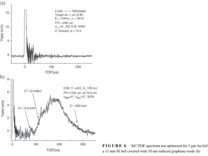
A further reduction of the Au foil thickness decreases ion acceleration instead of increasing it, a result expected because too lower thickness decreases the electron density emerging from the rear side reducing the value of the electric field driving ions. Figure 6a reports the SiC spectrum obtained irradiating a pure very thin Au foil, with 1 μm thickness and a little different laser condition, thus using not optimized irradiation condition, using FP = +250 μm and without the rGO superficial film deposited on both the Au foil sides. In this case, only the photopeak appears and no ions were detected at high and low energy. Such a result indicates that too low foil thickness and the absence of carbon layer in the surface injects too low electrons in the rear face of the foil producing a low electron density and consequently a low electric field driving the ion acceleration. Probably, this bad result is due to the high laser light reflectivity of the gold surface and to a not optimal thickness of the target, too low, in agreement with the literature.[31]
Figure 6b reports another example of plasma characterization obtained using laser irradiation of an 11 μm Ni foil covered in both faces with 10 nm rGO graphene film, using a focal position FP = +50 μm. The spectrum reports the fast and very high photopeak, with a duration of about 4.5 ns due to the X-ray emissions from the laser-generated plasma, triggering the TOF temporal data, followed by a background of fast electrons and of a slower high and large peak due to the ion detection at different velocities. The minimum TOF value of the detected electrons signal separated from the photopeak occurs at about 7 ns, corresponding to a kinetic energy of about 30.3 keV, but it does not exclude the presence of faster (relativistic) electrons
0 100 200 0 5 10 15 # 249, TEK00002 Target Au 1 m (5-B) EL= 124mJ, = 30 fs FP= +250 m inc=0°, SiC 8 @ -500V 0° forward, d = 74.5 Yield (mV) TOF(ns)
(a)
0 100 200 300 0 2 4 6 8 C+ = 500 keV C/Ni 11 m/C, EL 135 mJ FP=+100 m, d=74,5 cm det=0°, inc=0°, SiC8Yield (mV) TOF(ns) H+= 510 keV C6+ =3.0 MeV
(b)
F I G U R E 6 SiC-TOF spectrum not optimized for 1 μm Au foil (a) and for a 11 mm Ni foil covered with 10 nm reduced graphene oxide (b)
arriving at the detector during the photopeak detection. The minimum TOF value of the detected ions occurs at about 75 ns, which corresponds to protons at a maximum kinetic energy of 500 keV. The high ion peak yield due to carbon ions indicates a maximum carbon kinetic energy of about 3.0 MeV, as a result of the higher ion charge state acceleration. Assuming the proton acceleration of 500 keV to be representative of the ion acceleration per charge state, it means that the maximum C charge state is 6+, and that of C1+has 0.5 MeV kinetic energy, in good agreement with the literature and with the CBS deconvolution here
not reported for simplicity.
Comparing the results of the SiC spectra using 10 μm Au and 11 μm Ni foils, we can observe that, despite the higher atomic number of Au, the maximum proton energy is higher in Ni (510 keV) instead of that in Au target (145 keV). Thus, although Au has a higher electron density with respect to Ni, its high thickness probably increases the electron energy loss and scattering of the accelerated electrons with respect to Ni decreasing the forward ion acceleration. Thus, for Au foils, obtained results indicated that the foil thickness of about 10 μm is too thick to produce a good high ion acceleration and that a better acceleration is obtainable using about 2.0 μm thickness, such as for Ta foil. Measurements on 2 μm Au foil, in fact, have given a maximum proton energy of 750 keV and an equivalent plasma temperature of 38 keV.
The obtained results can be summarized now and it gives interesting information on the TNSA ion acceleration mechanism under the conditions of the used laser irradiation, that is using a low laser contrast of only 10−5 with a very high pre-pulse
energy and duration, very lower with respect to the normal conditions, which are five orders of magnitude higher, due to the main pulse about 1010times higher with respect to the pre-pulse.
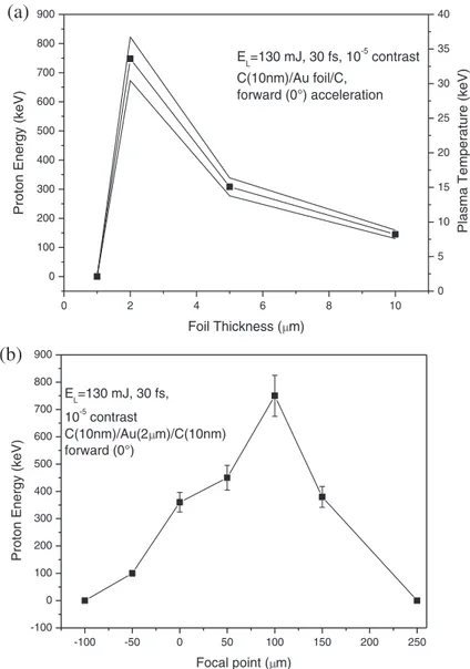
Figure 7a reports the maximum proton acceleration as a function of the foil thickness for the gold target obtained by our experimental data. The analysis of reported data indicates that the maximum proton energy values is 750 keV obtained using a 2 μm Au foil, covered by 10 nm rGO in both faces. Measurements of proton energy are reproducible and are affected by a mean error of about 10%, as indicated by the error bars in the plots.
It is possible to observe that the optimal foil thickness for the proton acceleration is 2.0 μm with a focal positioning of +100 μm. At lower and higher thickness, the proton energy decreases decreasing the electric field driving the ion acceleration due to the lower electron density transmitted to the rear side. Using 1-μm Au foil, the full-generated electrons from the laser are too low, and using 5 μm Au foil, the electron energy loss and scattering decrease the transmitted electrons to the rear side of the target, in both cases decreasing the forward proton energy acceleration, in agreement with the literature.[24,31]
F I G U R E 7 Maximum proton energy and plasma temperature versus Au foil thickness (a) and proton energy versus focal position (b)
0 2 4 6 8 10 0 100 200 300 400 500 600 700 800 900
Proton Energy (keV)
Foil Thickness ( m) EL=130 mJ, 30 fs, 10-5 contrast C(10nm)/Au foil/C, forward (0°) acceleration
(a)
0 5 10 15 20 25 30 35 40Plasma Temperature (keV)
-100 -50 0 50 100 150 200 250 -100 0 100 200 300 400 500 600 700 800 900 EL=130 mJ, 30 fs, 10-5 contrast C(10nm)/Au(2 m)/C(10nm) forward (0°) Prot on Energy (keV) Focal point ( m)
(b)
Changing the laser focal point (FP) changes also the laser spot size on the target and consequently the ion acceleration as a result of different effects. The main of these effects concerns the laser spot size on the target surface, which increases if the laser light is not focused on the target surface, enhancing the irradiated area and the number of surface accelerated electrons. Such electrons can be injected in the foil and transferred to the rear side of the foil to contribute to the electric field driving the ion acceleration. A second studied effect concerns the possibility to use a focal point in front of the target surface at about 10–100 μm distance (negative FP values), in order to focalize laser on the pre-plasma produced in front of the target. In general, this operation permits to induce effects of laser self-focusing due to the further laser focalization in the high refraction index of the pre-plasma vapour. The self-focusing may reduce the spot size to values comparable with the laser wavelength, enhancing the pulse intensity and consequently the electric field driving the forward ion acceleration, in agreement with the literature.[11]However, the self-focusing effect, although searched in our experiment by changing micrometrically the FP distance and recorded by measuring the consequent proton acceleration energy, was not generated with the used set-up.
Figure 7a reports in the right Y axes the equivalent plasma temperature evaluated from the CBS-like function. For the gold foils, the maximum temperature of 37 keV is found at the higher proton acceleration of 750 keV. The temperature has a value below that expected using Equation (2), probably for the effect of the high pre-pulse generating a pre-plasma and the main laser pulse energy loss in this pre-plasma as well as in the solid target.
Figure 7b reports some results obtained by measuring the maximum proton acceleration versus the focal position of the laser in the case of the 2 μm Ta and Au target irradiation. The plot indicates that the maximum acceleration is obtained using FP = +100 μm, that is focusing 100 μm inside the target, in agreement with similar measurements performed using a high fs contrast laser.[8]At this point, the laser intensity decreases of two orders of magnitude lower (1016W/cm2) due to the higher spot size on the target, but the number of accelerated electrons from the surface increases of about two orders of magnitude and the pre-pulse energy decreases to a value at which the solid target is not completely destroyed. Under such conditions, the fs
main laser pulse interacts with the overdense target and the pre-pulse effect is minimized. Due to such conditions, the detectors show a significant increment in the forward ion acceleration, which arrives up to 750 keV for the Au target. Thus, the electron density of the plasma and the consequent electric field of the ion acceleration increase not only because of an increase in the irradiated target surface but also because the main pulse hits a solid target at overcritical density.
4
D I S C U S S I O N A N D C O N C L U S I O N S
The pre-pulse plays an important role in the main fs laser interaction with the matter. In order to enhance the ion acceleration, it should be narrow in time and transport low energy as much as possible. This guarantees that the main fs pulse irradiates a solid target, accelerating electrons from the target surface and developing a high electric field driving the forward ion acceleration. When the pre-pulse, instead, has a long time duration and transports high energy, its action produces a disruption of the solid foil and the formation of a pre-plasma, which is emitted in the backward direction at supersonic velocity in a vacuum. Thus, the successive arrival of the main fs pulse interacts with this plasma having a density lower than a solid matter and produces a weak electric field of forward ion acceleration.
In order to obtain high forward ion acceleration (above 1 MeV per charge state), the pre-pulse must be very limited in time and energy, that is the laser contrast must be high, of the order of 10−(8–10), as reported in the literature.[4,5,29]Instead, the use of
a 10−5contrast and 10 ps pre-pulse duration indicates that the main pulse will produce only a low proton acceleration, generally
below 1 MeV in energy.
The experiment confirms that the proton acceleration obtainable using a low laser contrast, of about 10−5, generally is below
1 MeV under the used irradiation conditions and with the used target thicknesses and compositions. This result can be obtained optimizing the target thickness with about 2 μm in thickness and using a focal position positive of about 100 μm inside the target. In contrast, literature reports that energies above 1 and 10 MeV or higher can be obtained increasing the laser contrast at about 10−10, as recently obtained in experiments with a very similar laser and targets.[8,32]
However, by changing the shape of the main pulse, using for example a low laser contrast and a double main pulse separated by a few ps, or using a pedestal pulse intensity comparable with the main laser pulse, or using a negative focal position, focusing on the pre-pulse zone, may be that higher proton acceleration can be obtained, as that reported in recent literature.[15]
The important result of this contribution concerns the aspect that not only protons are accelerated at low laser contrast but also carbon ions, excluding the heavier ions. Thus, obtained results indicate that using the presented set-up not only protons but also other light elements, such as carbon ions, can be accelerated in the TNSA regime, in contrast with the data reported in the literature.[18].
The results reported in this article are relative to the forward SiC detector placed at 0◦, that is along the normal to the target surface, and not to the other detectors and higher angles employed during the experiment. This detection method, in fact, is sufficient to give information on the maximum ion acceleration in the forward direction. Lower proton energies were measured with the detectors placed at angles within ±30◦from the normal direction.
Work is in progress in order to compare the results with that obtained using the other detectors, including IC, Thomson parabola spectrometer, and backward SiC detectors. Preliminary results obtained by the analysis of different detectors confirm that: (a) the forward ion emission has a narrow angular distribution (less than ±30◦ for protons); (b) the high carbon charge states have an angular distribution lower than protons (less than ±15◦); and (c) the backward ion acceleration is less energetic with respect to the forward one, in agreement with the literature.[33]
The measured proton and carbon energies indicated that the charge states are shifted in energy proportionally to the charge state with energy proportional to that of the proton acceleration. Hence, for protons and carbon ions, it seems that the CBS-like distribution approach can be applied with success, indicating that their distributions follow a Boltzmann shape, which is shifted towards higher energy increasing the ion charge state.[28]
The TOF ion spectra indicate the presence of protons and carbon ions from all the experiments and the absence of heavy metallic ions coming from the metal of the target. The TNSA mechanism is effective to drive the acceleration of the rear surface of light elements, such as protons and carbon species, and not of the heavy ions, which have high inertia to be accelerated during the laser pulse duration (a few tens of fs). Their slow velocity does not permit to subject such ions to the fast and high electric field developed in the rear side of the target foil.
A C K N O W L E D G M E N T S
Authors thank the Laser-Lab Europe for supporting the proposed Project at ECLIPSE laser, Celia, Bordeaux, France, and all the staff of the laser laboratory for their collaboration given to the measurements acquisition. The research was supported by
Università degliStudi di Messina, Research & Mobility Project No. 74893496, and by CANAM (Center of Accelerators and Nuclear Analytical Methods) infrastructure LM 2015056 P108/12/G108 (Project No. 16-05167S).
R E F E R E N C E S
[1] M. Rosinski, J. Badziak, F. P. Boody, S. Gammino, H. Hora, J. Krasa, L. Laska, A. M. Mezzasalma, P. Parys, K. Rohlena, L. Torrisi, J. Ullschmied, J. Wolowski, E. Woryna, Vacuum 2005, 78, 435.
[2] K. M. Hofmann, S. Schell, J. J. Wilkens, J. Biophoton. 2012, 5, 903.
[3] L. Torrisi, S. Cavallaro, M. Cutroneo, L. Giuffrida, J. Krasa, D. Margarone, A. Velyhan, J. Kravarik, J. Ullschmied, J. Wolowski, A. Szydlowski, M. Rosinski, Rev. Sci. Instrum. 2012, 83, 02B11.
[4] J. Fuchs, P. Audebert, M. Borghesi, H. Pépin, O. Willi, C. R. Phys. 2009, 10, 176.
[5] A. Macchi, M. Borghesi, M. Passoni, Rev. Mod. Phys. 2013, 85, 751. https://doi.org/10.1103/RevModPhys.85.751.
[6] M. Kaluza, J. Schreiber, J. J. Honrubia, M. I. K. Santala, G. D. Tsakiris, K. Eidmann, J. Meyer-ter-Vehn, K.J. Witte, in 31st EPS Conf. on Plasma Phys., London, 2004 ECA Vol.28G, O-2.28.
[7] T. Ceccotti, A. Levy, H. Popescu, F. Reau, P. D'Oliveira, P. Monot, J. P. Geindre, E. Lefebvre, P. Martin, Phys. Rev. Lett. 2007, 99, 185002. [8] L. Torrisi, M. Cutroneo, M. Rosinski, J. Badziak, P. Parys, J. Wołowski, A. Zara´s-Szydłowska, A. Torrisi, Contrib. Plasma Phys. 2019, 59, 1. [9] D. Khaghani, M. Lobet, B. Borm, L. Burr, F. Gärtner, L. Gremillet, L. Movsesyan, O. Rosmej, M. E. Toimil-Molares, F. Wagner, P. Neumayer,
Sci. Rep. 2017, 7, 11366.
[10] L. Torrisi, L. Calcagno, D. Giulietti, M. Cutroneo, M. Zimbone, J. Skala, Nucl. Instrum. Methods Phys. Res. B 2015, 355, 221.
[11] L. Laska, K. Jungwirth, J. Krasa, E. Krousky, M. Pfeifer, K. Rohlena, J. Ullschmied, J. Badziak, P. Parys, J. Wolowski, S. Gammino, L. Torrisi, F. P. Boody, Laser Particle Beams 2006, 24, 175.
[12] A. Lubcke, A. A. Andreev, S. Hohm, R. Grunwald, L. Ehrentraut, M. Schnurer, Sci. Rep. 2017, 7, 44030. [13] J. E. Crow, P. L. Auer, J. E. Allen, J. Plasma Phys. 1975, 14, 65.
[14] L. Torrisi, Phys. Plasma 2017, 24, 023111.
[15] K. Markey, P. McKenna, C. M. Brenner, D. C. Carroll, M. M. Gunther, K. Harres, S. Kar, K. Lancaster, F. Nurnberg, M. N. Quinn, A. P. L. Robinson, M. Roth, M. Zepf, D. Neely, Phys. Rev. Lett. 2010, 105, 195008.
[16] M. Aliofkhazraei, N. Al, W. I. Milne, C. S. Ozkan, S. Mitura, J. L. Gervasoni Eds., Graphene Science Handbook – Electrical and Optical Properties, CRC Press, Taylor & Francis, Boca Raton 2016.
[17] L. Torrisi, L. Silipigni, M. Cutroneo, Vacuum 2018, 153, 122.
[18] D. Batani, G. Boutoux, F. Burgy, K. Jakubowska, J. E. Ducret, Phys. Plasmas 2018, 25, 054506.
[19] M. Cutroneo, P. Musumeci, M. Zimbone, L. Torrisi, F. La Via, D. Margarone, A. Velyhan, J. Ullschmied, L. Calcagno, J. Mater. Res. 2012, 28, 87.
[20] L. Torrisi, A. Sciuto, A. Cannavò, S. Di Franco, M. Mazzillo, P. Badalà, L. Calcagno, J. Electron. Mater. 2017, 46, 3. [21] L. Torrisi, A. Cannavò, JINST 2016, 11, 1.
[22] D. Wang, Y. Shou, P. Wang, J. Liu, C. Li, Z. Gong, R. Hu, W. Ma, X. Yan, Sci. Rep. 2018, 8, 2536.
[23] L. Torrisi, D. Margarone, L. Laska, J. Krasa, A. Velyhan, M. Pfeifer, J. Ullschmied, L. Ryc, Laser Particle Beams 2008, 26, 379. [24] M. Borghesi, Nucl. Intrum. Methods Phys. A 2014, 740, 6.
[25] M. Cutroneo, A. Macková, V. Havranek, P. Malinsky, L. Torrisi, M. Kormunda, M. Barchuk, J. Ullschmiedfand, R. Dudzakf, JINST-PPLA
2016, 11, 1.
[26] J. Ziegler, SRIM-The stopping and range of ions in the matter, actual website 2019, http://www.srim.org/ [27] J. H. Bin, A. L. Lei, L. H. Cao, X. Q. Yang, L. G. Huang, M. Y. Yu, W. Yu, Phys. Plasmas 2009, 16, 043109. [28] L. Torrisi, Radiat. Effect. Defects Solids 2016, 171, 34.
[29] M. Roth, M. Schollmeier, in Proceedings of the CAS-CERN Accelerator School: Plasma Wake Acceleration, Geneva, Switzerland, 2014 (Ed: B. Holzer), CERN-2016-001 2016.
[30] S. C. Wilks, W. L. Kruer, M. Tabak, A. B. Langdon, Phys. Rev. Lett. 1992, 69, 1383. [31] L. Torrisi, Optics Laser Technol. 2018, 99, 7.
[32] A. Higginson, R. J. Gray, M. King, R. J. Dance, S. D. R. Williamson, N. M. H. Butler, R. Wilson, R. Capdessus, C. Armstrong, J. S. Green, S. J. Hawkes, P. Martin, W. Q. Wei, S. R. Mirfayzi, X. H. Yuan, S. Kar, M. Borghesi, R. J. Clarke, D. Neely, P. McKenna, Nat. Commun. 2018, 9, 724. [33] L. Torrisi, M. Cutroneo, J. Ullschmied, Phys. Plasmas 2017, 24, 043112.
How to cite this article:Torrisi L, Cutroneo M, Torrisi A. Protons and carbon ions acceleration in the
target-normal-sheath-acceleration regime using low-contrast fs laser and metal-graphene targets. Contributions to