DOI 10.1007/s12369-016-0349-8
Enabling Global Robot Navigation Based on a Cloud Robotics
Approach
Raffaele Limosani1 · Alessandro Manzi1 · Laura Fiorini1 · Filippo Cavallo1 · Paolo Dario1
Accepted: 8 March 2016
© The Author(s) 2016. This article is published with open access at Springerlink.com
Abstract In the future, social robots will permeate our daily life. An autonomous robot that has to move among different buildings needs to manage huge amount of data, as a consequence it is clear that the configuration of the navi-gation system becomes hard to manage. This paper presents a system, based on a cloud robotics paradigm, conceived to allow autonomous robots to navigate in indoor environ-ment, which are not known a priori. The environment is divided into sub-maps and all the necessary information and the topological representation of the world, are stored into a remote cloud infrastructure. By means of specific environ-mental tags, composed of a set of ARTags and QR codes, the robot gets the access to the cloud service and it is able to update its navigation configuration in a dynamic and auto-matic way. Experiments have been conducted in order to choose an appropriate marker dimension and to demonstrate the feasibility of the proposed procedure.
Keywords Robot navigation· QR code · AR tag · Cloud robotics
Raffaele Limosani, Alessandro Manzi and Laura Fiorini have contributed equally to this work.
B
Alessandro Manzi [email protected] Raffaele Limosani [email protected] Laura Fiorini [email protected] Filippo Cavallo [email protected]1 The BioRobotics Institute, Scuola Superiore Sant’Anna, Viale Rinaldo Piaggio, 34 56025 Pontedera (PI), Italy
1 Introduction
A recent survey shows that more than the 50 % of worldwide people live in urban area (3.3 billion). By 2030 this per-centage is destined to increase reaching 5 billion [1]. With this rapid boost, the cities face a variety of risks, problems and opportunities. In this context governments and public institutions introduce the concept of Smart City facing the growing demanding for more livable city. During recent years this paradigm has taken a new dimension of integra-tion of technology, such as robotic and ICT soluintegra-tions, to build infrastructures and to design innovative services for citizens [2]. Recently technology has permeated in our daily life, citizens are connected any time and anywhere to internet resources and to social networks by means of their mobile devices [3], indeed about 4 billion people has a mobile phone [4]. The concept of smartness associated to the technology aspects implies the equipment of homes, buildings, and other large areas of interest (airports, universities, industries) with smart devices such as companion robots, sensor networks and mobile devices [5]. These hardware agents should highlight the smart city performance in terms of environmental mon-itoring, surveillance, mobility and transportation of goods. However technology is not the only key aspect of the smart city, since people and institution are essential too [2]. This means that hi-tech solutions should be designed and imple-mented considering also the social dimension; they need to be designed for the citizens and around the citizens, in a town-center design approach. Smart citizens need mod-ularity and flexibility of services, the technology should be ease to use with low costs to be sustainable from an economic point of view. Moreover, the citizen wants the con-tinuity of the service. It has to accompany him during the daily activity through multiple environments in a transparent modality.
Considering advanced robotics, researches are mainly focused on the development of solutions which operate in a single environment. However, imagining a futuristic sce-nario which contains a multitude and heterogeneous kinds of autonomous robots employed to conduct varied and continu-ative services, such as goods transportation, within the same or among different buildings, new and challenging issues arise. How can an autonomous robot move in complex and wide environments efficiently? Up to now, environmental maps are stored in the robot: consequently, the configuration of the navigation system becomes hard to manage, since it needs a huge amount of data, increasing the storage burden and reducing the search efficiency of the planning algorithms. What if autonomous robots would be able to get environ-ment maps dynamically without any additional configuration procedures? In order to do that, all the maps information and the topological representation of the world, which contains the relations between places, should be stored elsewhere. In 1993 Prof. Inaba introduced the concept of the “Remote-Brained Robotics” [6] to improve the usability of standalone robots distributing part of the software out of the robot. This idea was based on the separation between the brain and the body to connect standalone robots to a high level remote control system. This innovative design opened the way to the use of parallel powerful computers and the provision of complex services to user that robots alone were not able to provide. Networked robotics [7] exploit this paradigm integrating stand-alone robots with sensor networks and dis-tributing the robot processing and control capabilities over a set of remote and dedicated servers. In this paradigm sen-sor networks cooperate with robots to extend their sensing capabilities to provide more complex services to all citizens. Nevertheless networked robots show some limitations related to the continuity of service [8], the flexibility and scalability of resources [9] and the bandwidth [10].
Cloud Robotics paradigm is “the combination of cloud computing and robotics” [11]. This concepts is “not related to a new kind of robot but to the way in which robots access and store information”. Cloud robots are recently defined as “any robot or automation system that relies on either data or code from a network to support its operation, where not all sensing, computation and memory is integrated into a single standalone system” [12]. The benefits to distrib-ute part of the capabilities among a group of agents over a cloud infrastructure rely on big data, powerful comput-ing resources, collective learncomput-ing and use of crowd-sourccomput-ing [13]. Cloud computing represents an interesting step change for robotics to become really used in consumer and assisted living applications and markets. It provides the opportunity to exploit user-centered interfaces, computational capabilities, on-demand provisioning services, and large data storage with minimum guaranteed quality of services (QoS), scalability, and flexibility [14]. Using cloud resources, robotic services
can be modulate according to the single user needs. Cloud can provide robots a vast resources of data such as environ-mental maps that are not possible to store on-board [15]. In this way a single robot with low computational capabilities can potentially retrieve from the cloud any maps to navigate in unknown buildings and districts with no additional con-figuration procedures. Furthermore a robot can upload new maps sharing the knowledge with other agents.
Therefore, this article proposes a method to enable global robot navigation based on a cloud robotics paradigm. The proposed system allows robot to retrieve from the cloud the appropriate maps to navigate in unknown environments. The paper is structured as follows. Section2presents the related work on the use of environmental tag for robotic navigation and localization, while Sect.3gives an overview of the pro-posed system. The Sect.4details the implementation aspects, while experiments are summarized in the Sect.5. At the end, Sect.6concludes the paper.
2 Related Works
During the last few years, several researches show how land-marks and environmental tags can be used to help companion robots in navigation and localization procedures. Particularly, in [16] authors describe a tour guide low-cost robot using a DFRobot L298 and a smartphone. The robot is programmed to stay 30 cm from the wall while a custom algorithm per-forms the obstacle avoidance. The system uses two different tags, one (a sequence of three dots) is used to control and adjust the robot velocity, while a QR tag [17] is used to give the information. However the information contained in the tag are very simple (“turn left”, “turn right”) without a link to an accurate representation of the environment, therefore the robot does not know its position.
Kobayashi et al. [18] propose a self-localization of mobile robot by self-contained 2D barcode landmark for kidnapping problem without involving any external resources (i.e., data-base). They use a Pioneer 3-AT equipped with an analog camera to detect QR: the information detected are used by the on-board algorithm to self-localization by means of geo-metrical analysis. Nevertheless this system presents some limitation due to the accuracy, the precision and the process-ing time related to the software for detectprocess-ing 2D code.
In [19] the authors present a realtime 2D code based localization for indoor robot navigation. They describe and test a multi-threshold averaging, light gradient compensation and neighbourhood search techniques to enhance the perfor-mances of the ARToolKitPlus [20] software library, used to calculate camera position and orientation relative to physical markers.
Takahashi et al. [21] design and implement a naviga-tion method in unknown environments. In particular, authors
focus their efforts in shelters context, where it is difficult to prepare a complete map of shelters and to operate robots autonomously due to dynamical changes of the environment. They use two different tags (AR and QR) and test the system in a nursing home. The AR marks are used as a reference point, while the QR encodes a low-level sequences of move-ments (“forward”, “turn left”, “turn right”) to reach the next point.
Zhang et al. [22] present a system based on QR tags for the initial localization procedure of a service robot inside home. They mainly focus on the comparison between differ-ent searching methodologies. Okuyama et al. [23] use the QR tags in order to reduce the localization error of the vSLAM algorithm.
In the aforementioned works, the landmarks are used to provide local spatial information or to encode simple com-mands, but especially the QR codes can be used to codify any type of resource identifier. They provides robot with the access to the cloud.
Furthermore, even if the current literature is rich of exam-ples about robots in real or realistic environments, as [24,25], at the best of our knowledge this is the first attempt to include referential markers to provide information in a robotic sce-nario in real environments.
Therefore, in this paper, the authors propose a system for robot navigation in unknown environments based on a cloud robotics paradigm. The environmental maps are divided into sub-maps and stored into a cloud storage. The robot can access to these remote resources in a Software as a Service modality (SaaS), it retrieves the maps it needs only when needed. The system uses sub-maps in order to reduce prob-lems related to the big-maps managing. Additionally, in this proposed architecture, the robot has all the navigation capa-bilities on-board to avoid problems concerning time delays, communications and networks performance [26–28], thus it is able to safely navigate also when there are communica-tions problems. Environmental tags are linked with cloud resources. Hence, the robot can retrieve the maps and the topology of the environment to navigate autonomously. In fact the cloud resources contain the information on the other environmental tags and the description of how the maps are linked, so the robot can easily access to the other tags. As a consequence, it becomes aware of the surrounding environ-ments without any previous configuration.
Additionally, cloud resources allow robots to use the pro-posed SaaS in a pay-per-use modality, so this solution is cheaper then the same solutions with a local server, where the users have to pay the system even when they do not use it [9].
3 System Overview
The proposed system aims to provide a dynamic way to automatically configure mobile robots in order to allow the
navigation into complex and wide indoor environments that are not known a priori. To achieve this objective, the suitable information needed for autonomous navigation have to be stored into remote and accessible locations apart from the platforms. In addition, a reliable mechanism to obtain such kinds of data must be provided.
The environment (i.e., a wide building) is divided into sub-maps that are identified by a Map Identifier (Map ID) that is unique. It contains a Building Code plus a Map Code.
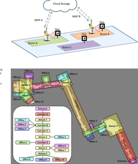
The proposed system relies on three main modules: the environmental tags, a Cloud SaaS and a Maps Supervisor. The environmental tags are particular landmarks conceived to provide both spatial and remote resource information to the robots. The Cloud SaaS stores all the information about the environments, i.e., the maps and some configuration files describing the topology of the areas and also manages these resources. The Maps Supervisor, which links the robot to the remote resources, takes the output from the the tag detec-tion module and updates the map and the posidetec-tion of the mobile platform; these operations are performed on the robot in coordination with the navigation stack. The Machine-to-Cloud communication allows the proper access to the Machine-to-Cloud platform to take advantage of the map storage service [29]. The Fig.1shows how different mobile platforms can use the environmental tags to retrieve all the information needed for the autonomous navigation. The Cloud SaaS, which stores the resources in a database, manages the accesses to them. This integration of physical agents with the cloud platform empowers the robot to outsource part of the storage in the cloud [13].
Each environmental tag encodes the location of the cloud resource from which obtain additional information, and the aforementioned Map ID, composed by a Building Code plus a Map Code. The latter represents a link to the sub-map in which the robot is moving to. Therefore, the environmental tags can be seen as a sort of “portals” to the contiguous loca-tion. In details, the information retrievable from the Cloud SaaS are the following:
Image Map describes the occupancy state of each cell of the area with the color of the corresponding pixel. It fol-lows the Robot Operating System (ROS) [30] standard for 2-D map representation. See Sect. 4 for additional details.
YAML file contains several parameters, including the file name of the map, the cell resolution and the threshold for the occupancy probability.
Environmental tags list contains the information about the tags of the map, including both their positions inside the map and the linked Map ID. See Sect.4for additional details.
Topology graph describes the graph of the environments. It contains all the connections between sub-maps. This file
Fig. 1 Different mobile
platforms use the environmental tags to retrieve cloud resources needed for the autonomous navigation
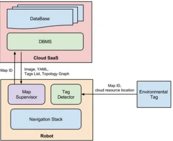
Fig. 2 The floor of the building
is represented with overlapping sub-maps. Looking at the tag placed at the entrance
(bottom-right), a robot retrieves the map of the Corridor A and the topology of the whole building (graph on the left)
is equal for all the areas of the building. The link between sub-maps are expressed through the Map IDs.
All the above data, except the topology, is referred to a specific Map ID (i.e., sub-map), which is unique for the building.
In order to clarify better how the system really works, in the remainder we depict an explicative scenario. Let consider a service robot that has to carry a box to the Office 7 of the building depicted in Fig.2. It arrives at the entrance of the building (bottom-right) and, reading the tag placed there, it
retrieves the Map ID and the cloud location that stores the additional resources describing the building. Now, the robot, contacting the Cloud SaaS, can download all the informa-tion relative to the approaching sub-map (i.e Corridor A). In particular, the Image Map and the YAML file needed for the navigation, and the environmental tags List containing the positions of all the tags placed in the sub-map. Then, it is able to update the map, its new position and to move to the next area. After retrieving information from Cloud SaaS, all the computation needed for navigation was performed on-board. The last information is about the Topology Graph of
the building, which expresses the connections between areas, by means of Map IDs (graph on the left of the Fig.2). Using a graph search algorithm, the robot computes the following path:
Corridor A→ Atrium 1 → Corridor B → Corridor C → Atrium 2 → Corridor D → Atrium 3 → Office 7
In this way, the robot knows how to reach its destination, so it retrieves the position of the tag that refers to Atrium 1. This process iterates again until the Office 7 is reached. As preliminary implementation, optimization of the process has not been investigated yet. On the way back, the robot already has all the maps and it does not need to download them again. In the above scenario, the Topology Graph is used only the first time at the entrance of the building. However, it is available from all the Tags of the environment and the robot can exploit this information anywhere. In this way, a robot is aware of the surrounding environment any time and anywhere.
4 Implementation
This section deepens the implementation aspects of the three modules that compose the proposed system: Cloud SaaS, environmental tag and Maps Supervisor (see Fig.3). The latter represents the link between the cloud service and the navigation stack of the robot. It feeds dynamically the nav-igation stack with new maps, new positions and new goals. It uses a Tag Detector module to retrieve the information in order to contact the Cloud SaaS.
Fig. 3 The system is composed by three modules. The Maps
Super-visor, running on the robot, a Tag Detector that retrieves the necessary information to download environmental data from the Cloud SaaS
4.1 Cloud SaaS
The cloud service stores all the environmental information and manages the accesses to its own resources. The Maps Supervisor module running on the robot, sends the Map ID to the Cloud SaaS location encoded in the environmental tag. Then, it receives the Image Map, the YAML file, the envi-ronmental tags list and the topology graph of the building. As introduced in Sect.3, the first two resources follow the ROS [30] standard for 2-D map representation. The Image Map describes the occupancy state of each cell of the world using the color of the corresponding pixel. Whiter pixels are free, blacker pixels are occupied, and pixels in between are unknown areas. Thresholds in the YAML file are used to divide the three categories. The possible image formats are multiple, it supports BMP, GIF, JPEG, PNG, PNM, TIFF, and many others. The YAML file contains several parame-ters such as the name of the image map, the resolution of the map in meters/pixel, the origin of the map (lower-left pixel) and the occupancy probability threshold. The environmental tags list contains all the marker position coordinates (x, y and yaw) relative to the obtained map and the Map Code of the “linked” sub-map. As an example, let consider the sub-map Corridor C of the Fig.4, the environmental tag list is: Map Code: Corridor C
{link: Room A, position: [x1, y1, yaw1]} {link: Room B, position: [x2, y2, yaw2]} If a robot is moving towards Corridor C and it has to go to Room A, it can get the coordinates of the Tag looking at the environmental tag list.
The last resource is the Topological Graph (see Fig.2). It is a file that stores all the connections between sub-maps in terms of Map Code and it is memorized by the Map Super-visor as an adjacency matrix.
From an implementation point of view, the cloud service consists of a MySQL relational Data-Base (DB) and a DB Management Software (DBMS). The DBMS manages DB entries and queries while the DB contains data from the connected robotic agents. The relative MySql relational is conceptually divided into three different parts, one related to the environmental maps (M), one to the robots (R), and one to the buildings (B). The entities and the attributes are described in the following way:
R = {RobotID#, Description, BuildingCode*} M = {MapCode#, ImageMap, YAML,
Tag List, BuildingCode*} B = {BuildingCode#, Topology Graph}
The entity R reports the list of robot allowed to use the service. It contains an ID which is the primary key, the robot description and the identification code of the building to
Fig. 4 Details of environmental
tag for each sub-maps. The tag list of the Corridor C maps contains the position of the Tags that links Room A and Room B
Fig. 5 A QR Code example, it encodes the cloud location, the building
code and the map code
which it belongs. The entity M reports the information regard-ing the maps (ImageMap, YAML file and the Tag List of available markers in the map). Furthermore, it reports the BuildingCodewhere the maps belongs to. The MapCode is the primary key of M. The building entity B reports the list of the buildings with the relative Topology Graph, which report the relation between the sub-maps.
The BuildingCode and the MapCode stored in the environmental tags allows robots, which are in R, to retrieve all the necessary information.
4.2 Environmental Tag
According to this system, the markers needs two main requirements. The possibility to encode data (i.e., Map ID and cloud resource location) and to provide spatial informa-tion (i.e., the relative posiinforma-tion between mobile platform and marker). The first property is easily obtained using the Quick-Response (QR) code [17]. The information are encoded as a text line containing the IP address of the machine that runs the cloud service, the zip-code and the address of the build-ing (Buildbuild-ing Code) and the Map Code. As an example, the QR in the Fig.5encodes the line “159.213.137.133, 56037, boccioni_1, CorridorA”.
Unfortunately, due to its complex pattern, QR codes have very short detection range. For this reason, it has been com-bined with the ARTag code [20], which is a fiduciary marker to support augmented reality. Basically, the information rep-resented in an ARTag are much more simple compared to QR code. This improves the detectability and reliability of the tag, enhancing at the same time the distance at which the tag can be read.
Some experiments (see Sect.5) have been conducted in order to select a suitable tag dimension that provides an acceptable detection range and enough encoding capability. Other tests have been carried out to evaluate the accuracy of the estimated position between the robot and the ARTag. Considering the results, a QR code with 29× 29 array size and a dimension of 6x6 cm for both the tags has been adopted. Environmental tags were disposed according to the divi-sion of the environment in sub-maps, at the overlapping area linking two different sub-maps, as depicted in Fig.4. Divi-sion in sub-maps has been performed according to the already present division of the environment, such as rooms, corridors, etc.
4.3 Robot
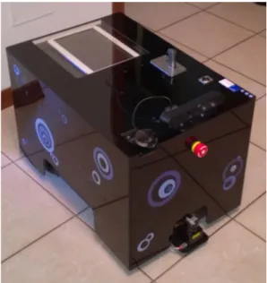
The system has been tested using the KuBo robot (Fig.6), a friendliness platform built upon the youBot (commercialized by KUKA [31]), equipped with a laser scanner and a depth camera (Asus Xtion Pro Live) [32].
KuBo is conceived as a platform with low computation capabilities that has to exploits cloud resources to carry out its tasks. The autonomous indoor navigation relies on the ROS navigation stack and uses the Dynamic Window Approach [33] for local planning and the Adaptive Monte Carlo [34] for indoor localization. In addition, a Map Supervisor and a Tag Detector module runs on the robot.
4.3.1 Map Supervisor
The Maps Supervisor module is the link between the cloud service and the navigation stack of the robot. Once the Tag Detector retrieves the tag information (Map ID and cloud resource information), the Maps Supervisor module is able
to send the Map ID to the Cloud Service and receives the Image Map, the YAML file, the environmental tags list and the topology graph of the building. The first two resources are used to update the map on the navigation stack, while the new position of the robot is calculated considering the position of the current tag, retrieved from the Tags List, and the relative distance calculated from the ARTag. The Topology Graph structure is memorized as an adjacency matrix and thanks to a graph search algorithm, it is used to calculate the path in terms of sub-maps in order to reach the destination. Looking at the environmental tag list, it knows the coordinates of the next tag that it has to read, so it provides the new goal to the navigation stack.
4.3.2 Tag Detector
The Tag Detector module is used to retrieve the information stored in the environmental tag (Map ID, cloud resource loca-tion) by means of RGB-D camera to perform the recognition. It is implemented in ROS and uses the following software libraries:
Fig. 6 The KuBo robot, built upon a youBot KUKA platform is used
for the experiments
ALVAR is used for the ARTag tracking. It is a software library for creating virtual and Augmented Reality (AR) applications. It has been developed by the VTT Techni-cal Research Centre of Finland and it is released under the terms of the GNU Lesser General Public License [35]. Differently for other library for ARTag detecting (as ARToolKit [20]), the ALVAR library combines image and depth information gathered from an RGB-D camera. ZBar for the QR code detection. It is an open source software suite for reading bar codes from various sources, such as video streams, image files and raw intensity sensors [36].
5 Experiments
The detection distance of the two types of markers depends of course by its size. In particular, concerning the QR, the larger the size more information can be stored. For this reason, a quantitative comparison between marker size and detec-tion distance has been carried out in order to evaluate an acceptable tag dimension. The Table1reports the maximum distance registered for the tag detection. Tests have been con-ducted considering 7 different sizes, ranging from 2× 2 cm to 8× 8 cm, of both QR and AR Tag. Evaluation also con-sidered the detection distance at difference angle of view; obtained results proved that the ARTag are easily detectable from different angles.
Since the detectability of a QR tag is related to its complex-ity, and this is related to the quantity of information stored, the tests have been carried out with the QR version 3 (array module 29× 29), version 4 (33× 33) and version 8 (49× 49). The AR codes have been detected using the ALVAR library, while the QR with the ZBar, using an Xtion Pro Live sensor as described in Sect.4.3.
Encoding the IP address and the Map ID in a QR, can produce a version 3 or version 4 QR type, according to the text length. Considering the test results, these type of markers with a dimension of 6× 6 cm are detectable from 0.47 and 0.43 m respectively. Combining the QR with an ARTag of the same size it is possible to enhance the detection distance up to 1.128 m. With these settings, the robot is able to detect the marker at a distance of 1.128 m and moving toward it until it is able to recognize the QR code at 0.47 m (Fig.7).
Table 1 Tag detection distance considering different marker size. QR version refers to its grid size: version 3 (29× 29), version 4 (33 × 33),
version 8 (49× 49). All the measurements for distance are in centimeters
Tag (cm) 2× 2 (cm) 3× 3 (cm) 4× 4 (cm) 5× 5 (cm) 6× 6 (cm) 7× 7 (cm) 8× 8 (cm)
QR version 3 <25 <25 27 37 47 56 60
QR version 4 <25 <25 26 35 43 51 53
QR version 8 <25 <25 <25 <25 32 37 37
robot frame x y ARTag frame y x distance for detecting QR code
tolerance on navigation goal
detecting ARTag step 1, step 2:
step 3: moving toward goal step 4: detecting QRcode
step 5: updating map
Fig. 7 Representation of the Tag Detection procedure. At∼1.2 m, the
robot is able to detect the ARTag, so it moves towards it to decode the QR Tag
Another test about the Tag Detection procedure has been conducted in order to evaluate its feasibility and precision. The procedure is the following:
1. the Maps Supervisor module of the robot detects an ARTag within 1.128 m from its position;
2. a reference system is built upon the position and orienta-tion of ARTag; in this way the goal posiorienta-tion is completely described by pose and orientation;
3. a goal is defined in this reference system based on the navigation stack tolerance and on the detectable distance of QR code (∼0.47 m). If we consider the navigation tolerance as a circumference centered in a [d, 0] with radius r , the maximum distance from the origin is[d +r]. As a result, considering the threshold distance for detect-ing the QR code of the environmental tag, the goal is set at 0.47—toler ance;
4. at a distance less than 0.47 cm, the QR code is detected;
Table 2 Tag detection distance considering different angle of view. All
the measurements for distance are in centimeters
Tag (cm) 0(◦) 30(◦) 45(◦) 60(◦)
ARTag (6×6) 112.8 112.5 112 90
5. the Maps Supervisor contacts the Cloud SaaS and down-loads all the environmental information. The navigation stack is uploaded with the new map. The position of the robot is updated according to the position of the Tag pro-vided by the environmental tags list using a initial value of covariance equals to 1.0 m.
The procedure was successfully tested for n = 15 trials with a complete reliability of 100%. However, the procedure did not take in account the presence of obstacles near the tag locations; the space in front of the markers was considered always free.
The procedure has been tested with a mobile robot running the ROS navigation stack and mounting an RGB-D camera with a well-light environment. The system is conceived to work in indoor working environment, so tests in different and worse condition are out of the scope of this work.
Experiments have showed that at the QR detection dis-tance, around 50 cm, the accuracy of the ALVAR library is less than 2 cm (distance measured 51.21± 0.78 cm), which is a suitable value for the localization algorithm.
Additional tests have been conducted in order to estimate the reduction of the maximum detectable distance for ARTag changing the field of view (see Table2). With an angle of view of 60◦the maximum tag detection distance has a reasonable value of 0.90 m.
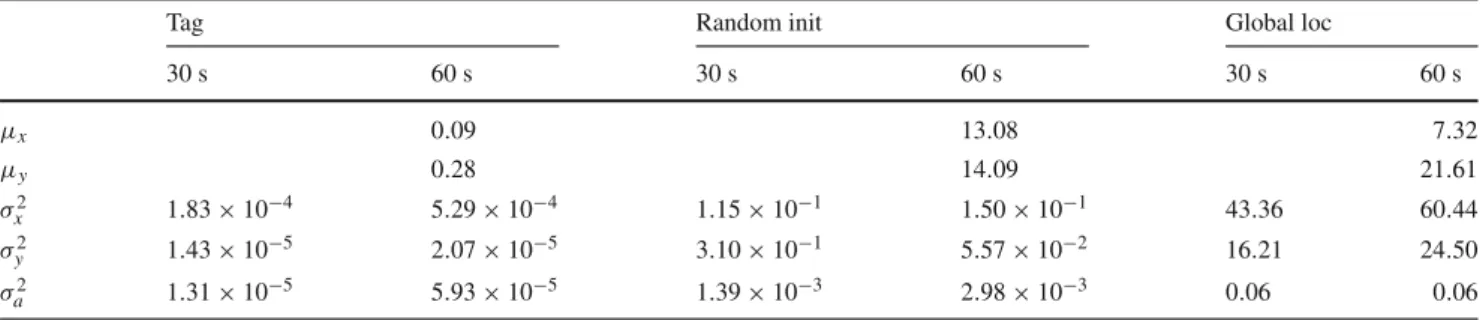
The use of these Tags helps also with the “wake-up robot problem”, i.e., when a robot is moved to an arbitrary location and put to operation. Tests have been carried out to estimate the resulting value of localization and convergence time of the process. The Table3shows an experiment with 3 different robot initialization: using Tag, using a random value in the map as initialization and using global localization service of the ROS AMCL algorithm. Values refer to the result of localization process after 60s (reported as mean error on x and y coordinates) and to the average of the variances after 30 and 60 seconds over 15 trials. Results depicted in Table3 highlight the benefits in the use of environmental tag both in error on localization and in time of convergence.
Table 3 Results from three different method of initialization of
local-ization algorithm: using a referential Tag, using a random pose value in the map and using the global localization service, which spread all the
particles of localization algorithm over the map. Results are depicted as mean value (pose estimated) after 60s and as value of variances after 30s and 60s, in order to show the status of convergence
Tag Random init Global loc
30 s 60 s 30 s 60 s 30 s 60 s μx 0.09 13.08 7.32 μy 0.28 14.09 21.61 σ2 x 1.83 × 10−4 5.29 × 10⁻⁴ 1.15 × 10⁻¹ 1.50 × 10⁻¹ 43.36 60.44 σ2 y 1.43 × 10⁻⁵ 2.07 × 10⁻⁵ 3.10 × 10⁻¹ 5.57 × 10⁻² 16.21 24.50 σ2 a 1.31 × 10⁻⁵ 5.93 × 10⁻⁵ 1.39 × 10⁻³ 2.98 × 10⁻³ 0.06 0.06
6 Conclusions
The proposed system is conceived to allow autonomous robot to navigate in indoor environment, which are not known a pri-ori. By means of specific environmental tag, that is a set of ARTag and QR code, and Cloud resources, a mobile plat-form retrieves the necessary inplat-formation, such as maps and building topology, in a dynamic and automatic way without pre-configuring its navigation stack. The use of smaller maps, for wide and complex environments, reduces the processing time of the inner global planner of the navigation stack. Each sub-map is virtually connected through the environmental tags, which represent a sort of “portal” for the adjacent area. In addition, the use of the ARTag to recover the localiza-tion errors, reduces the well-know “wake-up robot problem”, i.e., when a robot is moved to an arbitrary location and put to operation. Using the described system and starting the robot in front of an environmental tag, the AMCL algorithm can be initialized with a value of covariance equal to 1.0 m. Furthermore, the presence of marker in the environment enhance the performance of the localization algorithm. As proof of these sentence, tests were performed in long cor-ridor, where clues for AMCL algorithm were repeated (e.g. distance from the side walls): adding noise on the odometry, the localization process is not able to localize the platform and the localization error increase as the distance traveled; in the presence of referential markers, the error is reset every time a new marker is met. Tests have been performed using an AMCL algorithm based on minimum 100 and maximum 5000 particles, and updated after 0.2m of distance trav-eled.
The tag detection mechanism relies on depth cameras, which are extremely cheap and very common in robotics nowadays. Our implementation is focused on bi-dimensional maps but can be easily expanded to 3-D environmental maps. The use of artificial markers imposes to modify the envi-ronment, which is of course not always desirable. One of our next works is about the use of scene recognition techniques in order to identify features to use as “portals” instead of QR codes. Another future topic is the use of multiple robots that contribute to modify Cloud resources to improve the already stored information.
Considering a futuristic scenario, in which robots will be able to move autonomously in Smart Cities, it is clear that these platforms need a standard way to represent the world. The Cloud represents a powerful mechanism that allows the sharing of the knowledge. With the pro-posed system, heterogeneous robots can dynamically access information about the environment through artificial land-marks.
Acknowledgments This work was supported by the EC Seventh Framework Programme (FP7/2007-2013) grant agreement no. 288899 Robot-Era.
Compliance with ethical standards
Conflict of interest The authors declare that they have no conflict of interest.
Human and animal rights Research didn’t involved Human Partic-ipants and/or Animals.
Open Access This article is distributed under the terms of the Creative Commons Attribution 4.0 International License (http://creativecomm ons.org/licenses/by/4.0/), which permits unrestricted use, distribution, and reproduction in any medium, provided you give appropriate credit to the original author(s) and the source, provide a link to the Creative Commons license, and indicate if changes were made.
References
1. United Nation Population Found (2015) official website: www. unfpa.org, visited on
2. Nam T, Pardo TA (2011) Conceptualizing smart city with dimen-sions of technology, people, and institutions, In Proceedings of the 12th annual international digital government research confer-ence: digital government innovation in challenging times, ACM, pp. 282–291
3. Our Mobile planet, think with google. http://think.withgoogle. com/mobileplanet/it/
4. Arup (2011) Urban Life, The smart solution for a city report avail-able at:http://www.arup.com
5. Balandin S, Moltchanov D, Koucheryavy Y (2008) From smart homes to smart cities: opportunities and challenges from an indus-trial perspective. In: Balandin S, Moltchanov D, Koucheryavy Y (eds) Next generation teletraffic and wired/wireless advanced net-working. Springer, Berlin
6. Inaba M (1993) Remote-brained robotics: interfacing Al with real world behaviors, In: Proceedings of 1993 international symposium on robotics research
7. Sanfeliu A, Norihiro H, Saotti A (2008) Network robot systems. Robot Auton Syst 56(10):793–797
8. Kamei K, Nishio S, Hagita N (2012) Cloud networked robotics. IEEE Netw 26:28–34
9. Abidi F et al. (2013) Cloud servers vs. dedicated servers a survey. In: Innovation and technology in education (MITE), 2013 IEEE international conference in MOOC. IEEE
10. Hu G, Tay WP, Wen Y (2012) Cloud robotics: architecture chal-lenges and applications. IEEE Netw 26:21–28
11. Kuffner JJ (2010) Cloud-enabled robots. In: IEEE-RAS interna-tional conference on humanoid robotics, Nashville
12. Kehoe B, Patil S, Abbeel P, Goldberg K (2015) A survey of research on cloud robotics and automation. IEEE Trans Autom Sci Eng (T-ASE) 12(2):398
13. Goldberg K (2014) Robots with their heads in the clouds-the five elements of cloud robotics, Aspen Ideas Festival
14. Lu Gang, Zeng Wen Hua (2014) Cloud computing survey. Appl Mech Mater 530:650–661
15. Le QV (2013) Building high-level features using large scale unsu-pervised learning. In: IEEE international conference on acoustics, speech and signal processing (ICASSP), pp 8595–8598
16. Lee SJ, Lim J, Tewolde G, Kwon J (2014, June) Autonomous tour guide robot by using ultrasonic range sensors and QR code recog-nition in indoor environment, In: IEEE international conference on electro/information technology (EIT), pp. 410–415
17. QR code version details available athttp://www.qrcode.com/en/ about/version.html
18. Kobayashi H (2012) A new proposal for self-localization of mobile robot by self-contained 2D barcode landmark. In: 2012 Proceed-ings of SICE annual conference (SICE), pp 2080–2083
19. Dzodzo B,Han L, Chen X, Qian H, Xu Y(2013, December) Real-time 2D code based localization for indoor robot navigation, In IEEE international conference on robotics and biomimetics (ROBIO), pp. 486–492
20. ARToolKit library available at http://www.hitl.washington.edu/ artoolkit/
21. Takahashi T, Shimizu M, Okaya M (2011, November) A naviga-tion method of service robots at shelters, In IEEE internanaviga-tional symposium on safety, security, and rescue robotics (SSRR), pp. 105–109
22. Zhang et al. (2014) Initial location calibration of home service robot based on 2-dimensional codes landmarks, Control Confer-ence (CCC), 2014 33rd Chinese
23. Okuyama K, Tohru K, Valeri K (2011) Localization and position correction for mobile robot using artificial visual landmarks. In: IEEE international conference on advanced mechatronic systems (ICAMechS)
24. Sung JY, Grinter RE, Christensen HI (2010) Domestic robot ecol-ogy. Int J Soc Robot 2(4):417–429
25. Koay KL et al (2014) Social roles and baseline proxemic prefer-ences for a domestic service robot. Int J Soc Robot 6(4):469–488 26. Kang Y et al (2013) Robust control of motion/force for robotic manipulators with random time delays. IEEE Trans Control Syst Technol 21(5):1708–1718
27. Li Zhijun, Chun-Yi Su (2013) Neural-adaptive control of single-mastermultiple-slaves teleoperation for coordinated multi-ple mobile manipulators with time-varying communication delays and input uncertainties. IEEE Trans Neural Netw Learn Syst 24(9):1400–1413
28. Li Zhijun, Xia Yuanqing, Sun Fuchun (2014) Adaptive fuzzy con-trol for multilateral cooperative teleoperation of multiple robotic manipulators under random network-induced delays. IEEE Trans Fuzzy Syst 22(2):437–450
29. Wang L, Liu M, Meng MQH, Siegwart R (2012) Towards real-time multi-sensor information retrieval in cloud robotic system. In: IEEE international conference on MFI, September 13–15, Hamburg 30. Quigley M, Gerkey B, Conley K, Faust J, Foote T, Leibs J, Berger
E, Wheeler R, Ng AY (2009) ROS: an open-source robot operating system. In: Proceedings of open-source software workshop of the international conference on robotics and automation (ICRA) 31. KuKa youBot official website:http://www.youbot-store.com
32. Fiorini L, Limosani R, Esposito R, Manzi A, Moschetti A, Cav-allo F, Dario P (2015) Enhancing human robot interaction through social network interfaces: a case study. In: Human-computer interaction: interaction technologies, Lecture Notes in Computer Science vol 9170, pp 729–740
33. Fox D, Burgard W, Thrun S (1997) The dynamic window approach to collision avoidance. IEEE Robot Autom Mag 4:23–33 34. Thrun S, Burgard W, Fox D (2005) Probabilistic robotics, ISBN
0-262-20162-3. MIT Press
35. ALVAR library available at http://virtual.vtt.fi/virtual/proj2/ multimedia/alvar/index.html
36. ZBar library available athttp://zbar.sourceforge.net/index.html
Raffaele Limosani received the Master Degree in Biomedical
Engi-neering at University of Pisa on July 2011 and received the Ph.D. in Biorobotics (cum laude) from the Scuola Superiore SantAnna in November 2015. During his Ph.D., he was a visiting researcher at the ATR (Advanced Telecommunications Research Institute International) Laboratory, Japan. Currently he is a post-doc at the BioRobotics Insti-tute of the Scuola Superiore SantAnna. His research fields are Robotic Navigation and Human Robot Interaction, especially in domestic and unstructured environments.
Alessandro Manzi received the M.Sc. in Computer Science from
Uni-versity of Pisa , Italy in 2007. From 2007 to 2013, he worked as Research Assistant in the BioRobotics Institute of the Scuola Supe-riore Sant’Anna and now he is a Ph.D. student. He was involved in several European Projects like DustBot, HydroNet and Robot-Era. His research interests include computer vision, path-planning in dynamical environments and point cloud processing using depth sensors.
Laura Fiorini received the Master Degree (with honours) in
BioMed-ical Engineering at University of Pisa on April 2012 and received the Ph.D. in Biorobotics (cum laude) from the Scuola Superiore SantAnna in February 2016. Currently she is a post-doc at the BioRobotics Insti-tute of the Scuola Superiore SantAnna. She was a visiting researcher at the Bristol Robotics Laboratory, UK. Her research field are cloud service robotics, and Activity Recognition system to prevent, support and enhance the quality of life of senior citizens.
Filippo Cavallo M.Sc.EE, Ph.D. in Bioengineering, is Assistant
Pro-fessor at BioRobotics Institute, Scuola Superiore SantAnna, Pisa, Italy, focusing on cloud and social robotics, ambient assisted living, wire-less and wearable sensor systems, biomedical processing, acceptability and AAL roadmapping. He participated in various National and Euro-pean projects, being project manager of Robot-Era, AALIANCE2 and Parkinson Project, to name but a few. He was visiting researcher at the the EndoCAS Center of Excellence, Pisa; at the Takanishi Lab, Waseda University, Tokyo; at Tecnalia Research Center, Spain. He was granted from the International Symposium of Robotics Research Committee as Fellowship Winner for best Ph.D. thesis in Robotics; from the Regional POR FSE 2007–2013 for a 3-years Research position at The BioRobot-ics Institute; from the ACCESS-IT 2009 for the Good Practice Label in Alzheimer Project; from the Well-Tech Award for quality of life with the Robot-Era Project . He is author of various papers on conferences and ICI journals.
Paolo Dario received his Dr. Eng. Degree in Mechanical Engineering
from the University of Pisa, Italy, in 1977. He is currently a Profes-sor of Biomedical Robotics at Scuola Superiore SantAnna (SSSA) in Pisa. He is and has been Visiting Professor at prestigious universities in Italy and abroad, like Brown University, Ecole Polytechnique Federale de Lausanne (EPFL), Waseda University, University of Tokyo, College de France, Zhejiang University. He was the founder and is currently the Coordinator of the BioRobotics Institute of Scuola Superiore San-tAnna, where he supervises a team of about 120 researchers and Ph.D. students. He is the Director of Polo SantAnna Valdera, the research park of SSSA. His main research interests are in the fields of BioRobot-ics, medical robotBioRobot-ics, micro/nanoengineering. He is the coordinator of many national and European projects, the editor of special issues and books on the subject of BioRobotics, and the author of more than 200 scientific papers.