doi:10.1021/acs.iecr.9b02374
Special Issue: 110
thAnniversary
MILD combustion of liquid hydrocarbon-alcohol blends
Marco Derudi, Renato Rota*
Politecnico di Milano, Dip. di Chimica, Materiali e Ingegneria Chimica “Giulio Natta”, Via
Mancinelli 7, 20131 Milan, Italy
*corresponding author: [email protected]
Abstract
Among the various low NOx combustion technologies, MILD combustion combines low pollutant emissions, combustion stability and efficiency, fuel flexibility, and noise reduction through a high preheating of the combustion chamber coupled with a massive exhaust gas recirculation at high turbulence level. In this work, the sustainability of MILD combustion for liquid hydrocarbon-alcohol blends (as possible constituents of surrogate fuels representing the behavior of blends of fossil fuels and biofuels) has been investigated experimentally using a dual-nozzle laboratory-scale burner. Several hydrocarbon-alcohol blends have been investigated to identify the regions (in the furnace temperature vs. dilution ratio space) where MILD combustion can be sustained with low NOx and CO emissions. It has been found that the MILD combustion conditions of the various liquid fuel blends investigated differ slightly one to each other and are quite similar to that of the hydrocarbons without any oxygenated species. This means that a MILD combustion burner shows a large flexibility in terms of fuel properties, therefore creating a suitable environment for NOx and CO depression also for fossil fuels – biofuels blends.
doi:10.1021/acs.iecr.9b02374
1. Introduction
In the last years, many researches have been devoted to increase the thermal efficiencies of combustion processes without the drawback of high NOx emissions induced by hot spots in the flame1. Among the various low NOx combustion technologies developed, MILD (Moderate and Intense Low oxygen Dilution) combustion2-6, also known as FLOX (Flameless Oxidation)7, HiTAC (High Temperature Air Combustion)1, or CDC (Colorless Distributed Combustion)8 is an effective combustion technique that combines low pollutant emissions, combustion stability and efficiency, fuel flexibility, and noise reduction9-10.
MILD combustion requires a high preheating of the furnace, a massive exhaust gas recirculation, and a high turbulence level; in addition, it usually occurs without flame. The massive exhaust gas recirculation in the furnace can be obtained through high momentum jets of fuel and combustion air6, which allow creating a low-pressure zone near the burner nozzles inducing a massive flue gas recycle in the furnace. This from one side reduces the concentration of both fuel and oxygen before the combustion reactions beginning, therefore reducing the combustion rate, and on the other side increases the turbulence level. As a result, the Damköhler number is reduced with respect to the traditional flame combustion, which is a prerequisite for achieving MILD combustion conditions. The spreading of the combustion reactions over the whole volume of the furnace leads to a relatively slow oxidation process with a more uniform temperature profile (and therefore lower peak temperatures) and a more homogeneous heat release throughout the furnace with respect to the traditional flame burners. The main consequence of this more uniform combustion in the furnace is the possibility of increasing the average furnace temperature through a suitable pre-heating of the combustion air (which allows to increase the furnace efficiency thanks to the higher temperature difference between hot and cold medium) while reducing at the same time the maximum temperature value in the furnace (therefore leading to a strong reduction of the thermal NOx production).
doi:10.1021/acs.iecr.9b02374
The possibility to achieve MILD combustion conditions with different gaseous fuels has been extensively investigated in the literature3-8,11-30. However, the same is not true for the MILD combustion of liquid fuels, for which much less information are available, as recently reviewed by Xing et al.31. Among the others, Weber et al.32 studied NOx emission from a semi-industrial highly preheated air furnace with light and heavy oils as fuels; they found that NOx reduction requires an optimized burner design in terms of distance between fuel and oxidizer injectors. The effects of the nozzle distance on NOx emissions were studied also by Nada et al.33 in a laboratory-scale furnace with kerosene as a liquid fuel. Derudi and Rota34 investigated the sustainability of MILD combustion of liquid linear and branched hydrocarbons in a dual-nozzle laboratory-scale burner; they found that MILD combustion conditions seems more affected by the physical state of the fuel than by the chain length of the hydrocarbons. Reddy et al.35-36 studied different burner configurations in order to achieve MILD combustion with liquid kerosene; high swirl flows were used to obtain high internal recirculation rates of the exhausts. They found that stable MILD conditions with very low CO and NOx emissions can be attained without preheating the combustion air, thus confirming the results obtained by Cui and Lin37 in a micro-turbine fueled with diesel and by Sharma et al.38-39 in a combustor operating in flameless combustion mode. The role of different configurations of a pilot-scale furnace on the possibility to realize MILD combustion of a light oil was investigated by Li et al.40; MILD combustion conditions were established with both air and pure oxygen. Dark sparks and flamelets originated from burning oil droplets were observed inside the furnace regardless the oxidant used. Ye et al.41 investigated n-heptane jet flames by conventional photography and laser-induced fluorescence using a Jet in Hot Coflow (JHC) burner.
Recently, also oxygenated liquid fuels combustion in MILD conditions has been investigated. Using ethanol as a fuel, Rodrigues et al.42 attempted to reproduce MILD combustion conditions in a hot-diluted coflow, while Azevedo et al.43 used a flameless compact burner, provided by a blurry injector, to obtain a MILD combustion regime with relatively uniform temperatures and low
doi:10.1021/acs.iecr.9b02374
pollutants emissions. Ye et al.44-45 compared the flame structure of ethanol and dimethyl ether (DME) using a Jet in Hot Coflow burner miming MILD conditions.
The main reason of this growing interest in oxygenated fuels combustion is related to the use of biofuels aiming at reducing the environmental impact of the combustion processes through a partial replacement of fossil fuels in engines46-49 and in power generation plants50. Even if it is well known that the combustion characteristics of these new blends of fossil fuels and biofuels can be effectively represented by surrogate fuels constituted by a blends of hydrocarbons and oxygenated species51, no information are available on the MILD combustion of liquid hydrocarbon-oxygenated species blends. Consequently, the main aim of this work was to investigate experimentally the sustainability of MILD combustion for liquid hydrocarbon-alcohol fuel blends using a dual-nozzle laboratory-scale burner. In particular, n-heptane and kerosene were used as hydrocarbon fuels, while ethanol (EtOH), n-butanol (BuOH), and n-pentanol (AmOH) as oxygenated species. Several hydrocarbon-alcohol blends were investigated to identify the regions (in the furnace temperature vs. dilution ratio space) where MILD combustion can be sustained with low NOx and CO emissions.
2. Materials and methods
2.1 Experimental equipmentAs extensively discussed in the literature4-34, the geometry of the burner (with particular reference to the fuel and air jet nozzles) plays an important role since it allows to obtain large exhausts recirculation and turbulence intensity, as required to reach MILD combustion conditions.
A laboratory-scale burner for liquid fuels previously designed to reproduce MILD combustion conditions34 was used for all the experimental runs discussed in the following. It allows changing both the average furnace temperature and the exhausts recirculation intensity, and it can be fed not only with liquid fuels but also with gaseous fuels through a single high-velocity jet nozzle.
The burner is equipped with a control section to set the feed flow rates of air and fuel as well as the air pre-heating temperature, together with sampling and analysis instruments to measure the exhaust
doi:10.1021/acs.iecr.9b02374
gas composition. Since all the details of this experimental device have been discussed in detail elsewhere3-5,11,34, they are only briefly summarized in the following.
The laboratory-scale burner is a vertical tube made from quartz and equipped with both an air preheater and a cylindrical furnace whose dimensions are 350 mm height and 50 mm ID (Fig. 1).
Figure 1. Sketch of the experimental setup with detail of the reactants feeding systems: SN gas-fuel
feed and DN liquid-fuel feed.
Three thermocouples and the gas sampling line enter the furnace from the top of the burner; this allows measuring both the furnace temperature at different positions as well as the exhaust gas composition. In particular, furnace temperature is measured by three type B thermocouples, as shown in Fig. 2; these thermocouples can be moved along the axial direction of the cylindrical furnace: two of them are located 14 mm far from the furnace axis, while the third one is located just on the furnace axis.
doi:10.1021/acs.iecr.9b02374
Figure 2. Thermocouples position inside the furnace.
The combustion air can be preheated (thanks to a suitable electric oven) up to 1300°C. Since the small dimensions of the furnace (which leads to a large surface-to-volume ratio, therefore increasing dramatically the heat losses), the insulation of the combustion chamber is achieved through a second electric oven able to maintain the furnace wall temperature quite close (say, no more than about 150°C below) the average temperature of the furnace.
The apparatus can be fed with both gaseous and liquid fuel. When gaseous fuels are used, they (together with the preheated air) enter the combustion chamber in a single-nozzle (SN) configuration, that is, from a single nozzle (3 mm ID) located on the bottom of the combustion chamber (see Fig. 1). Preheated primary air and diluting nitrogen (when required) enter the furnace through the inlet labelled “A1+N2” in Fig. 1, while the gaseous fuel joins them from the lateral inlet labelled “Fuel (gas)” in Fig.1. After a partial premixing, preheated air and nitrogen (when required), together with the fuel, enter the combustion chamber through the same nozzle. It should be
doi:10.1021/acs.iecr.9b02374
mentioned that no significant fuel oxidation occurs inside the small pipe from the lateral entrance of the fuel to the nozzle exit due to the short residence time. In Fig. 1 also a the secondary air inlet (labelled “A2”) is shown, which can be used both for firing and heating up the burner, as well as for obtaining internal exhausts recycle values outside the range achievable only through the aerodynamics of the system, as discussed in the following.
When liquid fuel is fed to the furnace, a double-nozzle (DN) configuration is used as shown in Fig. 1. In this configuration, the preheated combustion air enters the furnace through the same bottom nozzle used with gaseous fuels (labelled “A1+N2” in Fig. 1), while the liquid fuel enters through a lateral water-cooled jet airblast atomizer (located 60 mm above the furnace nozzle tip, labelled “Fuel (liquid)” in Fig. 1), which is able to create a well-dispersed homogeneous spray. This atomizer is cooled at about 60°C through an external cooling jacket, and it is flushed with a nitrogen flowrate of about 2 Nl/min. These conditions generate a spray of small droplets with an estimated SMD value in the range 30-37 µm (for the fuels investigated in this work), leading to quite a short penetration distance. The bottom air jet and the lateral spray jet interact and mix, creating a high turbulence region. As it is not easy to fire directly the burner in the DN configuration when liquid fuels are used, the burner was always fired using a gaseous fuel (that is, methane) in the SN configuration until the transition from flame to flameless (that is, MILD) conditions was achieved. Therefore, the burner was switched from the SN gas-fueled configuration to the DN liquid-fueled one by reducing the gaseous fuel rate from the bottom nozzle while increasing at the same time the liquid fuel flow-rate from the lateral injector.
Exhausts were sampled and, after drying, they were analyzed using an on-line gas analyzer Horiba PG-250 and an off-line GC-FID Perkin Elmer Clarus 500. In particular, NOx, O2, CO, and CO2 measurements were carried out on-line, while unburnt hydrocarbons detection was performed off-line. Measurement uncertainties for NOx and CO concentrations (which are the key species for identifying clean MILD conditions, as discussed in the following) were estimated equal to about 1 and 2 ppm from the mean value were, respectively.
doi:10.1021/acs.iecr.9b02374
2.2 Boundaries of the MILD combustion region on the Tavg - KV plane
The aforementioned experimental device has been used to investigate the influence of two of the main operating parameters able to influence MILD combustion conditions achievement, namely: the average value of the furnace temperature (Tavg) and the dilution ratio (KV). The latter is defined as the ratio of the recycled exhausts to the incoming reactants flow-rates3,7,12.
However, it should be noted that while in real-size furnaces the dilution ratio is defined by the burner design and possibly from an external exhaust gas recirculation, in the laboratory-scale burner previously described the KV value can be modified by feeding to the furnace either a secondary air stream around the bottom nozzle through the “A2” inlet in Fig. 1 (which would reduce the exhausts entrainment into the primary air + fuel jet, therefore reducing also the KV value) or some inert gas (that is, nitrogen) together with the primary combustion air through the “A1 + N2” inlet in Fig. 1 (which would reproduce the effect of an external exhausts recirculation, therefore leading to an increase in the KV value).
As discussed in details elsewhere3,12, through CFD (Computational Fluid Dynamics) calculations it has been previously estimated the maximum KV value achievable from the internal exhausts recycle without any secondary air or inert gas addition (in the following labelled as R), which is equal to about 5 for all the conditions of interest for this work. In particular, such a value is obtained at about 55-60 mm (depending on both the thermal input and the intensity of the air pre-heating) from the tip of the bottom nozzle, that is, close to the region where the lateral spray-jet enters the furnace.
As discussed elsewhere34, the maximum KV values obtained in this laboratory-scale apparatus (which allows for both additional inert and secondary air feeds) can be estimated through the following relation:
(
)
(
) (
)
( 2 / 1) 1 2 / 1 1 2 / 1 1 / 1 1 2 / 1 V N A R R A A K A A F A A A × + − = + + + × + (1)doi:10.1021/acs.iecr.9b02374
where A1 is the rate of the primary air, A2 is the rate of the secondary air, N2 is the flow-rate of the inert gas, and F is the flow-flow-rate of the fuel. Obviously, when neither secondary air nor inert gas are fed, the previous relation reduces to KV=R.
The identification of MILD combustion conditions requires the definition of some threshold values either for pollutants emissions or for temperature differences in the furnace. When such threshold values are exceeded, burner is operating outside the MILD combustion region. Coherently with previous studies4,5,34, “clean MILD” conditions were defined by concentration values in the exhausts of NOx < 30 ppm and of CO < 50 ppm. It should be noted that these thresholds are arbitrary (e.g., they are not related to any regulations) since they have been introduced to identify more stringent conditions with respect to those commonly considered for identify MILD combustion (i.e, flame disappearing, temperature differences reduction, or a sharp decrease of NOx emissions)3. Moreover, the effect of a small variation of these thresholds on the boundaries of the MILD combustion region on a Tavg vs. KV plane is marginal, as will be discussed in the following.
3. Results and discussion
3.1 Pollutants emissions and temperature profiles
Given the small dimensions of the experimental apparatus, the burner was operated with thermal power values in the range 0.2-0.6 kW. For all the tests, the firing procedure previously discussed was used. The furnace was initially pre-heated in the SN configuration using methane as a fuel and, once MILD conditions were achieved, the methane flow-rate from the bottom nozzle was gradually reduced while increasing the liquid flow-rate from the lateral nozzle, therefore switching to the DN configuration. Note that this gradual switch, carried out at constant overall fuel thermal input, allows for maintaining clean MILD conditions over the whole switching procedure.
Flow-rates of the investigated fuels, as well as the temperature of the air pre-heater and the ratio between primary and secondary air were regulated according to the experimental conditions to be
doi:10.1021/acs.iecr.9b02374
obtained; Table 1 reports the range of flow-rates used for the various liquid fuels; the air flow rate was always adjusted as a function of the reaction stoichiometry and the required air excess.
Table 1. Range of flow-rates for the investigated liquid fuels.
Fuel Flow-rate min [mol/s] Flow-rate max [mol/s] n-heptane 2.9x10⁻⁵ 9.0x10⁻⁵ n-heptane:EtOH 50:50 vol 1.4x10⁻⁴ 2.6x10⁻⁴ Kerosene 2.8x10⁻⁵ 9.1x10⁻⁵ Kerosene:EtOH 50:50 vol 8.1x10⁻⁵ 2.2x10⁻⁴ Kerosene:BuOH 50:50 vol 3.2x10⁻⁵ 1.1x10⁻⁴ Kerosene:AmOH 50:50 vol 3.6x10⁻⁵ 1.5x10⁻⁴
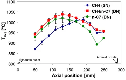
Fig. 3 shows a typical comparison among the furnace temperature profiles (averaged on the three radial thermocouple measurements) collected during the switch from clean MILD combustion conditions in the SN configuration using methane as a fuel to clean MILD combustion conditions in the DN configuration using n-heptane as a fuel with an air temperature pre-heating, Tpreheat, equal to 1050°C. It is possible to notice that the temperature profiles show a similar shape, even if in the SN methane MILD combustion the peak temperature (which is an indicator of the maximum fuel oxidation rate) is located closer to the burner nozzle tip (which is located at an axial distance equal to 290 mm), while the peak temperature moves towards the exhausts outlet in the DN n-heptane MILD combustion. This is coherent with both the different location of the fuel inlet (which is closest to the exhausts outlet in the DN configuration) as well as with the higher characteristic combustion time of the n-heptane droplets with respect to the gaseous methane. However, we can also see that in both the configurations the temperature profiles are quite flat (a maximum temperature difference of less than 150°C is evident from Fig. 3), as expected when MILD combustion conditions are achieved. Moreover, also an intermediate profile, measured when both methane from the bottom nozzle and
n-doi:10.1021/acs.iecr.9b02374
heptane from the lateral nozzle were fed to the burner, is reported in Fig. 3. As expected, this intermediate configuration shows a temperature profile close to that of the SN methane configuration near the bottom of the furnace (where the maximum methane combustion rate is located), while in the upper part of the furnace (where the maximum n-heptane combustion rate is located) it becomes closer to that of the DN n-heptane configuration. Also in this case the temperature profile is quite flat, clearly indicating that MILD combustion conditions are achieved also during the gradual transition from SN gaseous fuel to DN liquid fuel configuration.
Figure 3. Average temperature profiles measured during the firing procedure involving the switch
from the SN configuration with gaseous methane as a fuel to DN configuration with liquid n-heptane as a fuel (Tpreheat = 1050°C; overall fuel thermal input equal to 0.3 kW; KV = 7). Error bars indicate the maximum temperature deviations measured in the radial direction.
Similar conclusions arise from all the liquid fuels (both pure hydrocarbons and hydrocarbon-alcohol blends) investigated in this work, as shown for the sake of example in Fig. 4 for the two hydrocarbons (n-heptane and kerosene) both pure and blended (50% vol) with EtOH. In particular, Fig. 4a shows the NOx emissions measured during the switch from gaseous SN configuration (corresponding to the abscissa equal to 0) up to liquid DN configuration (corresponding to the abscissa equal to 100), while Fig. 4b shows the same trends for the average furnace temperature.
Exhausts outlet
doi:10.1021/acs.iecr.9b02374
All the hydrocarbons and hydrocarbons-alcohol blends investigated in this study evidenced a similar NOx trends when switching from SN gas to DN liquid configuration: NOx emissions slightly increases from methane MILD combustion to liquid MILD combustion, but they are always well below the clean MILD threshold of 30 ppm. As the system was always operated with the same overall fuel thermal input, the increased NOx formation should be probably ascribed to the Prompt-NOx mechanism52, which becomes more relevant for liquid fuels in the region where the droplets of the fuel spray evaporate leading to larger fuel/oxygen ratio values. However, clean MILD combustion conditions have been achieved not only with all the liquid fuels in the DN configuration, but also in all the intermediate configurations involved in the switch from the SN gas to the DN liquid configurations. This is also confirmed by the results shown by Fig. 4b, where no significant variations in the temperature trends are evidenced when switching from SN gas to the DN liquid configurations. Moreover, it is worth mentioning that the fuel conversion was always found to be complete, with no unburnt hydrocarbons and negligible CO emissions.
SN DN
doi:10.1021/acs.iecr.9b02374
Figure 4. NOx emissions at 3% O2 excess in the dry exhausts (a) and average furnace temperatures (b) as a function of the liquid to gaseous fuel ratio: 0% means SN gas configuration, while 100% means DN liquid configuration. Intermediate values indicates intermediate configurations achieved during the switch between SN gas and DN liquid configurations (Tpreheat=1000°C; overall fuel thermal input equal to 0.3 kW; KV = 7).
Coherently with previous results related to different liquid hydrocarbons34, the chemical nature of the liquid fuel seems to play a secondary role on the possibility of achieving MILD combustion conditions also when oxygenated fuels are involved. In other words, once the furnace enters MILD combustion conditions with a specific fuel (in this case methane), such conditions are maintained regardless the switch from one fuel to another one. This is supported also by the results reported in Fig. 5, where the NOx emissions measured in the DN configuration using different liquid fuels is reported as a function of the dilution ratio, KV. As expected, it is possible to see that decreasing the KV value leads to increase the NOx emissions until the clean MILD threshold limit of 30 ppm is exceeded. However, it is also clear that this happens for a KV value equal to about 2 regardless the fuel composition: this is a further confirmation that clean MILD combustion conditions are poorly affected by the fuel composition. Moreover, it can be noticed that while at high KV values the NOx emission profiles are quite flat, when decreasing the KV values they become quite sharp because the furnace is exiting quickly the MILD combustion conditions. This implies that the effect of small
SN DN
doi:10.1021/acs.iecr.9b02374
variations of the (arbitrary) NOx thresholds set to define the boundaries of the clean MILD combustion region on a Tavg vs. KV plane is quite negligible.
Figure 5. NOx emissions at 3% O2 excess in the dry exhausts (a) and average furnace temperatures (b) as a function of the dilution ratio, Kv, in the DN configuration (Tpreheat=1050°C; overall fuel thermal input equal to 0.4 kW).
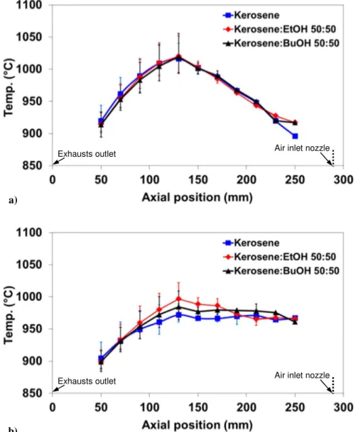
The negligible influence of the presence of alcohols in the liquid fuels is also evident from the results summarized in Fig. 6, which reports the temperature profiles measured along the furnace with two different exhaust recycle ratio in the DN configuration with some kerosene-alcohol blends. As can be seen, all the investigated fuels evidenced very similar trends, with low temperature differences both
a)
doi:10.1021/acs.iecr.9b02374
in the axial (lower than 120°C) and radial (lower than 60°C) directions, which clearly indicate that MILD combustion conditions are achieved.
Figure 6. Average thermal profiles obtained along the combustion chamber at Kv=7 (a) and Kv=4.5
(b) in the DN configuration (Tpreheat = 950°C; overall fuel thermal input equal to 0.4 kW). Error bars indicate the maximum temperature deviations measured in the radial direction.
3.2 Clean MILD combustion regions on the Tavg vs. KV plane
Several experiments have been carried out to identify clean MILD combustion regions on a Tavg vs. KV plane since these two parameters represent the main operating parameters influencing the
a)
b)
Exhausts outlet Air inlet nozzle
doi:10.1021/acs.iecr.9b02374
achievement of clean MILD combustion conditions. Fig. 7 summarizes the experimental results in terms of clean MILD combustion regions for some kerosene-based blends.
Figure 7. Experimental results for kerosene (a), kerosene:EtOH 50:50 vol. (b), kerosene:BuOH
50:50 vol. (c), and kerosene:AmOH 50:50 vol. (d). Dashed lines represent the clean MILD combustion region boundaries. Empty symbols represent experimental conditions fulfilling the clean MILD combustion requirements. Full squares and full triangles represent experimental conditions exceeding NOx and CO threshold limits, respectively.
The lower average furnace temperature boundary for the clean MILD combustion region, which is always identified by CO emissions larger than 50 ppm and corresponds to the beginning of the combustion extinction, is practically the same (equal to about 800°C) for all the investigated fuels. As previously discussed for the behavior of the NOx emission as a function of Kv, also in this case an increase of a few degrees of the average furnace temperature is enough to reduce the CO emissions close to zero, as shown in Fig. 8. This implies that also the effect of small variations of the
c) d)
doi:10.1021/acs.iecr.9b02374
(arbitrary) CO threshold selected to define the boundaries of the MILD combustion region on a Tavg vs. KV plane is quite negligible, being this threshold always at about 800°C.
On the contrary, the upper average furnace temperature boundary for the clean MILD combustion region increases almost linearly from Kv equal to about 1.5 up to Kv equal to about 4.5-5.5, where an almost constant value is reached. At higher Kv values the oxygen concentration is strongly reduced by the large exhausts recirculation and the NOx production is driven mainly by the furnace temperature.
In any case, as shown for the sake of example by the NOx emissions trends reported in Fig. 8, for liquid fuels the role of the Prompt-NOx route is quite relevant. As a matter of fact, at moderate temperature values the measured NOx concentrations are definitely too high to be explained by the Thermal-NOx route alone. In fact, while the Thermal-NOx formation rate is highly dependent on the temperature and only to a less extent on the oxygen concentration3, Prompt-NOx can be produced by nitrogen and hydrocarbon radicals in the fuel-rich regions at temperature values as low as 1500°C52.
Figure 8. CO and NOx emissions at 3% O2 excess in the dry exhausts as a function of the average furnace temperatures measured at different Kv for kerosene:BuOH 50:50 vol in the DN configuration.
It should be noted that a lower vertical boundary for the dilution ratio was arbitrarily imposed at Kv=1.5 since it was not always possible, due to the experimental limitations of the laboratory-scale
0 10 20 30 40 50 0 10 20 30 40 50 60 70 750 850 950 1050 1150 1250 1350 N O x ( p p m ) C O ( p p m ) Tavg(°C) CO @ Kv=3 CO @ Kv=5.5 NOx @ Kv=3 NOx @ Kv=5.5 NOx mild clean limit
doi:10.1021/acs.iecr.9b02374
burner, to characterize completely the combustion conditions in the low Kv region at the lower Tavg values.
Figure 9. Comparison among the clean MILD combustion boundaries determined for kerosene and
the 50:50 vol. kerosene-alcohol blends.
As summarized in Fig. 9, a comparison among the clean MILD combustion regions on the Tavg vs. KV plane for the kerosene-alcohol blends confirms that the location ad extension of the clean MILD regions are only marginally influenced by the chemical composition of the liquid fuel blends. A stable clean MILD combustion can be realized with alcohol fuel blends at temperatures slightly higher than those found for kerosene for Kv<5, where the upper limits of the alcohol-containing mixtures is about 60°C higher than that of kerosene. However, this difference is close enough to the experimental uncertainties to conclude that MILD combustion conditions can be sustained almost in the same region for both hydrocarbons and hydrocarbons-alcohol blends, in spite of their different physical and chemical properties. In other words, MILD combustion evidences a great flexibility for what concern the fuel properties, leading to the conclusion that it is possible to realize a clean MILD combustion also for alcohol-containing fuel blends.
4. Conclusions
750 850 950 1050 1150 1250 0.5 1.5 2.5 3.5 4.5 5.5 6.5 7.5 8.5T
a
v
g
(
°C
)
Kv
Kerosene Kerosene:EtOH Kerosene:BuOH Kerosene:AmOHdoi:10.1021/acs.iecr.9b02374
In this work the sustainability of MILD combustion conditions for liquid hydrocarbons containing oxygenated species has been investigated using a DN laboratory-scale burner. It has been found that injecting a liquid fuel spray into a high velocity jet of preheated air allows to sustain MILD combustion conditions for several different liquid hydrocarbons-alcohol blends once a MILD combustion environment has been previously attained using a gaseous fuel. Moreover, the MILD combustion region in the usual Tavg vs. Kv plane was found to be marginally influenced by the chemical composition of the liquid fuel blend. In particular, the possibility to sustain stable clean MILD combustion conditions also at low Kv values was evidenced. In these conditions, very low emissions of NOx and CO, as well as of unburnt hydrocarbons, were measured. Therefore, it was proposed that furnaces operating in the MILD combustion conditions are characterized by a great flexibility in terms of fuel properties, thus supporting the conclusion that a MILD combustion burner can create a suitable environment for several pollutant depression also when different oxygenated species are present in relevant quantities, such as in many fossil fuel – biofuel blends.
doi:10.1021/acs.iecr.9b02374
References
(1) Choi, G.M.; Katsuki, M. Chemical kinetic study on the reduction of nitric oxide in highly preheated air combustion. Proc. Combust. Inst. 2002, 29, 1165-1171.
(2) Cavaliere, A. ; de Joannon, M. Mild Combustion. Prog. Energy Combust. Sci. 2004, 30, 329-366.
(3) Cavigiolo, A.; Galbiati, M.A.; Effuggi, A.; Gelosa, D.; Rota, R. Mild combustion in a laboratory-scale apparatus. Combust. Sci. Technol. 2003, 175, 1347-1367.
(4) Derudi, M.; Villani, A.; Rota, R. Sustainability of mild combustion of hydrogen-containing hybrid fuels. Proc. Combust. Inst. 2007, 31, 3393-3400.
(5) Derudi, M.; Villani, A.; Rota, R. Mild Combustion of Industrial Hydrogen-Containing Byproducts. Ind. Eng. Chem. Res. 2007, 46, 6806-6811.
(6) Szego, G.G.; Dally, B.B.; Nathan, G.J. Operational characteristics of a parallel jet MILD combustion burner system. Combust. Flame 2009, 156, 429-438.
(7) Wünning, J.A.; Wünning, J.G. Flameless oxidation to reduce thermal NO-formation. Prog.
Energy Combust. Sci. 1997, 23, 81-94.
(8) Arghode, V.K.; Gupta, A.K. Effect of flow field for colorless distributed combustion (CDC for gas turbine combustion. Appl. Energy 2010, 87, 1631-1640.
(9) Perpignan, A.A.V.; Rao, A.G.; Roekaerts, D.J.E.M. Flameless combustion and its potential towards gas turbines. Prog. Energy Combust. Sci. 2018, 69, 28-62.
(10) Nemitallah, M.A.; Rashwan, S.S.; Mansir, I.B.; Abdelhafez, A.A.; Habib M.A. Review of Novel Combustion Techniques for Clean Power Production in Gas Turbines. Energy & Fuels
2018, 32, 979-1004.
(11) Effuggi, A.; Gelosa, D.; Derudi, M.; Rota, R. Mild Combustion of Methane-Derived Fuel Mixtures: Natural Gas and Biogas. Combust. Sci. Technol. 2008, 180, 481-493.
doi:10.1021/acs.iecr.9b02374
(12) Galletti, C.; Parente, A.; Derudi, M.; Rota, R.; Tognotti, L. Numerical and experimental analysis of NO emissions from a lab-scale burner fed with hydrogen-enriched fuels and operating in MILD combustion. Int. J. Hydr. Energy 2009, 34, 8339-8351.
(13) Ye, J.; Medwell, P.R.; Varea, E.; Kruse, S.; Dally, B.B.; Pitsch, H.G. An experimental study on MILD combustion of prevaporised liquid fuels. Applied Energy 2015, 151, 93-101.
(14) Katsuki, M.; Hasegawa, T. The science and technology of combustion in highly preheated air.
Proc. Combust. Inst. 1998, 27, 3135-3146.
(15) Mi, J.; Li, P.; Dally, B.B.; Craig, R.A.; Importance of initial momentum rate and air fuel premixing on moderate or intense low oxygen dilution (MILD combustion in a recuperative furnace. Energy & Fuels 2009, 23, 5349-5356.
(16) Plessing, T.; Peters, N.; Wünning, J.G. Laser optical investigation of highly preheated combustion with strong exhaust gas recirculation. Proc Combust Inst. 1998, 27, 3197-3204. (17) Arghode, V.K.; Gupta, A.K.; Bryden, M. High intensity colorless distributed combustion for
ultra low emissions and enhanced performance. Applied Energy 2012, 92, 822-830.
(18) Rebola, A.; Costa, M.; Coelho, P.J. Experimental evaluation of the performance of a flameless combustor. Appl. Therm. Eng. 2013, 50, 805-815.
(19) Colorado, A.F.; Herrera, B.A.; Amell, A.A. Performance of a flameless combustion furnace using biogas and natural gas. Bioresour. Technol. 2010, 101, 2443-2449.
(20) Tu, Y.; Su, K.; Liu, H.; Wang, Z.; Xie, Y.; Zheng, C.; Li, W. MILD combustion of natural gas using low preheating temperature air in an industrial furnace. Fuel Proc. Technol. 2017, 156, 72-81.
(21) Cheong, K.-P.; Wang, G.; Wang, B.; Zhu, R.; Rong, R.; Ren, W.; Mi, J. Stability and emission characteristics of nonpremixed MILD combustion from a parallel-jet burner in a cylindrical furnace. Energy 2019, 170, 1181-1190.
doi:10.1021/acs.iecr.9b02374
(22) Shu, Z.; Dai, C.; Li, P.; Mi, J. Nitric oxide of MILD combustion of a methane jet flame in hot oxidizer coflow: Its formations and emissions under H2O, CO2 and N2 dilutions. Fuel 2018, 234, 567-580.
(23) Cheong, K.-P.; Wang, G.; Mi, J.; Wang, B.; Zhu, R.R.; Ren, W. Premixed MILD Combustion of Propane in a Cylindrical Furnace with a Single Jet Burner: Combustion and Emission Characteristics. Energy & Fuels 2018, 32, 8817-8829.
(24) Mameri, A.; Tabet, F.; Hadef, A. MILD combustion of hydrogenated biogas under several operating conditions in an opposed jet configuration. Int. J. Hydrogen Energy 2018, 43, 3566-3576.
(25) Ozdemir, I.B. Peters, N. Characteristics of the reaction zone in a combustor operating at MILD combustion. Exp. Fluids 2001, 30, 683-695.
(26) Verissimo, A.S.; Rocha, A.M.A.; Costa, M. Importance of the inlet air velocity on the establishment of flameless combustion in a laboratory combustor. Exp. Therm. Fluid Sci. 2013,
44, 75-81.
(27) Verissimo, A.S.; Rocha, A.M.A.; Costa, M. Experimental study on the influence of the thermal input on the reaction zone under flameless oxidation conditions. Fuel Proc. Technol. 2013, 106, 423-428.
(28) Kruse, S.; Kerschgens, B.; Berger, L.; Varea, E.; Pitsch, H. Experimental and numerical study of MILD combustion for gas turbine applications. Appl. Energy 2015, 148, 456-465.
(29) Kumar, S.; Paul, P.J.; Mukunda, H.S. Investigations of the scaling criteria for a MILD combustion burner. Proc. Combust. Inst. 2005, 30, 2613–2621.
(30) Dally, B.B.; Riesmeier, E.; Peters, N. Effect of fuel mixture on moderate and intense low oxygen dilution combustion. Combust. Flame 2004, 137, 418-431.
(31) Xing, F.; Kumar, A.; Huang, Y.; Chan, S.; Ruan, C.; Gu, S.; Fan, X. Flameless combustion with liquid fuel: A review focusing on fundamentals and gas turbine application. Applied Energy
doi:10.1021/acs.iecr.9b02374
(32) Weber, R.; Smart, J.P.; Kamp, W. On the (MILD combustion of gaseous, liquid, and solid fuels in high temperature preheated air. Proc. Combust. Inst. 2005, 30, 2623-2629.
(33) Nada, Y.; Shibata, S.; Imaoka, M.; Kidoguchi, Y. Effect of the distance between fuel and oxidizer nozzles on NOx emissions from spray combustion furnaces incorporating high-temperature preheated oxidizers. J. Thermal Sci. Technol. 2015, 10, 1-14.
(34) Derudi, M.; Rota, R. Experimental study of the mild combustion of liquid hydrocarbons. Proc.
Combust. Inst. 2011, 33, 3325-3332.
(35) Reddy, V.M.; Sawant, D.; Trivedi, D.; Kumar, S. Studies on a liquid fuel based two stage flameless combustor. Proc. Combust. Inst. 2013, 34, 3319-3326.
(36) Reddy, V.M.; Katoch, A.; Roberts, W.L.; Kumar, S. Experimental and numerical analysis for high intensity swirl based ultra-low emission flameless combustor operating with liquid fuels.
Proc. Combust. Inst. 2015, 35, 3581-3589.
(37) Cui, Y.J.; Lin, Q.Z. Realization of Flameless Combustion of Liquid Fuel. Advanced Mater. Res.
2012, 512-515, 2088-2092.
(38) Sharma, S.; Pingulkar, H.; Chowdhury, A.; Kumar, S. A new emission reduction approach in MILD combustion through asymmetric fuel injection. Combust. Flame 2018, 193, 61-75.
(39) Sharma, S.; Kumar, R.; Chowdhury, A.; Yoon, Y.; Kumar, S. On the effect of spray parameters on CO and NOx emissions in a liquid fuel fired flameless combustor. Fuel 2017, 199, 229-238. (40) Li, P.; Wang, F.; Tu, Y.; Mei, Z.; Zhang, J.; Zheng, Y.; Liu, H.; Liu, Z.; Mi, J.; Zheng, C.
Moderate or Intense Low-Oxygen Dilution Oxy-combustion Characteristics of Light Oil and Pulverized Coal in a Pilot-Scale Furnace. Energy & Fuels 2014, 28, 1524-1535.
(41) Ye, J.; Medwell, P.R.; Evans, M.J.; Dally, B.B. Characteristics of turbulent n-heptane jet flames in a hot and diluted coflow. Combust. Flame 2017, 183, 330-342.
(42) Rodrigues, H.C.; Tummers, M.J.; van Veen, E.H.; Roekaerts, D.J.E.M. Effects of coflow temperature and composition on ethanol spray flames in hot-diluted coflow. Int. J. Heat Fluid
doi:10.1021/acs.iecr.9b02374
(43) Azevedo, C.G.; Andrade, J.C.; Souza Costa, F. Flameless compact combustion system for burning hydrous ethanol. Energy 2015, 89, 158-167.
(44) Ye, J.; Medwell, P.R.; Kleinheinz, K.; Evans, M.J.; Dally, B.B.; Pitsch, H.G. Structural differences of ethanol and DME jet flames in a hot diluted coflow. Combust. Flame 2018, 192, 473-494.
(45) Ye, J.; Medwell, P.R.; Dally, B.B.; Evans, M.J. The transition of ethanol flames from conventional to MILD combustion. Combust. Flame 2016, 171, 173-184.
(46) Agarwal, A.K. Biofuels (alcohols and biodiesel) applications as fuels for internal combustion engines. Progr. Energy Combust. Sci. 2007, 33, 233-271.
(47) Costa, C.R.; Sodré, R.J. Hydrous ethanol vs. gasoline-ethanol blend: engine performance and emissions. Fuel 2010, 89, 287-293.
(48) Balki, M.K.; Sayin, C. The effect of compression ratio on the performance, emissions and combustion of an SI (spark ignition) engine fueled with pure ethanol, methanol and unleaded gasoline. Energy 2014, 71, 194-201.
(49) Rakopoulos, D.C.; Rakopoulos, C.D.; Giakoumis, E.G.; Papagiannakis, R.G.; Kyritsis, D.C. Influence of properties of various common bio-fuels on the combustion and emission characteristics of high-speed DI (direct injection) diesel engine: vegetable oil, bio-diesel, ethanol, n-butanol, diethyl ether. Energy 2014, 73, 354-366.
(50) Al-Saraf, A.S.J.; Al-Jumaily, S.A.R. The power enhancement of a mini-gas turbine by adding ethanol to the compressor inlet air. Al-Khwarizmi Eng. J. 2013, 9, 54-64.
(51) Kerschgens, B.; Cai, L.; Pitsch, H.; Janssen, A.; Jakob, M.; Pischinger, S. Surrogate fuels for the simulation of diesel engine combustion of novel biofuels. Int. J. Engine Res. 2015, 16, 531-546. (52) Fenimore, C.P. Formation of nitric oxide in premixed hydrocarbon flames. Proc. Combust.
doi:10.1021/acs.iecr.9b02374