Autore:
Matteo Maria Andreozzi
Firma__________
Relatori:
Prof. Luciano Lenzini Firma__________
Ing. Giovanni Stea Firma__________
Performance Evaluation of LTE and LTE
advanced standards for next generation
mobile networks
Anno 2012
UNIVERSITÀ DI PISA
Scuola di Dottorato in Ingegneria “Leonardo da Vinci”
Corso di Dottorato di Ricerca in
Ingegneria dell’Informazione
1. ABSTRACT
The 3GPP standards LTE and LTE-Advanced for next generation mobile cellular networks are analysed.
The OptiMOS algorithm, which can be employed by the Base Station to efficiently serve VoIP connections, is described in Chapter [8].
The Relay Link scheduling algorithm, aimed to optimize LTE Advanced networks in presence of relay nodes is described in Chapter [9].
This work has been submitted in partial fulfilment of the requirements for
the Degree of Doctor of Philosophy in Information Engineering at the Information Engineering Department of the University of Pisa, Italy.
1. SOMMARIO
Nel corso della trattazione sono analizzati gli standard 3GPP LTE e LTE-Advanced per la prossima generazione delle reti mobili cellulari. L'algoritmo OptiMOS, che può essere impiegato dalla Stazione Base per servire in modo efficiente connessioni VoIP, è descritto nel capitolo [8].
L’algoritmo di link scheduling Relay, finalizzato a ottimizzare le reti LTE avanzate in presenza di nodi relay è descritto nel capitolo [9]. Questo lavoro è stato presentato in adempimento parziale dei requisiti per la Laurea di Dottore di Ricerca in Ingegneria dell'Informazione presso l'ufficio informazioni Dipartimento di Ingegneria dell'Università degli Studi di Pisa, Italia.
Index
1.
ABSTRACT
2
1.
SOMMARIO
3
2.
INTRODUCTION 6
3.
LTE TECHNOLOGY
12
4.
LTE ARCHITECTURE
15
4.1.1. E-UTRAN
PROTOCOL
STACK 20
4.1.2. U-P
LANE21
4.1.3. C-P
LANE27
5.
LTE CHANNELS MAPPING
29
5.1.1. L
AYER2
CHANNEL MAPPING29
5.1.2. L
AYER1
CHANNEL MAPPING33
6.
PHYSICAL LAYER
37
6.1.1. M
ULTIPATHF
ADING37
6.1.2. O
RTHOGONALF
REQUENCY-D
IVISIONM
ULTIPLEXING40
6.1.3. O
RTHOGONALF
REQUENCY-D
IVISIONM
ULTIPLEA
CCESS45
6.1.4. S
INGLEC
ARRIER–
F
REQUENCYD
IVISIONM
ULTIPLEA
CCESS46
6.1.5. LTE
DOWNLINK MULTIPLEXING SCHEME49
6.1.6. LTE
UPLINK MULTIPLEXING SCHEME53
6.1.7. MIMO 54
6.1.8. MIMO
CONFIGURATIONS55
6.1.9. D
IVERSITY56
6.1.10. S
PATIAL MULTIPLEXING58
6.1.11. B
EAM FORMING59
7.
LTE ADVANCED 60
7.1.1. R
ELAY SUPPORT FORLTE-A
DVANCED61
7.1.2. R
ELAYN
ODES62
7.1.3. D
ISTRIBUTED ANTENNA SYSTEM64
8.
LTE AND LTE ADVANCED ALGORITHMS FOR RESOURCE SCHEDULING
66
8.1.1. O
PTIMAL PAY-
OUT BUFFER SIMULATOR70
8.1.3. P
ERFORMANCEE
VALUATION76
9.
A LINK SCHEDULING ALGORITH FOR LTE-ADVANCED NETWORKS 81
9.1.1. R
ELAYD
UPLEXINGP
ROBLEM81
9.1.2. A
LGORITHM OBJECTIVE82
9.1.3. F
EEDBACK ASSUMPTIONS83
9.1.4. L
INK-
SCHEDULING-
PROBLEM FORMULATION83
9.1.5. A
NALYTICAL FORMULATION84
9.1.6. I
DEALIZATIONS86
9.1.7. P
ROPOSEDA
LGORITHM87
9.1.8. A
CCESSS
TEP87
9.1.9. A
CCESSC
APACITYC
OMPUTATIONA
LGORITHM88
9.1.10. B
ACKHAULS
TEP88
9.1.11. B
ACKHAUL CAPACITIES COMPUTATION ALGORITHM89
9.1.12. P
ERFORMANCEE
VALUATION91
9.1.13. T
RAFFIC TYPES92
9.1.14. R
ELAYS
IMULATIONS SETTINGS93
9.1.15. S
IMULATIONR
ESULTS95
10.
CONCLUSIONS 96
2. INTRODUCTION
Yeah, you'll be the coolest person in the room when you pull one out and show it around, but that gets old fast when three other people have them and one person somehow has one that glows in the dark. John C. Dvorak
The American columnist and broadcaster in article 'Rethinking the iPhone' in PC Magazine.
The early days of mobile telephony started in 1946 in St. Louis, where the Mobile Telephone Service was first introduced. Call set-up required manual operation by an operator and there were only three radio channels available for use, therefore the service was limited by having only a few voice channels per district.
In 1964 additional channels were added to the service (IMTS) and handling of calls to the public switched telephone network (PSTN) was more automated.
Later on, other technologies were introduced in so-called pre-cellular systems (or zero G), such as the Push to Talk (PTT) and Advanced Mobile Telephone System (AMTS).
These early mobile telephone systems could be only distinguished from closed radiotelephone systems in that they were available as a commercial service that was part of PSTN, with their own telephone numbers, rather than part of a closed network such as a police radio or taxi dispatch system.
Even tough this early services became very popular and commercial useful, they were limited to that phones could only be installed in cars and other vehicles.
It was April 3, 1973. Martin Cooper, now CEO and co-founder of ArrayCom Inc, was Motorola general manager of Communication Systems division.
He made that call. He called Cooper, his rival at AT&T Bell Labs from the streets of New York City, and the world of communications made a giant leap forward towards the nowadays worldwide interconnected network of mobile nodes.
The handheld telephony was born.
The first commercial first generation network (1G) was launched by NTT in Japan, in 1979. There were 23 radio sites (base stations) covering the whole Tokyo area, serving more than 20 million people, and base stations already supported the hand-over between sites, i.e. the ability to transfer calls between one radio site and another.
Five years later, NTT became the first operator in the World to cover a whole nation with a mobile cellular network.
In the early 80s many other nations saw the mobile communications dawn with the implementation of nation-wide 1G networks: UK, Canada, Mexico were the first ones.
Among the first international mobile communication systems started in the early 1980s, the best-known ones were NMT that was started up in the Nordic countries, AMPS in the USA, TACS in Europe, and J-TACS in Japan.
Equipment was still bulky, mainly car-borne, and voice quality was often inconsistent, with “cross-talk” between users being a common problem.
With NMT came the concept of “roaming”, providing a service for users traveling outside the area of their “home” operator.
This opened a larger market for mobile phones, attracting more companies into the mobile-communication business.
Mobile technology evolved rapidly, and in early 90s the second generation of mobile cellular networks came to life (GSM or 2G).
In Europe, the GSM (originally Groupe Spécial Mobile, later Global System for Mobile communications) was deployed, based on a project for pan-European mobile-telephony system, which was initiated in the mid 1980s by the telecommunication administrations in CEPT1 and later continued within the new European Telecommunication Standards Institute (ETSI).
The GSM standard was based on Time-Division Multiple Access (TDMA), as were the US-TDMA standard and the Japanese PDC standard that were introduced in the same time frame.
Some years later development of a Code-Division Multiple Access (CDMA) standard called IS-95 was completed in the USA in 1993.
It was the first full digital mobile cellular technology, which featured also out-of-band signaling and – most important thing – introduced the short messaging service (SMS), which had a great success among customers, and is still supported by current cellular mobile technologies. Along with that, circuit-switched data services were also introduced, enabling e-mail access and other narrowband data applications, at initial peak data rate of 9.6 kbit/s. Higher data rates were introduced later in evolved 2G systems by assigning multiple time slots to a user and through modified coding schemes.
Later on, in 1999, Docomo, Japan, was introducing mobile Internet access service for the first time in the history, with the Japanese PDC standard.
General Packet Radio Services (GPRS) was introduced at the same time in GSM for supporting packet data transmission.
These technologies are often referred to as 2.5G.
Starting from 2000, daily use of mobile phones became a worldwide fact, and demand for evolved services, such as Internet access, incessantly grew.
Along with that, users also were demanding for always-higher data speeds, having experienced the same kind of evolution with respect to fixed broadband access technology.
However, during same years, having the 2G technologies clearly reached its limits, the mobile operators and devices industry players begun to work on the third generation (3G) technology. With the advent of 3G and the higher-bandwidth radio interface of UTRA (Universal Terrestrial Radio Access) came possibilities for a range of new services that were only hinted at with 2G and 2.5G.
The 3GPP – The Third Generation Partnership Project – was established in 1998, as a collaboration among international groups of telecommunication associations, aiming to define globally applicable standards for next generation mobile networks.
Figure 1 - The 3GPP consortium
As a result of the 3GPP consortium, the 3G standard was defined (commercially known as UMTS), merging the winning WCDMA (Wideband CDMA) concepts from a European research project (FRAMES) and from the ARIB standardization in Japan.
Before 3GPP, standardization of WCDMA was continuing in parallel among several standards groups. This solved the problem of trying to maintain parallel development of aligned specifications in multiple regions.
Japan
The present organizational partners of 3GPP are ARIB (Japan), CCSA (China), ETSI (Europe), ATIS (USA), TTA (South Korea), and TTC (Japan).
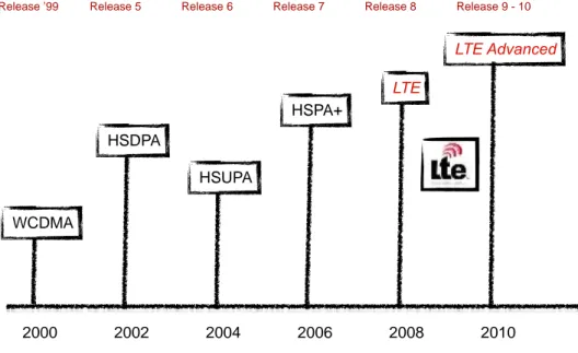
The first release of WCDMA Radio Access was called release 99. This release was characterized by circuit-switched voice and video services, and data services over both packet-switched and circuit switched bearers. The first major addition of radio access features to WCDMA was HSPA, which was added in release 5 with High Speed Downlink Packet Access (HSDPA) and release 6 with High Speed Uplink Packet Access (HSUPA). These two are together referred to as HSPA.
HSPA introduced new basic functions and was aimed to achieve peak data rates of 14.0 Mbit/s. The main introduced technologies within the HSPA were the adaptive modulation QPSK and 16QAM and the High Speed Medium Access protocol (MAC-hs) in base station, which enabled it to fast scheduling execution.
Soon after the second phase of HSPA was specified in the 3GPP release 7, named HSPA Evolved. It was designed to achieve data rates of up to 42 Mbit/s, by introducing multiple antenna techniques (MIMO and Beam-Forming).
In last years, however, the number of mobile subscribers has increased tremendously and voice communication has become mobile in a massive way. At the same time data usage has grown fast and mobile devices are now used for a wide range of other applications like web browsing, video streaming and online gaming. Beside smart phones, also notebooks, tablets and other hand-held devices are now part of the mobile environment, leading to a heterogeneous population of User Equipment (UEs) with different needs.
Within such a scenario, the demand for an ubiquitous and wide-band Internet access is constantly increasing, and mobile communication systems have to provide evolved technologies to improve support for bandwidth intensive and delay sensitive applications.
As direct evolution of HSPA Evolved, the 3GPP roadmap leaded to E-UTRA (Evolved Universal Terrestrial Radio Access), the technology specified in 3GPP Release 8.
This project is called the Long Term Evolution initiative (LTE). The first release of LTE offers data rates of over 320 Mbit/s for downlink and over 170 Mbit/s for uplink using OFDMA modulation.
Figure 2 - 3GPP releases 2000 2002 2004 2006 2008 2010 Release ’99 WCDMA HSDPA HSUPA HSPA+ LTE LTE Advanced
3. LTE TECHNOLOGY
Long Term Evolution (LTE) is a service-optimized 4th-generation cellular technology, aiming to speed improvements up to 10-fold over existing 3G technologies was planned starting from 2004, when a workshop was organized to initiate work on the 3GPP Long-Term Evolution (LTE) radio interface.
The result of the LTE workshop was that a study item in 3GPP TSG RAN1 was created in December 2004. The first 6 months were spent on defining the requirements, or design targets, for LTE, which were approved in June 2005.
Most notable were the requirements on high data rate at the cell edge and the importance of low delay, in addition to the normal capacity and peak data rate requirements.
Furthermore, spectrum flexibility and maximum commonality between FDD and TDD solutions were pronounced.
Being able to support the same Internet Protocol (IP)-based services in mobile devices that people use at home with a fixed broadband connection was a major challenge and a prime driver for the evolution of LTE, thus one of the main ways in which 4G differed technologically from 3G was in its elimination of circuit switching, instead employing an all-IP network.
4G ushered in a treatment of voice calls just like any other type of streaming audio media, utilizing packet switching over Internet, LAN or WAN networks via VoIP.
1
TSG Radio Access Network (TSG RAN) is responsible for the definition of the functions, requirements and interfaces of the UTRA/E-UTRA network in its two modes, FDD & TDD. More precisely: radio performance, physical layer, layer 2 and layer 3 RR specification in UTRAN/E-UTRAN; specification of the access network interfaces (Iu, Iub, Iur, S1 and X2); definition of the O&M requirements in UTRAN/E-UTRAN and conformance testing for User Equipment and Base Stations.
LTE has been designed also in order to ensure the competitiveness of 3GPP technologies for the next years.
These improvements rely on some enabling technologies which were not considered in the previous releases of the UMTS technologies, i.e. the adoption of Orthogonal Frequency Division Multiple Access (OFDMA) and Single Carrier Orthogonal Frequency Division Multiple Access (SC-OFDMA) as downlink and uplink access scheme are an essential part of the LTE standard, as well as the inclusion of complex Multiple Input Multiple Output (MIMO) antenna schemes.
The major improvements LTE accomplished with respect to previous 3GPP releases are:
– Data rate: theoretical achievable peak data rate (measured at physical layer) of 300 Mbps in downlink and 75 Mbps in uplink, given the standard configuration of full spectrum (20 MHz) bandwidth.
– Spectrum flexibility: spectrum bandwidth scalable from 1.25 up to 20 MHz in order to support different deployment requirements.
– Architecture simplification: the number of elements composing the UMTS Terrestrial Radio Access Network (UTRAN) structure has been reduced, converging towards a flat architecture.
– Enhanced support for mobility:
– System performances optimized for slow-moving users (0 - 15 km/h) – High performances still achieved for users moving at speeds between 15 -
150 km/h
– Minimum quality of experienced services still guaranteed at very high speed (up to 350 km/h).
– Reduced latency: the one-way transit time between a packet being available at the IP layer in either the UE or radio access network and the availability of this packet on the counterpart shall be 5ms in normal operating conditions. Also Control Plane latency is reduced, being attested at less than 100ms.
– Enhanced support for end-to-end Quality of Service (QoS): an all-IP paradigm is used to deal with different traffic flows. Voice traffic is served as VoIP (Voice over IP) and the call quality should be at least the same as in UMTS circuit switched networks, measured as ITU-MOS score ([17],[18]).
Figure 3 - LTE will fully support VoIP technology with the highest QoS w.r.t. current technologies
– Inter-working: inter-working with existing legacy 3GPP systems and non-3GPP systems is ensured, with handover added delay time between 300 and 500ms.
Figure 4 - LTE data rate improvement
0 25000,0 50000,0 75000,0 100000,0 GPRS EDGE WCDMA HSPA HSPA+ LTE
4. LTE ARCHITECTURE
The LTE has been designed to be a full packet-switched services technology (thus dropping circuit-switched services of the previous cellular generations).
Full IP connectivity is provided between the UE and the Packet Data Network (PDN).
Four high-level logical domains compose the LTE network architecture [Figure 5]:
• Services domain
• EPC (Evolved Packet Core)
• E-UTRAN (Evolved UMTS Terrestrial Radio Access Network) • User Equipment domain
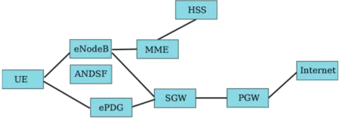
The Evolved Packet Core (EPC) is a part of the so-called System Architecture Evolution (SAE), which comprehends all the non-radio access part of the LTE system (opposed to the E-UTRAN level). EPC is shown in detail in Figure 6.
Figure 6 - Evolved Packet Core
The EPC evolves from previous core network structure showing a full separation of Control Plane and User Plane functionalities, embodied by two different network components: the Mobility Management Entity (MME) and the Serving Gateway (SGW) respectively. These two entities communicate using the S11 interface as shown in the above picture. Full domain separation provides the system with a dedicated node (S-GW) for high bandwidth packet processing and a control node (MME), which is responsible of all signalling transactions.
The MME is responsible for idle mode UE tracking and paging procedure including retransmissions. It is involved in the bearer activation/deactivation process and is also responsible for choosing the SGW for a UE at the initial attach and at time of intra-LTE handover involving Core Network node relocation. It is responsible for authenticating the user. The Non Access Stratum (NAS) signalling terminates at the MME and it is also responsible for generation and allocation of temporary identities to UEs. It checks the authorization of the UE to camp on the service provider’s Public Land Mobile Network (PLMN) and enforces UE roaming restrictions. The MME is the termination point in the network for ciphering/integrity protection for NAS signalling and handles the security key management. Lawful interception of signalling is also supported by the MME. The MME finally provides
the control plane function for mobility between LTE and 2G/3G access networks with the S3 interface terminating at the MME from the SGSN. Here follows a list of all MME features:
Idle mode UE tracking and paging procedure including retransmissions;
Bearer activation/deactivation process;
SGW selection at the initial attach and at time of intra-LTE handover;
Mobility between LTE and 2G/3G access networks;
UE authentication;
Generation and allocation of temporary identities to UEs;
Authorization checks of the UE to camp on the service provider’s PLMN;
UE roaming restrictions enforcing.
Ciphering and integrity protection for NAS signalling and security key management;
Lawful interception.
The SGW routes and forwards user data packets, while also acting as the mobility anchor for the user plane during inter-eNodeB handovers and as the anchor for mobility between LTE and other 3GPP technologies (terminating S4 interface and relaying the traffic between 2G/3G systems and PDN Gateway - PGW). For idle state UEs, the SGW terminates the downlink data path and triggers paging when downlink data arrives for the UE. It manages and stores UE contexts, e.g. parameters of the IP bearer service, network internal routing information. It also performs replication of the user traffic in case of lawful interception.
Its main functions are listed below:
The anchor role for inter-eNodeB handovers and for inter-3GPP mobility;
Routing and forwarding of user data packets;
Traffic relaying among PGWs;
Downlink packets buffering;
Paging triggering upon UE downlink data arrival;
Handling UE context (e.g. parameters of the IP bearer service, network internal routing information, etc.)
Downlink packet marking (e.g. by marking DiffServ field in IP packets making use of QCI field).
The PDN Gateway (PGW) is also part of the EPC and provides connectivity from the UE to external packet data networks by being the point of exit and entry of traffic for the UE. A UE may have simultaneous connectivity with more than one PGW for accessing multiple Packet Data Networks (PDNs). The PGW performs policy enforcement, packet filtering for each user, charging support, lawful interception and packet screening. Another key role of the PGW is to act as the anchor for mobility between 3GPP and non-3GPP technologies such as WiMAX and 3GPP2 (CDMA 1X and EvDO). Its features, detailed point by point, are:
The anchor role for mobility between 3GPP and non-3GPP technologies such as WiMAX and 3GPP2 (CDMA 1X EvDO);
Policy enforcement;
Packet filtering for each user;
Charging support;
Lawful interception;
Packet screening.
Other three nodes complete the EPC structure, each one providing specific control functions:
1. HSS (Home Subscriber Server): The HSS is a central database that contains
user-related and subscription-related information. The functions of the HSS
include functionalities such as mobility management, call and session
establishment support, user authentication and access authorization. The HSS
is based on pre-Release-4 Home Location Register (HLR) and Authentication
Centre (AuC).
2. ANDSF (Access Network Discovery and Selection Function): The ANDSF
provides information to the UE about connectivity to 3GPP and non-3GPP
access networks (such as Wi-Fi). The purpose of the ANDSF is to assist the UE
to discover the access networks in their vicinity and to provide rules (policies)
to prioritize and manage connections to these networks.
3. EPDG (Evolved Packet Data Gateway): The main function of the ePDG is to
secure the data transmission with a UE connected to the EPC over an
untrusted non-3GPP access. For this purpose, the ePDG acts as a termination
node of IPSec tunnels established with the UE.
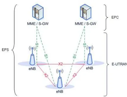
The EPC and E UTRAN together form the Evolved Packet System (EPS), shown in [Figure 7]
The E-UTRAN is the radio access network of LTE (air interface) and consists of eNodeB, which are an evolution of the UTRAN NodeB, which are interconnected by X2 interfaces.
An eNodeB provides the U-Plane (PDCP/RLC/MAC/PHY) and C-Plane (RRC) and acts as termination towards the UE.
The eNodeB is responsible for Radio Resource Management (RRM), i.e. it controls and coordinates the Radio Bearer Control (RBC), Radio Admission Control (RAC), Connection Mobility Control (CMC), and dynamic allocation of resources to UEs in uplink and downlink directions.
The eNodeB is also the node responsible of establishing C-Plane connectivity towards a specific MME (MME selection function), and of routing of U-Plane data towards SGW.
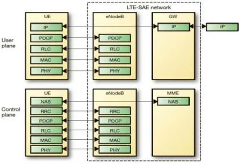
4.1.1. E-UTRAN PROTOCOL STACK
In figure [Figure 8] are shown the protocol stacks of U-Plane and C-Plane.
4.1.2. U-Plane
The protocol stack for the U-Plane consists of:
Packet Data Convergence Protocol (PDCP): provides transport of the IP packets, with ROHC header compression, ciphering, and depending on the RLC mode in-sequence delivery, duplicate detection and retransmission of its own SDUs during handover. Its features are:
Header compression and decompression (i.e. ROHC2);
Transfer of user data;
In-sequence delivery of upper layer PDUs (i.e. IP datagrams);
Duplicate detection of lower layer SDUs (i.e. RLC SDUs);
Retransmission of PDCP SDUs at handover;
Ciphering and deciphering;
Timer-based SDUs discarding in uplink.
[Figure 9] represents the PDCP PDU Structure.
PDCP SDU
PDCP header
PDCP PDU
Figure 9 - PDCP PDU 2When header is as big as the data being transmitted, it generates overhead wasting the precious air resource. For that, header compression is generally performed. A compressor is used before the data is sent and a de-compressor at the receiving end adds the uncompressed headers back to the received packets. Both the ends must use the same protocol (i.e. ROHC).
PDCP header can be either 1 or 2 bytes long and both PDCP PDU and PDCP header are octet-aligned.
Radio Link Control (RLC): it transports the PDCP's PDUs. It can work in 3 different modes depending on the reliability provided: RLC Acknowledged Mode, Unacknowledged Mode, and Transparent Mode. Depending on this mode it can provide: ARQ error correction (AM only), segmentation/concatenation of PDUs, reordering for in-sequence delivery, duplicate detection (AM and UM). Its functions are, in detail:
Transfer of upper layer PDUs (i.e. PDCP PDUs);
Error correction through ARQ3 (for AM data transfer);
Concatenation, segmentation and reassembly of RLC SDUs (for both UM and AM data transfer);
Re-segmentation of RLC data PDUs for AM data transfer;
In-sequence delivery of upper layer PDUs (i.e. PDCP PDUs) (for both UM and AM data transfer);
Duplicate detection (for both UM and AM data transfer);
Protocol error detection and recovery;
RLC SDUs discarding (for both UM and AM data transfer);
RLC re-establishment.
[Figure 10] shows the RLC PDU Structure.
3
The ARQ functionality provides error correction by implementing a retransmission
protocol in RLC AM at layer 2. Reception of a negative RLC status message will trigger a retransmission of the corresponding RLC PDU(s).RLC header RLC PDU ... ... n n+1 n+2 n+3 RLC SDU RLC header Figure 10 - RLC PDU
Red lines indicate the occurrence of segmentation. Segmentation only occurs when needed and concatenation is done in sequence. PDU sequence number carried by the RLC header is independent of the SDU sequence number (i.e. PDCP sequence number).
Media Access Control (MAC): the MAC layer offers to the RLC layer a set of logical channels, which are multiplexed in physical layer transport channels. It manages the HARQ error correction, handles the prioritization of the logical channels for the same UE and the dynamic scheduling between UEs.
Its main roles are:
Channel mapping (between logical channels and transport channels);
Multiplexing/de-multiplexing of MAC SDUs (belonging to one or different logical channels into/from transport channels);
Delivering of TBs4 to/from the PHY layer (on transport channels);
Scheduling information reporting;
Error correction through HARQ5;
4
Each MAC PDU is mapped 1 to 1 onto physical transport block (TB). 5
The HARQ functionality ensures delivery between peer entities at layer 1. It is an N-channel stop-and-wait protocol with asynchronous downlink retransmissions and synchronous uplink retransmissions. If RLC AM is enabled, the two-layer ARQ design (ARQ+HARQ) achieves low latency and low overhead without sacrificing reliability. Most of the errors are however captured and corrected by the HARQ
Priority handling (between logical channels of one UE);
Dynamic scheduling;
MBMS service identification;
Transport format selection;
Padding.
All data flowing to and from the MAC layer are structured in MAC Packet Data Units (PDU). Figure 11 illustrates the MAC PDU Structure.
Figure 11 - MAC PDU A MAC PDU consists of:
MAC header. It is composed of one or more MAC PDU sub-headers; each sub-header refers to a MAC Service Data Unit (SDU), a MAC Control Element (CE) or indicates presence of padding. MAC header has therefore a variable size.
MAC CEs. There are different kinds of MAC CEs:
o Buffer Status Report (BSR). BSR are used by UEs to advertise their transmission buffer sizes.
o C-RNTI. As the C-RNTI may be used on common transport channels for optimization purposes, this MAC CE is used to specify it.
o DRX Command. As UEs enter IDLE mode when there is no activity, they use DRX in IDLE mode in order to wake up periodically and check for paging messages.
protocol and only residual errors are detected and resolved by the more expensive (in terms of latency and overhead) ARQ retransmissions.
o UE Contention Resolution Identity. Contention Resolution procedure is based on either C-RNTI on PDCCH or UE Contention Resolution Identity on DL-SCH. In order to specify the UE Contention Resolution Identity this MAC CE is used. o Timing Advance Command. This MAC CE specify a value
used to control the amount of timing adjustment that UE has to apply in order to adjust its uplink transmission timing for PUCCH/PUSCH/SRS.
MAC SDUs: MAC SDUs are always placed after any MAC CE and have variable sizes.
Optional padding. Data that UE ignores used for formatting the PDU in precise standardized size formats (TBS – Transport Block Size).
Physical layer (PHY): PHY offers data transport services to higher layers. Carries all information from the MAC transport channels over the air interface. Takes care of the link adaptation (AMC), power control, cell search (for initial synchronization and handover purposes) and other measurements (inside the LTE system and between systems) for the RRC layer. The access to these services is through the use of “transport channels” via the MAC sub-layer. It performs:
Error detection (on the transport channel and indication to higher layers);
FEC encoding/decoding (of the transport channel);
HARQ soft-combining;
Rate matching (of the coded transport channel to physical channels);
Channel mapping (mapping of coded transport channel onto physical channels);
Power weighting (of physical channels);
Modulation and demodulation (of physical channels);
Frequency and time synchronization;
Radio characteristics measurements (and indication to higher layers);
Transmit Diversity;
Beam-forming;
RF processing.
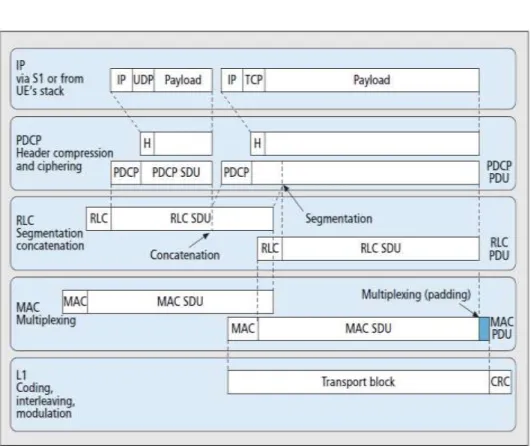
Figure 12 - Data flow for U-Plane protocol stack
PHY layer packets are the Transport Blocks (TB). A maximum of one MAC PDU can be transmitted per TB per UE6. Figure 12] shows the data flow through the whole U-Plane protocol stack.
6
In both uplink and downlink, only one TB is generally created in a TTI. However,
up to 2 TBs may be generated in a TTI if MIMO is enabled.4.1.3. C-Plane
The protocol stack for the C-Plane consists of:
PDCP. For the RRC layer it provides transport of control plane and performs ciphering and integrity protection.
RLC, MAC and PHY. These layers are responsible for providing transport support of RRC control data.
Radio Resource Control (RRC). It takes care of: the broadcasted system information related to the access stratum and transport of the non-access stratum (NAS) messages, paging, establishment and release of the RRC connection, security key management, handover, UE measurements related to inter-system (inter-RAT) mobibility, QoS establishment. Its features are listed below:
o Broadcast of system information related to the NAS and AS; o Paging;
o Establishment, maintenance and release of an RRC connection between the UE and E-UTRAN including allocation of temporary identifiers between UE and E-UTRAN and configuration of signaling radio bearers for RRC connection; o Security functions including key management;
o Establishment, configuration, maintenance and release of point-to-point Radio Bearers;
o Mobility functions including UE measurement reporting and control of the reporting for inter-cell and inter-RAT mobility, handover, UE cell selection and reselection and control of cell selection and reselection, context transfer at handover;
o Notification for MBMS services;
o Establishment, configuration, maintenance and release of RBs for MBMS services;
o QoS management functions;
o NAS direct message transfer to/from NAS from/to UE.
Non-Access Stratum (NAS). NAS performs additional control functions:
o EPS bearer management; o Authentication;
o Mobility handling; o Paging origination; o Security control.
RRC and NAS layers top each UE C-Plane. All NAS control messages are exchanged between UE and MME: eNB silently hands over all NAS messages to MME.
5. LTE CHANNELS MAPPING
5.1.1. Layer 2 channel mapping
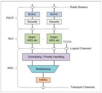
Layer 2 is split into previously discussed PDCP, RLC and MAC layers. Figure 13 illustrates the downlink structure of layer 2, while Figure 14 shows the uplink one.
Figure 13 - Downlink Layer 2 structure
SAPs are marked with circles at the interface between sub-layers:
SAPs between the PDCP sub-layer and the upper layer offer connection to the radio bearers;
SAPs between the MAC sub-layer and the RLC sub-layer are the connection point for logical channels;
SAPs between the physical layer and the MAC sub-layer are dedicated to transport channels.
Radio Bearers (RBs) are logical channel over the radio interface and are established using RRC protocol. There are two main types of radio bearers:
Signalling Radio Bearer (SRB). SRBs are defined as RBs dedicated to transmission of RRC and NAS messages.
Data Radio Bearer (DRB). The DRBs are used to carry user data (i.e. IP datagrams). Each DRB is associated with an EPS Bearer7.
Part of the bearer establishment procedure is authentication and activation of encryption. The required data for this process is retrieved by the eNodeB from the MME. The MME also delivers all necessary information that is required to configure the data radio bearer, like minimum and maximum required bandwidth, maximum tolerable delay and other QoS parameters.
MAC layer offers different service modes for data transfer. Each logical channel type defines the type of information transferred on it. A general classification of logical channels is listed below:
Control channels. Control channels are employed for transferring C-Plane information only. Control channels available at MAC layer are:
7
Each EPS Bearer is associated with a Traffic Flow Template (TFT). A TFT is a
set of packet filters. Packet filtering uses IP header information like source address, destination address, ToS field, TCP port, etc. Because of that each TFT is mapped on a given QoS and all the data that mapped to this TFT receives the same QoS treatment.o Broadcast Control Channel (BCCH), a downlink channel used to transmit broadcast system control information;
o Paging Control Channel (PCCH), a downlink channel used to transmit paging information and system information change notifications
o Common Control Channel (CCCH), a channel used to transmit control information between UEs and network (used for UEs having no RRC connection with the network – RRC idle mode);
o Multicast Control Channel (MCCH), a point-to-multipoint downlink channel used to transmit MBMS control information from the network to the UE, for one or several MTCHs (this channel is only used by UEs that receive MBMS);
o Dedicated Control Channel (DCCH), a point-to-point bi-directional channel that transmits dedicated control information between a UE and the network (this channel is used by UEs having an RRC connection – RRC connected mode).
Traffic channels. Traffic channels are dedicated to transmission of U-Plane information. Traffic channels available at MAC layer are:
o Dedicated Traffic Channel (DTCH), point-to-point channel, dedicated to single UE, for transmission of user information (a DTCH can exist in both uplink and downlink).
o Multicast Traffic Channel (MTCH), a point-to-multipoint downlink channel carrying data from the network to the UE (this channel is only used by UEs that receive MBMS).
MAC layer is transparent for BCCH, CCCH and PCCH (i.e. it forwards their content without any processing).
In order reduce complexity of LTE protocol architecture; the number of transport channels has been reduced with respect to previous 3GPP releases. Transport channels abstract at PHY layer different kinds of data transfer services: each
transport channel type defines the type of information transferred on it. Downlink transport channels are:
Broadcast Channel (BCH);
Multicast Channel (MCH);
Downlink Shared Channel (DL-SCH);
Paging Channel (PCH). Uplink transport channels are:
Uplink Shared Channel (UL-SCH);
Random Access Channel (RACH).
Radio bearers are mapped 1 to 1 on logical channels, while logical channels are mapped on transport channels following the rules shown in [Figure 15] and [Figure 16].
Figure 16 - Uplink logical channels to transport channels mapping
5.1.2. Layer 1 channel mapping
PHY layer provides as well channels enabling different data services to be transferred on separated channels. Transport channels are mapped on physical channels by PHY layer, which carry information originating from higher layers (i.e. MAC layer). A physical layer is identified also by a specific set of Resource Elements (REs)8. Downlink physical channels are:
Physical Downlink Shared Channel (PDSCH). PDSCH purpose is enabling user data transport. It has been designed in order to deliver very high data rates, by supporting all LTE available modulations - QPSK, 16QAM and 64QAM.
Physical Broadcast Channel (PBCH). PBCH carries system information for accessing the network. Only QPSK modulation is available on this channel.
Physical Multicast Channel (PMCH). PMCH carries system information for multicast. Uses QPSK modulation.
8
A Resource Element (RE) is a unit of allocation in the time and frequency domains. One RE corresponds to one subcarrier on frequency domain and one OFDM symbol on time domain.
Physical Downlink Control Channel (PDCCH). PDCCH conveys UE-specific control information (e.g. scheduling information). Encodes its data by using QPSK modulation only.
Physical HARQ Indicator Channel (PHICH). PHICH is dedicated to HARQ signalling.
Physical Control Format Indicator Channel (PCFICH). PCFICH carry required information for decoding PDSCH.
Uplink physical channels are:
Physical Uplink Shared Channel (PUSCH). PUSCH is used for unicast transmission and paging. QPSK, 16QAM or 64QAM modulations are available.
Physical Uplink Control Channel (PUCCH). PUCCH carries uplink control information. It is never transmitted simultaneously with PUSCH data. PUCCH conveys control information about channel quality, HARQ ACKs and NACKs, uplink-scheduling requests.
Physical Random Access Channel (PRACH). PRACH is used for random access procedures9.
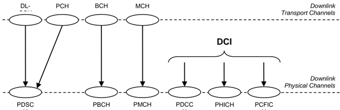
Transport channels are mapped on physical channels following the rules shown in figures [Figure 16] and [Figure 17].
9
Random access is the process by which a terminal requests a connection setup.
BCH DL-SCH PCH MCH PDSC H PBCH PMCH PDCC H PHICH PCFIC H DCI Downlink Physical Channels Downlink Transport Channels
Channels marked in the figure as DCI are responsible for carrying downlink control information. Such information are HARQ feedback, scheduling grants for resource assignment (supporting dynamic scheduling), modulation and coding scheme indications, power control commands, feedback reporting requests.
Some uplink physical channels as well are enabled to transmit Uplink Control Information (UCI). This information consist of HARQ feedback, scheduling requests, feedback reports.
UL-SCH RACH PUSC H PRAC H PUCC H UCI Uplink Physical Channels Uplink Transport Channels
6. PHYSICAL LAYER
Cellular systems previous to LTE have been characterized by the use of single carrier modulation schemes while LTE adopts the OFDMA scheme, which can be view as an array of multiple single carrier systems.
In the following the multipath fading phenomena is illustrated for single carrier systems, and it will be shown why such systems wouldn’t be feasible for delivering LTE’s data rate, thus leading to LTE use of ODFMA technology as radio access one.
6.1.1. Multipath Fading
Multipath fading is the propagation phenomenon consisting in two or more radio signal paths propagating between the TX antenna and the RX antenna. In a multipath environment, signals can experience different delays traveling along different paths. Because of this, the receiver gets duplicates of the original signal; each of them at a different time, with delay spreads which can reach several microseconds.
Figure 19 - Multipath example
The delay induced by multipath fading can cause a symbol, received along a delayed path, to “overlap” into a subsequent symbol arriving to the receiver via a different path. This effect is referred to as Inter-Symbol Interference (ISI), as shown in Figure 19.
In a conventional single carrier system the symbol time decreases as data rates increases.
Figure 20 - Inter Symbolic Interference
Because of this effect, at very high data rates correspond shorter symbol periods and it is quite possible for ISI to exceed an entire symbol period and spill into a second or third subsequent symbol.
Multipath produces distortion in frequency domain too. Each path of different length and reflection will result in a specific phase shift. When all signal duplicates are combined at the receiver, some of those will generate a “constructive interference” (linear combination of signals in-phase), while others will lead to a “destructive interference” (linear combination of signals out-of-phase).
The composite received signal is thus distorted by frequency selective fading.
Figure 21 - Frequency selective fading
Using time domain equalization can usually compensate time-domain distortions introduced by multipath. Time domain equalizers compensate for multipath induced distortion using one of following two methods:
Channel inversion. An a-priori known sequence is transmitted over the channel before sending data. Since the sequence is also known at
the receiver, the equalizer is able to infer channel response and multiply the subsequent data-bearing signal (unknown) by the inverse of the channel response matrix in order to cancel the effects of multipath.
Rake equalizers. CDMA systems can employ rake equalizers. Rake equalizers are capable of separating received signal into multiple individual paths and then combine those copies of the received signal enhancing it (i.e. exploiting constructive interference).
Each of previous described channel equalizer implementations become increasingly complex as data rate increases; this is due to ISI getting much more severe and possibly spanning several symbol periods.
As symbol time becomes shorter, receiver sample clock must become correspondingly faster.
Willing to make use of a single carrier system, LTE data rates (up to 100 Mbps) and corresponding delay spreads (approaching 17 μ-sec), would make channel equalization for ISI cancellation impractical.
Due to this, OFDMA has been chosen as transmission technology for LTE and LTE advanced systems, which, as described in the following, does not suffer of ISI increasing along with data rate.
6.1.2. Orthogonal Frequency-Division Multiplexing
Orthogonal Frequency-Division Multiplexing (OFDM) systems do not rely on increased symbol rates in order to achieve higher data rates, thus complexity of managing ISI is kept low. OFDM systems split the available bandwidth into many subcarriers and transmit on each one parallel data streams. Those subcarriers are independently modulated using different levels of QAM modulation (e.g. QPSK, QAM, 64QAM or even higher orders in beyond LTE systems).
An OFDM symbol is a linear combination of the instantaneous signals transmitted on each subcarrier.
Since data is transmitted in parallel rather than serially, OFDM symbols need to last longer in time than symbols on single carrier systems of equivalent data rate. This is due to each OFDM symbol needing to be preceded by a cyclic prefix (CP), which is appended as guard interval, in order to mitigate ISI effects. Figure 21 shows a representation of an OFDM signal.
In order to understand how OFDM deals with ISI induced by multipath, consider the time domain representation of an OFDM symbol as shown in [Figure 23].
Figure 23 - Time domain representation of an OFDM symbol
One OFDM symbol is formed by two major components: Cyclic Prefix (CP) and Fast Fourier Transform (FFT) period ( and respectively). If is long enough, the preceding symbol does not overlap with the subsequent symbol FFT period and no ISI is produced at all. When the signal is received and digitized, the receiver can discard the CP, and recover a rectangular pulse signal for each one of the subcarriers. The recovered uniform rectangular pulse (RECT function) in the time domain corresponds to a SINC function (
( ) ( )
⁄
) in the frequency domain. This leads to the whole signal being received as a SINC pattern in the frequency domain with uniformly spaced zero-crossings atintervals. By choosing opportune subcarrier spacing is possible to eliminate also interference among different sub-carriers (Inter-Carrier Interference - ICI). It is sufficient to choose as carrier spacing:
This choice makes efficient the use of available bandwidth and virtually eliminates ICI. This is because of zero-crossings being positioned precisely between adjacent subcarriers (thus at SINCs maximum points) as shown in [Figure 24].
Figure 24 - Zero level ICI
By doing this, it is possible to sample at the centre frequency of each subcarrier while encountering no interference from neighbouring subcarriers (zero-ICI). In order to achieve this result it is just sufficient that the OFDM signal has to be generated by transmitter (Figure 25) using the IFFT (Inverse Fast Fourier Transform) digital signal processing. The IFFT converts a number of subcarrier modulated data symbols
[
]
into a time domain signal[
],
resulting
from the time superposition of modulated subcarriers.Therefore a waveform composed of orthogonal subcarriers is obtained from a parallel stream of sources of data. Each of those subcarriers is independently modulated, and each one shaped as a frequency-domain SINC function.
The -point time domain blocks obtained from the IFFT are finally serialized in order to generate a unique time domain signal.
Figure 25 - OFDM transmitter
At receiver side (Figure 26), the transmitted time-sampled OFDM signal is converted back into frequency domain by using a FFT (Fast Fourier Transform) digital signal processor.
The FFT is performed at baseband frequency, so the received signal has to be down-converted from the RF carrier frequency before entering the FFT DSP.
Figure 26 - OFDM receiver
Figure 2.27: OFDM signals receiver.
This down-conversion operation requires synchronization between carrier signal and receiver local oscillator frequency.
Oscillator phase noise and Doppler effect can alter this synchronization, thus resulting in a non-zero-ICI as shown in Figure 28.
CP & PS 𝑛𝑁 𝑛 D/A 𝑥 𝑥𝑁 Data in 𝑠 𝑠𝑁 S/ P MA P MA P P/ S IFFT CP 𝑛𝑁 𝑛 A/D 𝑥 𝑥𝑁 Data out 𝑠 𝑠𝑁 P/ S MA P MA P S/ P FFT
Figure 28 - Non zero ICI due to frequency errors
Due to this issue, the signal frequency must be tracked continuously and signal offsets must be tuned in order to avoid excessive ICI that might lead to extensive data loss.
Another drawback of OFDM transmission technique is its high signal Peak-to-Average Power Ratio (PAPR).
Showing an high PAPR bear some disadvantages:
Wide dynamic range is required for A/D and D/A converters (expensive);
Efficiency of transmitter RF Power Amplifier (RFPA) is reduced (higher power consumption).
There exist some fine-tunings that can reduce PAPR, but still OFDM power efficiency always remains lower than single-carrier constant envelope systems. In Table 1, the main advantages and disadvantages of OFDM are summarized.
Advantages Disadvantages
Makes efficient use of the spectrum by allowing overlap.
The OFDM signal requires RFPAs with a high PAPR.
By dividing the channel into flat fading subcarriers, OFDM is more resistant to frequency selective fading than single
It is more sensitive to carrier frequency errors.
carrier systems.
Eliminates ISI and ICI through use of a
cyclic prefix and frequency
synchronization.
Using adequate channel coding and interleaving one can recover symbols lost due to the frequency selectivity of the channel.
Channel equalization is simpler respect to single carrier systems.
OFDM is computationally efficient by using FFT techniques.
Table 1 - OFDM advantages and disadvantages
6.1.3. Orthogonal Frequency-Division Multiple Access
Orthogonal Frequency-Division Multiple Access (OFDMA) allows time and frequency concurrent access of multiple users on same bandwidth: this is achieved by assigning a specific time-frequency resource to each of the OFDMA users. OFDMA is highly efficient for broadband wireless networks, due to its major advantages with respect to other techniques including feasible scalability and application of MIMO techniques, and capacity of exploiting channel frequency selectivity.
OFDMA can be view as a combination of both frequency domain and time domain multiple access techniques, in which resources are partitioned in a time-frequency space, composed by slots which are an intersection of OFDM symbols and subcarriers.
Adaptive OFDMA slots assignment can be achieved, by exploiting feedback information about receivers channel conditions.
If subcarrier assignment is executed at reasonable short intervals, in order to track receiver channels changes, the OFDM robustness to fast fading can be improved
and co-channel interference can be reduced, thus achieving higher system spectral efficiency.
QoS can also be implemented by assigning different number of subcarriers to users thus tuning data rate and error probability for each one of them.
6.1.4. Single Carrier – Frequency Division Multiple Access
LTE uplink transmission scheme is Single Carrier-Frequency Division Multiple Access (SC-FDMA), a slightly variation of OFDMA, designed in order to meet the power consumption requirements of UEs.
[Figure 28] shows the block diagram of a SC-FDMA transmitter.
Functional blocks shown above in SC-FDMA transmit chain are:
Serial/Parallel converter (S/P): multiplexes input bit stream into bit streams which enter the constellation mapper.
Constellation mapper (MAP): converts incoming bit streams to carrier symbols (QPSK, 16QAM and 64 QAM modulation are currently supported by LTE and LTE-Advanced).
C P & P S 𝑛𝑀 𝑛 D/A 𝑠 𝑠𝑀 Data in 𝑥 𝑥𝑀 𝑠 𝑁 S/ P MA P MA P IFF T P/ S SC MA P FF T 𝑠 𝑥 𝑥 𝑁 Figure 29 - SC-FDMA Transmitter
-point DFT (FFT): converts time domain SC symbols into discrete tones.
Subcarrier mapping (SC-MAP): maps (using either a “distributed” or “localized” mode) the discrete tones to specific transmission subcarriers.
-point IDFT (IFFT): converts mapped subcarriers (where
) back into time domain for transmission.
Parallel/Serial converter (P/S): serializes the parallel time domain blocks.
Cyclic prefix and pulse shaping (CP&PS): adds cyclic prefix in order to increase multipath fading immunity and executes a pulse shaping (low-pass filtering).
Digital-to-Analogue converter (D/A): converts digital signal to analogue.
TX antenna: up-converts to RF for transmission.
The receiver side chain is characterized by an inverse of the transmission process. Figure 2.11 shows the block diagram of a SC-FDMA receiver.
The functional blocks in the receiver chain are:
𝑛𝑀 𝑛 A/D 𝑠 𝑠𝑀 Data out 𝑥 𝑥𝑀 𝑥 𝑥 𝑁 P/ S SC D SC D FF T S/ P SC DMA P & FDE Q IFF T C P 𝑠 𝑠 𝑁 Figure 30 - SC-FDMA receiver
SC-FDMA receiver blocks are:
RX antenna: down-converts the received RF signal.
Analogue-to-Digital converter (A/D): converts analogue signals to digital ones.
Cyclic prefix (CP): removes the cyclic prefix.
Serial/Parallel converter (P/S): coverts serial time domain blocks in parallel blocks.
-Point DFT (FFT): converts the received signal into frequency domain.
Subcarrier de-mapper and frequency domain equalizer (SC-DMAP & FDEQ): subcarrier de-mapping and frequency domain equalization is performed in order to produce -equalized symbols.
-Point IDFT (IFFT): converts the equalized symbols back to the time domain.
Subcarrier detector (SCD): detects subcarriers and decodes time domain symbols.
Serial/Parallel converter (S/P): produces the final output bit sequence from input bit streams.
OFDMA and SC-FDMA signal processing techniques show many similarities: They share the most of functional blocks of transmitter and receiver.
However some differences have to be noted: unlike OFDMA, the SC-FDMA discrete subcarriers are not independently modulated. Due to this, SC-FDMA achieved PAPR is lower than OFDMA (it is usually lower by 2 dB), which makes this scheme suitable for UE side transmissions.
As drawback, SC-FDMA introduces more complexity both at receiver and transmitter sides.
Complexity added to the transmitter is generally considered as negligible, but the increased complexity of the receiver is high if requirements for supporting multiple users in parallel are included:
eNodeB must allocate to each uplink stream a corresponding IFFT module;
Increased dynamic range at the transmitter IFFT input affects the dynamic range at the eNodeB receiver FFT input as well.
Even though those drawbacks, the increased eNodeB receiver complexity becomes perfectly tolerable considering achieved benefits about UE power consumption.
6.1.5. LTE downlink multiplexing scheme
E-UTRA data channels are all shared among users.During each Transmission Time Interval (TTI) of 1ms, a scheduling decision has to be taken about which users are assigned to which time/frequency resources during next TTI.
In OFDMA scheme, users are allocated a specific number of subcarriers for a specific amount of time.
A dedicated scheduling algorithm executed at the eNodeB MAC layer handles allocation of time/frequency space to UEs.
Figure 31 - Time and Frequency domain allocation
LTE signal frames are defined as being 10ms in duration. They logically are sub-divided into 10 sub-frames, each sub-frame being 1ms long (1 TTI).
Each of those sub-frames is further divided into two time slots, each of 0.5 ms duration.
Slots can consist of either 6 or 7 ODFM symbols, depending on whether the normal or extended cyclic prefix is used.
Data symbols are independently modulated and transmitted over a high number of closely spaced orthogonal subcarriers.
In E-UTRA, downlink modulation schemes QPSK, 16QAM, and 64QAM are available for subcarrier modulation.
Subcarriers in LTE are spaced by 15 kHz. The total number of available subcarriers depends on the overall transmission bandwidth of the system (which can go from 1,25 MHz up to 20 MHz).
There are 2 types of frame structure available in E-UTRA:
Type 1. Type 1 frame structure is used for FDD. The 10 ms radio frame is divided into 20 equally sized slots of 0.5ms.
A type 1 sub-frame consists of 2 consecutive slots, as shown in
Figure 31.
, The basic time unit, corresponds to 30.72 MHz.
#0 #1 #2 #3 #18 #19 One radio frame, Tf = 307200Ts = 10 ms
One slot, Tslot = 15360Ts = 0.5 ms
One subframe
Type 2. Type 2 frame structure is used for TDD. The 10 ms radio frame consists of 2 half-frames lasting 5 ms each.
Each half-frame is further divided into five sub-frames lasting 1ms each (1 TTI), as shown in Figure 32.
All sub-frames, which are not special sub frames, are defined as composed by 2 slots of length 0.5 ms each.
The special sub-frames consist of the three fields:
DwPTS (Downlink Pilot Timeslot),
GP (Guard Period),
UpPTS (Uplink Pilot Timeslot).
DwPTS, GP and UpPTS can have configurable individual lengths and a total length of 1ms.
The space delimited by 12 consecutive subcarriers in the frequency domain and 6 (or 7) OFDM consecutive symbols in the time domain is called Resource Block (RB).
The RB size is always the same for all bandwidths, and represents the minimum allocation unit for time-frequency resource allocation.
Table 2.2 reports the number of available RBs for different LTE bandwidths. One radio frame, 𝑇𝑓 307200𝑇𝑠 0 𝑚𝑠
53600𝑇𝑠 5 𝑚𝑠 One half- frame,
0 2 3 4 6 7 8 9
One slot, 5360𝑇𝑠 0 5 𝑚𝑠
One subframe, 30720𝑇𝑠 𝑚𝑠
1 5
DwPTS GP UpPTS DwPTS GP UpPTS
Channel Bandwidth (MHz) 1,4 3 5 10 20 Number of subcarrier 72 180 300 600 1200 Number of RBs 6 15 25 50 110
Figure 34 - RB configuration for different LTE channel bandwidths
DL symb
N OFDM symbols One downlink slotTslot
0 l DL 1 symb N l RB sc DL RB N N su b ca rr ie rs RB sc N su b ca rr ie rs RB sc DL symb N N Resource block resource elements Resource element( lk,) 0 k 1 RB sc DL RB N N k
Figure 35 - Downlink resource grid
Figure 35 shows the downlink time-frequency resource grid composed by single resource elements, where:
is the slot duration (e.g. 0.5 ms);
is the number of OFDM symbols in a downlink slot (6 or 7 symbols, depending on CPC length);
is the RB size in the frequency domain, expressed as a number
is the downlink bandwidth configuration, expressed as a number of RBs (e.g. 110 resource blocks for 20 MHz channel bandwidth).
The space delimited by one subcarrier in frequency domain and one OFDM symbol in the time domain is called Resource Element (RE).
In order to facilitate carrier offset estimation, channel estimation and time synchronization, specific REs are employed for transmission of reference signals. Reference signals are spread in time and frequency across the OFDMA space. Channel response matrix on subcarriers bearing the reference symbols can be directly computed and, by interpolation, channel response matrix on remaining subcarriers can be inferred as well.
6.1.6. LTE uplink multiplexing scheme
The uplink frame structure resembles the downlink one for both FDD and TDD cases. The multiplexing scheme is also the same, as shown in Figure 36.
UL symb
N SC-FDMA symbols One uplink slotTslot
0 l UL 1 symb N l RB sc UL RB N N su b ca rr ie rs RB sc N su b ca rr ie rs RB sc UL symb N N Resource block resource elements Resource element( lk,) 0 k 1 RB sc UL RB N N k
Figure 36 - Uplink resource grid Where:
is the number of OFDM symbols in a uplink slot (e.g. 6 or 7 symbols);
is the uplink bandwidth configuration, expressed as a number of RBs (e.g. 50 subcarriers for 20 MHz channel bandwidth).
6.1.7. MIMO
Multiple Inputs, Multiple Outputs (MIMO) comprises different antenna configuration modes meeting the demands for higher data rate and better cell coverage without requiring an increase of either transmit power or bandwidth.
MIMO techniques can be applied both in downlink and uplink and specifically refers to the use of multiple antennas both at transmitter and receiver sides.
UE design constraints may limit use of multiple antennas for uplink direction (a mobile phone could be too small to fit multiple antennas and also its battery power could limit the total amount of antennas).
Each MIMO receiving antenna receives signals transmitted by all of the transmitting antennas (Figure 37).
Figure 37 - Nt x Nr MIMO system representation
Assuming a time-independent narrowband channel, the (gain) element refers to a signal going from antenna to antenna .
Given a system formed by TX antennas and RX antennas the “channel matrix” can be defined as:
[
]
Given
[
]
, where is the signal transmitted on the -th TX antenna,[
]
, where is the signal received on the -th RX antenna and a noise component, then the received signal can be defined as:Variations of MIMO are:
Single Input Single Output (SISO), where
;
Single Input Multiple Output (SIMO), where