UNIVERSITÀ DI PISA
Scuola di Dottorato in Ingegneria “Leonardo da Vinci”
Corso di Dottorato di Ricerca in
Ingegneria dell’Informazione
Tesi di Dottorato di Ricerca
The Spectrum Shortage Problem:
Channel Assignment and
Cognitive Networks
Autore:
Vanessa Gardellin
Firma__________
Relatori:
Prof. Luciano Lenzini Firma__________ Prof. Giuseppe Anastasi Firma__________ Prof. Sajal K. Das Firma__________
Preface
I miei ringraziamenti vanno a tutti coloro con cui ho condiviso i ventidue anni di studio che mi hanno condotto fino al raggiungimento di questo traguardo.
Come da consuetudine e a pieno merito i miei primi grazie sono rivolti al mio babbo (concedetemi il toscanismo), Giancarlo, e alla mia mamma, Anna. I quali mi hanno sostenuta e incoraggiata in tutte le mie scelte in Italia, in Europa e, loro malgrado, oltre oceano. Nell’ambito familiare un immenso grazie va anche a Ghibli, il quale mi ha mostrato il significato di amore incondizionato, e a Brio che quotidianamente mi mostra come il calore di una casa piena di amore porti serenità dopo una lunga giornata di studio e lavoro.
Un grazie è anche rivolto ad amici, colleghi, compagni di studio e scorribande con cui ho iniziato e trascorso i miei studi, scambiato pensieri, idee e risate. In diversi modi hanno tutti contribuito nel mio percorso formativo, aiutandomi a credere in me stessa, suscitando in me nuovi interessi e la forza di andare avanti. Tra loro un particolare grazie è rivolto a Valentina.
Mi sembra ora giunto il momento di ringraziare coloro che hanno permesso la mia formazione finale. Un grazie va ai miei tutori: Luciano Lenzini, Giuseppe Anastasi, Enzo Mingozzi e Sajal K. Das. Nonchè ai colleghi del gruppo di ricerca: Claudio, Giovanni, Carlo e Daniele.
Un ultimo grazie in ordine cronologico ma non per questo meno importante va al mio compagno di vita. La sua ricerca è stata lunga quanto i miei studi ma come la saggezza popolare suggerisce “Per le cose belle ci vuol tempo”, grazie Raffa.
Sommario
Recenti analisi hanno mostrato che il proliferare di applicazioni e servizi wireless, avvenuto nell’ultimo decennio, ha provocato il problema della scarsità delle frequenze. In questo lavoro è fornita una panoramica sul problema della scarsità delle frequenze considerando differenti tecnologie. Inizialmente verranno proposte soluzioni basate su reti mesh multi-antenna multi-canale per migliorare l’utilizzo dello spettro non licen-ziato. Successivamente verranno analizzate problematiche e soluzioni per l’utilizzo opportunistico delle risorse licenziate in reti cognitive.
Nelle reti mesh, il problema della scarsità dello spettro è trattato mediante l’uso di molteplici antenne settate su canali non interferenti sui dispositivi. Per questo scopo verrà proposto G-PaMeLA, un algoritmo che divide in sotto problemi locali l’allocazione di canali e la creazione del routing in reti mesh antenna multi-canale. I risultati ottenuti mostrano che G-PaMeLA migliora significativamente le prestazioni della rete in termini di pacchetti persi e distribuzione delle risorse in con-fronto con algoritmi proposti in letteratura. Sfortunatamente, pur utilizzando canali non interferenti, il sovra-affollamento dello spettro delle frequenze non è risolto.
Per affrontare il problema del sovra-affollamento, attente analisi sono state con-dotte sullo spettro delle frequenze. Queste analisi hanno identificato l’opportunità di trasmettere su canali licenziati i quali sono sorprendentemente inutilizzati. Per risol-vere il problema delle limitate risorse usando canali licenziati, sono state sviluppate le reti cognitive di accesso e mesh.
Nelle reti cognitive di accesso, il maggior problema è la self-coexistence, che è l’abilità di accedere a canali senza creare interferenze ad altri utenti sia licenziati sia non licenziati. In questo lavoro, saranno proposti due algoritmi basati sulla teoria dei giochi i quali si differenziano nel tipo di dispositivi presi in considerazione, non cooperativi (NoRa) e cooperativi (HeCtor ), rispettivamente. I risultati mostrano che HeCtor migliora la capacità della rete ma con costi computazionali più elevati, il che porta a basse prestazioni quando l’occupazione dei canali varia rapidamente. Al con-trario, NoRa ottiene la stessa capacità nella rete indipendentemente dall’occupazione dei canali, quindi i dispositivi si adattano rapidamente a questi cambiamenti.
Nelle reti cognitive mesh, la principale preoccupazione è come i dispositivi si coordinano tra loro in un ambiente che varia nel tempo e a seconda del luogo. A tal proposito sarà proposto Connor, un algoritmo di clustering utilizzato per risolvere il problema di coordinamento tra dispositivi il quale stabilisce canali di controllo a livello locale. Connor, al contrario degli algoritmi esistenti in letteratura, non richiede sincronizzazione e permette un veloce re-clustering quando si hanno cambiamenti nell’occupazione dei canali da parte di utenti licenziati. I risultati mostrano che Connor si comporta meglio di altri algoritmi esistenti in letteratura in termini di numero di canali usati per il controllo e di tempo richiesto per raggiungere e rimanere in una configurazione stabile.
Abstract
Recent studies have shown that the proliferation of wireless applications and ser-vices, experienced in the last decade, is leading to the challenging spectrum shortage problem. We provide a general overview regarding the spectrum shortage problem from the point of view of different technologies. First, we propose solutions based on multi-radio multi-channel wireless mesh networks in order to improve the usage of unlicensed wireless resources. Then, we move our focus on cognitive networks in order to analyze issues and solutions to opportunistically use licensed wireless resources.
In wireless mesh networks, the spectrum shortage problem is addressed equipping each device with multiple radios which are turned on different orthogonal channels. We propose G-PaMeLA, which splits in local sub-problems the joint channel as-signment and routing problem in multi-radio multi-channel wireless mesh networks. Results demonstrate that G-PaMeLA significantly improves network performance, in terms of packet loss and throughput fairness compared to algorithms in the litera-ture. Unfortunately, even if orthogonal channels are used, wireless mesh networks result in what is called spectrum overcrowding.
In order to address the spectrum overcrowding problem, careful analysis on spec-trum frequencies has been conducted. These studies identified the possibility of transmitting on licensed channels, which are surprisingly underutilized. With the aim of addressing the resources problem using licensed channels, cognitive access and mesh networks have been developed.
In cognitive access networks, we identify as the major problem the self-coexistence, which is the ability to access channels on a non-interfering basis with respect to li-censed and unlili-censed wireless devices. We propose two game theoretic frameworks which differentiate in having non-cooperative (NoRa) and cooperative (HeCtor ) cog-nitive devices, respectively. Results show that HeCtor achieves higher throughput than NoRa but at the cost of higher computational complexity, which leads to a smaller throughput in cases where rapid changes occur in channels’ occupancy. In contrast, NoRa attains the same throughput independent of the variability in chan-nels’ occupancy, hence cognitive devices adapt faster to such changes.
In cognitive mesh networks, we analyze the coordination problem among cog-nitive devices because it is the major concern in implementing mesh networks in environments which change in time and space. We propose Connor, a clustering algorithm to address the coordination problem, which establishes common local con-trol channels. Connor, in contrast with existing algorithms in the literature, does not require synchronization among cognitive mesh devices and allows a fast re-clustering when changes occur in channel’s occupancy by licensed users. Results show that Connor performs better than existing algorithms in term of number of channels used for control purposes and time to reach and stay on stable configurations.
Contents
Preface ii
Sommario iv
Abstract vi
Contents x
List of Figures xii
List of Algorithms xiii
List of Tables xv
List of Acronyms xix
List of Symbols xix
1 Introduction 1
I
Channel Assignment in Multi-Radio Multi-Channel
Wire-less Mesh Networks
5
2 Multi-Radio Multi-Channel Wireless Mesh Networks 7
2.1 Introduction . . . 7
2.1.1 Outline of the Chapter . . . 7
2.2 The Channel Assignment Problem . . . 8
2.2.1 Research Issues . . . 9
2.3 Interference Models . . . 9
2.4 Terminology . . . 10
3 The Channel Assignment Problem 13 3.1 Introduction . . . 13
3.1.1 Outline of the Chapter . . . 13
3.2 System Model . . . 14
3.3 Optimization Approaches . . . 15
3.4 Empirical Approaches . . . 15
3.5 Mixed Approach: G-PaMeLA . . . 16
3.5.1 JCAR phase . . . 18
3.5.2 Post-processing phase . . . 25
4 Performance Evaluation 31
4.1 Introduction . . . 31
4.1.1 Outline of the Chapter . . . 31
4.2 Execution time analysis . . . 31
4.3 Simulation environment . . . 34
4.3.1 Performance Metrics . . . 34
4.4 G-PaMeLA analysis . . . 35
4.5 Extended star analysis . . . 36
4.6 Grid analysis . . . 37
5 Conclusions 41
II
Channel Assignment in Cognitive Access Networks
43
6 Cognitive Access Networks 45 6.1 Introduction . . . 456.2 Cognitive Networks . . . 45
6.2.1 Origins of Cognitive Radio . . . 47
6.2.2 Cognitive Network Architectures . . . 48
6.2.3 Outline of the Chapter . . . 49
6.3 Network Model and Terminology . . . 49
6.4 Self-coexistence Problem . . . 49
6.4.1 Centralized Approaches . . . 50
6.4.2 Distributed Approaches . . . 50
6.4.3 Self-coexistence as Channel assignment . . . 50
7 NoRa and HeCtor 53 7.1 Introduction . . . 53 7.2 Game Theory . . . 53 7.2.1 Game Definition . . . 53 7.2.2 Players . . . 54 7.2.3 Strategies . . . 56 7.2.4 Utility Functions . . . 56 7.3 Families of Games . . . 57 7.3.1 Non-Cooperative Games . . . 57 7.3.2 Cooperative Games . . . 61
7.4 Game Models and Assumptions . . . 64
7.5 NoRa: Non-cooperative Repeated game . . . 67
7.5.1 Backoff Mechanism . . . 67
7.6 HeCtor: Hedonic Coalitional Formation Game . . . 68
7.6.1 Coalition Formation . . . 68
7.6.2 Coalitional Game Implementation . . . 70 viii
8 Performance Evaluation 73
8.1 Introduction . . . 73
8.1.1 Outline of the Chapter . . . 73
8.2 Network Simulator . . . 73
8.2.1 Experimental Setup . . . 73
8.2.2 Metrics . . . 75
8.3 Simulation Results . . . 75
8.3.1 Cooperative vs. Non-Cooperative . . . 76
8.3.2 NoRa and HeCtor vs. MMGMS . . . 76
8.4 Conclusions . . . 77
9 Conclusions 79
III
Coordination Problem in Cognitive Multi-Hop
Networks
81
10 Cognitive Multi-Hop Networks 83 10.1 Introduction . . . 8310.1.1 Outline of the Chapter . . . 83
10.2 Issues in Cognitive Multi-hop Networks . . . 83
10.2.1 Cognitive Ad-Hoc Networks . . . 84
10.2.2 Cognitive Wireless Mesh Networks . . . 84
10.2.3 Related Works . . . 85
10.3 Common Control Channel Problem . . . 86
10.4 Control Channel Problem Approaches . . . 87
10.4.1 Statical and Dynamical Approaches . . . 87
10.4.2 In-band and Out-of-band Approaches . . . 88
10.5 Clustering Approaches . . . 88
10.5.1 Leader-first and Cluster-first Approaches . . . 89
10.5.2 Highest-degree, Lowest-ID and Node-weight Heuristics . . . 90
10.5.3 Security Issues . . . 90
10.6 Control Channel and Clustering . . . 91
11 Connor 93 11.1 Introduction . . . 93
11.1.1 Outline of the Chapter . . . 93
11.2 Model and Terminology . . . 93
11.3 Connor: Control Channel Formation Protocol . . . 94
11.4 Cluster Formation Phase . . . 95
11.4.1 Discovery Stage . . . 95
11.4.2 Establishment Stage . . . 97
11.4.3 Exchanged Messages . . . 97
11.4.4 Cluster Formation Constraints . . . 98
11.4.5 Cluster Head Election . . . 99
11.5 Keep Alive Phase . . . 99
11.6 Cluster Border Device Procedure . . . 100
11.7.1 Example . . . 102
12 Performance Evaluation 103 12.1 Introduction . . . 103
12.1.1 Outline of the Chapter . . . 103
12.2 Connor Analysis . . . 103
12.3 Connor vs. SynCFP . . . 104
13 Conclusions 107
IV
Thesis Conclusions
109
14 Conclusions and Future Works 111
Acknowledgments 113
Bibliography 114
List of Figures
2.1 WMN Architecture . . . 8
3.1 G-PaMeLA Flow-chart . . . 17
3.2 G-PaMeLA ILP Formulation . . . 21
3.3 Square-grid Topology . . . 27
3.4 Hierarchical Topology . . . 27
3.5 Ranking Function and Crews for a 37 Devices Extended Star . . . . 28
3.6 Network Crews for a 6 × 6 Grid . . . 29
3.7 Ranking Functions for a 6 × 6 Grid . . . 29
4.1 G-PaMeLA Execution Time vs. Number of Nodes . . . 32
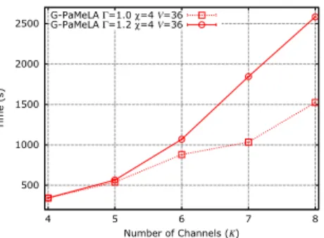
4.2 G-PaMeLA Execution Time vs. Number of Channels . . . 32
4.3 G-PaMeLA and Extended Star Execution Time . . . 33
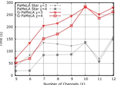
4.4 G-PaMeLA and PaMeLA Execution Time . . . 33
4.5 PaMeLA Execution Time vs. Square-grid Size . . . 33
4.6 Network Packet Loss vs. Γ with γsr= 24 Kbps and V = 36 . . . . 35
4.7 Throughput Fairness vs. Flow Rate with V = 36 . . . 36
4.8 Throughput Fairness vs. Flow Rate with V = 25 . . . 36
4.9 Packet Loss vs. Flow Number for G-PaMeLA and Extended Star . . 36
4.10 Throughput Fairness vs. Flow Rate for G-PaMeLA and Extended Star 36 4.11 Network-wide Packet Loss vs. Number of Channels . . . 37
4.12 Throughput Fairness vs. Number of Channels . . . 37
4.13 Network-Wide Collision Probability with χ = 3 and χ = 4 . . . 38
4.14 Normalized Throughput per Traffic Flow . . . 38
4.15 Packet Loss with γsr = 26 Kbps . . . 39
4.16 Packet Collision Probability with γsr= 26 Kbps . . . 39
4.17 Packet Loss with γsr = 52 Kbps . . . 39
4.18 Packet Collision Probability with γsr= 52 Kbps . . . 39
4.19 Packet Loss with γsr = 104 Kbps . . . 39
4.20 Packet Collision Probability with γsr= 104 Kbps . . . 39
6.1 Spectrum utilization in the United States . . . 46
6.2 Cognition cycle . . . 47
6.3 Cognitive Access and Muti-hop Network Architectures . . . 48
6.4 Cognitive Access Network Architecture . . . 49
7.1 Game Theoretic Approaches . . . 57
8.1 Network Topology Mapped on the San Francisco Bay Area . . . 74
8.2 Fairness Index vs. Number of Channels with 70 web flows and 70 VoIP flows . . . 75
8.3 NoRa vs. MMGMS in terms of convergence cost . . . 76
8.4 Average Throughput vs. Number of CPEs with K = 8 . . . 76
8.5 Throughput vs. BS ID with 28 BSs, 280 CPEs, no DTV changes channel, K = 8 and K = 15 . . . 77
8.6 Throughput vs. BS ID with 28 BSs, 280 CPEs, K = 9 and DTVs
change channels each 15 s . . . 77
10.1 Cognitive Wireless Mesh Network Architecture . . . 86
10.2 Clustered Network. . . 89
11.1 Control Channel Formation Protocol . . . 94
11.2 Cluster Formation Phase . . . 95
11.3 Information Elements in IEEE 802.11 and IEEE 802.22 standards . . 98
11.4 Potential cluster border devices (in yellow). . . 100
12.1 Transmission range vs. number of clusters . . . 104
12.2 Number of C-MDs vs. number of clusters with T xRange = 10 and K = 8. . . 104
12.3 Number of common channels vs. number of clusters with N = 90 and T xRange = 10 . . . 104
12.4 Transmission range vs. relative number of clusters with K = 10. . . 105
12.5 Transmission range vs. number of common channels with K = 10 and N = 30 . . . 105
12.6 Number of C-MDs vs. number of clusters with K = 10 and 5 DTVs changing channels . . . 106
12.7 Time vs. number of clusters with K = 10, N = 45 and 5 DTVs. . . 106
List of Algorithms
1 G-PaMeLA JCAR Phase . . . 19
2 Network Crews . . . 24
3 Post-processing Phase . . . 26
List of Tables
3.1 JCAR Notation . . . 15
3.2 G-PaMeLA Notation . . . 17
3.3 JCAR Problem Variables . . . 19
4.1 Physical Layer Parameter Values . . . 34
List of Acronyms
ACK Acknowledgement Message
AG Auction Game
AODV Ad-hoc On-demand Distance Vector
BDconf Border Device Confirmation
BDinq Border Device Inquiry
BDreq Border Device Request
BG Bargain Game
BS Base Station
CA Channel Assignment
C-AN Cognitive Access Network
CBD Cluster Border Device
CBP Coexistence Beacon Protocol
CBR Constant Bit-Rate
CD Cognitive Device
CFP Cluster Formation Phase
CG Coalitional Game
CHD Cluster Head Device
CLICA Connected Low Interference Channel Assignment
CBM Cluster Beacon Message
CBD Cluster Border Device
C-MD Cognitive Mesh Device
C-MHN Cognitive Multi-Hop Network
CN Cognitive Network
COD Cluster Ordinary Device
Connor Control Channel Formation Protocol
CPE Consumer Premises Equipment
CR Cognitive Radio
C-WMN Cognitive Wireless Mesh Networks
DRR Deficit Round Robin
DTV Digital Television
FCC Federal Communications Commission
FCRA Flow-based Channel and Rate Assignment
GT Game Theory
HeCtor Hedonic Coalitional Formation Game
IE Information Element
ILP Integer Linear Programming
IR Inquiry Request
ISM Industrial, Scientific and Medical
ISP Internet Service Providers
JC Join Confirmation
JCAR Joint Channel Assignment and Routing
KA Keep Alive Message
KAP Keep Alive Phase
LACA Load-Aware joint Channel Assignment and Routing Algorithm
MAC Medium Access Control
MD Mesh Device
MG Minority Games
MMGMS Modified Minority Game with Mixed Strategies
MRMC-WMN Multi-Radio Multi-Channel Wireless Mesh Network
NBS Nash Bargain Solution
NC-AHN Non-Cognitive Ad-Hoc Network
NCN Non-Cognitive Network
NE Nash Equilibrium
NIC Network Interface Card
NoRa Non-cooperative Repeated game
NTU Non-Transferable Utility
OLSR Optimized Link State Routing
OSPF Open Shortest Path First
PaMeLA Partitioned Mesh Channel Assignment
PG Potential Game
PU Primary Users
QoS Quality of Service
SDSE Strongly Dominant Strategy Equilibrium
SG Stochastic Game
SU Secondary User
TU Transferable Utility
TVWS TV White Space
U-NII Unlicensed National Information Infrastructure
UP Update Message
UWB Ultra Wide Band
VoIP Voice over IP
WMN Wireless Mesh Network
WRAN Wireless Regional Area Network
List of Symbols
R Real Numbers
T(t1, t2) The larger set of devices transmitting in the time
interval [t1, t2]
W Background noise power
Pi,j Received power at device j when device i is
trans-mitting
PT Transmitted power
PM ax Maximum transmission power at the MAC layer
∆i,j Euclidean distance between devices i and j
η Path loss exponent for propagation in free space
λ Signal’s wavelenght
γj Capture threshold of device j
G(V, E) Physical topology in MRMC-WMN V Set of devices in MRMC-WMN V Number of devices in MRMC-WMN E Set of edges in MRMC-WMN E Number of edges in MRMC-WMN K Set of channels K Number of channels Θ Set of gateways
χp Number of NICs for the device p ∈V
Λ Maximum link utilization
Γ Maximum routing path length
Ψkpq Nominal data rate of link epqon channel k
S Set of sender-receiver flow pairs
γs,r Traffic load from the sender device s to the
re-ceiver device r
β Interference threshold
Ip Distance in number of hops between p and the
furthest device to p in G(V, E)
Ωd,p Set of d-hop neighbors to the device p ∈V, with
d = {0, 1, . . . ,Ip}
|Ωd,p| Number of d-hop neighbors to the device p ∈V
hG
sr Minimum number of hops between devices s and
r in G(V, E)
Ξ Set of network crews
Z Number of network crews
C Set of ways to split the network
|C | Number of ways to split the network
R Set of ranking functions
|R| Number of ranking functions
U Set of criteria to assign channels to unused NICs
|U | Number of criteria to assign channels to unused
NICs
P Set of JCAR sub-problems
Pc,r(d) ILP formulation ofPc,r with d = {0, 1, . . . ,Ip− 1}
σ Set of solutions of the JCAR problem
¯
σ Best solution of the JCAR problem
σu
c,r Solution of the JCAR problem with c ∈C , r ∈ R
and u ∈ U
Θ Set of gateways
|Θ| Number of gateways
xkpq Logical topology, 1 if device p communicates with
device q over the channel k and 0 otherwise
G∗(G) Logical topology graph, i.e. links for which xk
pq=
1 yk
p Interface assignment, 1 if ∃p ∈ V and epq ∈ E
such that xk
pq= 1 and 0 otherwise.
yg,pqk Interference, 1 if ∃g, p ∈ V and epq ∈ E such
that yk
g = xkpq= 1 over the same channel k and 0 otherwise.
ψkpq Effective capacity of a logical link
ρkpq,sr Binary routing, 1 if the traffic from device s to
device r is being routed via link epqover channel k and 0 otherwise
λkpq Aggregate traffic, i.e. sum of the traffic on link
epq over channel k
µsr Path existence, 1 if a path exists between devices
s and r in G∗(G) and 0 otherwise
hGpq∗ Path length, number of hops between devices s
and r in G∗(G)
Dtot Total interference weighted on the traffic load
and the distance from the gateway
G = {N, S, U} Game
N Set of devices (Players in game theory)
L Set of cognitive devices (BSs and CPEs)
M Set of CPEs
Mi Set of CPEs belonging to BS i ∈N
S Set of Strategies
Si Set of strategies for player i ∈N
U Set of Utility Functions
Ki Set of available channels for device i ∈N
BWi Backoff window for player i ∈N
BCi Backoff counter for player i ∈N
ni Number of WRANs sensed by a player i
C Coalition structure
C Number of coalitions
Cp A specific coalition, with p ∈ {1, . . . , C}
Cp Cardinality ofCp
v(Cp) Coalition Value of Cp
maxC Maximum coalition dimension size
max∆ Maximum distance among devices belonging to
the same coalition xx
∆Cp,i Distance between the furthest player in coalition Cp and player i
COld Current coalition
CN ew Future coalition
gi Gain for player i ∈N
oi Complexity for player i ∈N
I Set of Internet Service Providers I = {ISP0,
ISP1, ISP2}
B Set of clusters
B Number of clusters
Bp A cluster with p = {1, . . . , B}
Bp Number of C-MDs in the clusterBp
Hp Cluster head ofBp
KBp Set of available channels of clusterBp
KBp Number of channels inKBp
M axT xRx Maximum number of consecutive CBMs
trans-mitted by a C-MD on the same channel
max∆ Maximum number of hops admitted into a cluster
max∆Bp Maximum number of hops in the clusterBp
TIR Timeout of the IR message
TJ C Timeout of the JC message
TU P Timeout of the UP message
wi Weight of C-MD i
µu Number of hops from the two furthest C-MDs in
Bu
ρi Number of hops between i and the furthest C-MD
in its cluster
You gotta find what you like and let it kill you.
Kinky Friedman
1
Introduction
In recent years there has been a wide proliferation of wireless applications and ser-vices which has led to the fundamental and challenging spectrum shortage problem. In this work we analyze the spectrum shortage problem under different scenarios proposing solutions for traditional technologies, that is multi-radios multi-channels wireless mesh networks (MRMC-WMNs), and emerging technologies, that is cogni-tive networks (CNs) and cognicogni-tive wireless mesh networks (C-WMNs).
Part I analyzes how to improve the usage of unlicensed wireless resources studying the join channel assignment and routing problem in MRMC-WMNs, then Part II and Part III analyze issues and solutions to opportunistically use licensed resources in CNs and C-WMNs, respectively. Conclusions and considerations on future directions are drawn in Part IV.
Wireless mesh networks (WMNs) are an emerging and recently widely available technology providing high-bandwidth networks in industrial and residential settings. The opportunity to equip a single mesh device (MD) with multiple radios is seen as a key to improve network performance [108]. In fact, by setting the radios on orthogonal (non-overlapping ) channels, multiple packets can be transmitted over-the-air simultaneously without colliding with one another. Hence, introducing the so called MRMC-WMNs. Although equipping a MD with multiple radios is not an issue from a financial point of view, a conclusive solution concerning how to assign different channels to these devices has so far not been found. In the literature the way to assign channels to radios, in order to improve the aggregate throughput of the network, is termed channel assignment (CA). There are two research issues that need to be addressed when channel assignment algorithms in MRMC-WMNs are applied: routing and limited number of radios for each MD. In fact, depending on how channels are assigned to radios, different paths with different characteristics could be found. For these reasons, the processes of routing and channel assignment are very much inter-related and hence are considered jointly in the literature under the name of Joint Channel Assignment and Routing (JCAR) problems. The JCAR problem is NP-hard, hence several heuristic approaches have been proposed in the literature. After a general overview on channel assignment approaches for MRMC-WMNs in Chapter 2, we review several JCAR solutions in Chapter 3 and then we compare their performance in Chapter 4 through an extensive simulation study. Conclusions are presented in Chapter 5.
Unfortunately even if different channels are assigned to multiple radios per device, MRMC-WMNs result in what is called spectrum overcrowding. In order to address
the spectrum overcrowding problem, careful analysis on spectrum frequencies has been conducted. These studies have led into the identification of unlicensed and licensed channels which are differently utilized. In particular, licensed channels result to be surprisingly underutilized [37] compared to unlicensed channels. For this reason, the networking community is studying and addressing the resources’ problem through the creation of CNs which are seen as the answer to the spectrum overcrowding.
Cognitive networks [71] have been proposed to have easily maintainable networks that are continuously improved and upgraded by relying as little as possible on hu-man intervention. CNs opportunistically operate in licensed channels allocated to the TV broadcasting service, supplying to the unlicensed spectrum scarcity, and are characterized by a high level of flexibility given by their ability in sensing the current environment, planning for the future, making decisions and acting accordingly. CNs have been first thought as access networks which consider point-to-multipoint com-munication paradigms where a base station supports multiple end-users and provides access to the Internet in rural and remote areas. Then the concept of CN has been extended to industrial and residential settings and hence mesh capabilities have been added. In Part II and Part III, we address the main problems that afflict cognitive access (C-AN) and mesh (C-WMN) networks, respectively.
Part II is dedicated to the major challenge in implementing cognitive access net-works, which is the coexistence among network devices of the same type, known as self-coexistence and which can be addressed as a channel assignment problem. The major difference between how to address the channel assignment problem in traditional wireless networks and cognitive networks is the time and space variability of the set of accessible channels for each device. In Chapter 6, we introduce gen-eral concepts on CNs illustrating terminology and challenges. Then in Chapter 7, we address the self-coexistence in C-ANs as a channel assignment problem using game theoretic approaches. First, we propose Nora which takes into consideration non-cooperation among self-interested cognitive devices, then we propose HeCtor, which considers the possibility to have groups of cooperative cognitive devices. Nora and HeCtor are evaluated in Chapter 8 along with algorithms from the literature. Conclusions are drawn in Chapter 9.
Concluding in Part III, we analyze issues related to cognitive wireless mesh net-works identifying as the most important, the coordination problem among cognitive mesh devices (CMDs). In fact, the several functionalities needed in order to man-age a CN (spectrum sensing, spectrum decision, and spectrum sharing) all require exchange of information and hence a coordination mechanism among devices. The coordination problem can be addressed assuming the existence of a centralized con-trol entity or implementing a concon-trol message exchange mechanism. The existence of a centralized control entity in C-WMNs is not guaranteed because CMDs form a multi-hop backbone tier and hence there are not guarantees on the existence of a connection from each CMD to the centralized control entity. The control mes-sages exchange, instead, is a suitable solution for C-WMNs but it is not without challenges particularly since CMDs experience spectrum variability over time and lo-cation and therefore a fixed control channel suitable for every CMD could not exist. We propose Connor, a clustering algorithm based on local common control channels, which addresses the coordination problem among CMDs as an exchange control mes-sages problem. Connor does not require synchronization among CMDs and allows 2
a fast re-clustering when changes occur in channel’s occupancy by licensed users. In Chapter 10, we introduce general concepts and terminology of C-WMNs, and in Chapter 11 we analyze the coordination problem along with the description of Con-nor. The performance of Connor are presented in Chapter 12 and conclusions are drawn in Chapter 13.
Summarizing, spectrum shortage and overcrowding problems have been addressed in this work under several conditions and assumptions with the objective of handling the growing demand of wireless resources in rural, remote as well as industrial and residential areas.
Part I
Channel Assignment in
Multi-Radio Multi-Channel
I have not failed. I’ve just found 10,000 ways that won’t work.
Thomas A. Edison
2
Multi-Radio Multi-Channel
Wireless Mesh Networks
2.1 Introduction
Wireless Mesh Networks (WMNs) are an emerging and recently widely available technology providing high-bandwidth networks in industrial and residential settings. WMNs have been originally developed for military applications but, thanks to decre-ment in size, cost, and power requiredecre-ments of mesh devices (MDs), they are becoming every day more popular as access network paradigms.
A WMN consists of backbone devices and end-users as shown in Fig. 2.1 (See [5] for a survey). As backbone devices we identify mesh routers and mesh gateways, which are fixed and form multi-hop wireless links between end-users and the Internet. Mesh gateways are mesh routers with Internet connectivity. End-user devices, on the other hand, are typically mobile or nomadic mesh clients. Each mesh client is connected to a backbone device in order to have its packets forwarded from/to the Internet. We focus on the backbone tier alone with the aim of achieving a higher performance using different chunks of the frequency spectrum to connect backbone devices among them in a multi-hop fashion.
A chunk of the frequency spectrum is commonly called channel and the problem to assign channels to backbone devices in order to avoid co-channel interference among them is referred as channel assignment (CA) problem. In recent years, the possibility of equipping a single backbone device with multiple radios has became a reality. Hence, a new class of WMNs using multiple channels and multiple radios has been identified and referred under the name of multi-radio multi-channel wireless mesh network (MRMC-WMN). MRMC-WMNs are characterized by the ability of transmitting on different channels and by backbone devices equipped with more than one radio each. In MRMC-WMN, the CA problem is seen as the way to allocate channels to radios in order to improve the aggregate throughput of the network.
2.1.1 Outline of the Chapter
The remaining of the chapter is organized as follows. Section 2.2 analyzes the chan-nel assignment problem in MRMC-WMNs, Section 2.3 describes the most common interference models used in the literature in order to analyze interactions among
Figure 2.1: Wireless Mesh Network Architecture
wireless devices and Section 2.4 gives some terminology regarding network topolo-gies.
2.2 The Channel Assignment Problem
The opportunity of equipping a single backbone device with multiple radios, called Network Interface Card s (NICs), is seen as a key to improve the network performance [108]. In fact, by setting the radios on orthogonal (non-overlapping ) channels, mul-tiple packets can be transmitted over-the-air simultaneously without colliding with one another. For example more frequency diversity can be allocated to those areas of the WMN that are expected to have a higher load. Although equipping a device with multiple NICs is not an issue from a financial point of view, a conclusive solution concerning how to assign different frequency bands to these devices has so far not been found. Moreover, to reduce contention and interference, randomly assigning channels to NICs or equipping nodes with a number of NICs equal to the number of allowable channels, are not efficient choices. A random assignment is not efficient because a node should minimize the number of neighbors sharing a common chan-nel, while at the same time maintaining topological connectivity. Unfortunately, a random channel assignment cannot give these guarantees. A high number of radios, on the other hand, does not address the limited number of channels and routing problems. In fact, if the number of neighbors for a node is greater than the number of channels, then the node has to choose the appropriate neighbors that will share a common channel. In addition, equipping a node with a number of NICs equal to the number of channels does not solve the routing problem because it does not address how to choose a channel for a packet transmission.
A typical technology exploited to implement WMNs is the IEEE 802.11 standard where non-overlapping channels are assigned to NICs in order to enable transmissions. IEEE 802.11b and IEEE 802.11g standards [1] use the 2.4 GHz industrial, scientific and medical (ISM) band which is divided into 13 channels of which only 3 are orthogonal. Because of the frequency band choice, IEEE 802.11b and g equipment 8
may occasionally suffer interference from microwave ovens, cordless telephones and Bluetooth devices with the result that they become crowded. Instead IEEE 802.11a standard [1] uses the 5 GHz unlicensed national information infrastructure (U-NII) band, which offers at least 12 non-overlapping channels rather than 3, thus providing a significant advantage. In practice the number of allowable channels is regulated by each country based on how the radio spectra are allocated to various services (See [1] for more details). To simplify our explanation, we consider 12 as a maximum number of non-overlapping channels. The IEEE 802.11 technology does not provide native support for multi-hop forwarding and channel assignment. In spite of this most WMNs are made up of off-the-shelf IEEE 802.11 devices, because of their widespread availability and very low cost. For this reason within the IEEE 802.11 working group, a task group s has been created in order to amend the standard and add the missing multi-hop functions. While the standardization process has not yet finished [2], the IEEE 802.11s draft is supported by a wide variety of industry leaders and is available as part of the 802.11 MAC layer in the most recent Linux kernels and FreeBSD.
2.2.1 Research Issues
There are two research issues that need to be addressed when CA algorithms are applied to MRMC-WMNs:
(i) Routing protocol, i.e. the process to select paths from sources to destinations. (ii) Limited number of NICs for each router.
It is well-known that existing routing protocols for wired networks, such as the Open Shortest Path First (OSPF), are either inadequate or inefficient for WMNs [36]. Therefore, routing protocols from the domain of ad-hoc wireless networks, such as Ad-hoc On-demand Distance Vector (AODV) or Optimized Link State Routing (OLSR), are commonly adopted in WMNs with good results [36]. However when we change our focus from a WMN to MRMC-WMN more routing scalability and robustness are required [5]. In fact, depending on how channels are assigned to NICs, different paths with different characteristics could be found and the number of hops between two nodes can increase without any control. This behavior is caused by the fact that, in a multi-channel environment, two nodes can communicate only if they are in the transmission range of one another and they have at least one NIC tuned on a common frequency band. Additionally, channel assignment and routing both depend on the traffic load distribution. For these reasons, the processes of routing and channel assignment are very much inter-related and hence are considered jointly in MRMC-WMN under the name joint channel assignment and routing (JCAR) problem.
2.3 Interference Models
An interference model describes how devices influence each other, hence it is essential in order to model channel assignment algorithms among wireless devices. We identify two interference models: protocol and physical interference models.
The protocol interference model is a binary paradigm where interferences are con-sidered on a pair basis and hence it provides a simple and easily tractable approach. However, the protocol interference model fails in properly capture the interference generated by the entire network. In fact, using a binary model it is possible associate at each device the exact number of overlapping competitors, but doing so, some solutions are ruled out. For example the protocol interference model do not consider solutions where two devices do not interfere, however if a third one is transmitting on the same channel, then the interference destroy the communication.
The physical interference model [110], instead, is a cumulative paradigm and hence capture how the entire network influence a single devices guaranteeing a more realistic model of the interactions among devices. Usually the physical interference model use the Signal to Interference and Noise Ratio (SINR) as in Eq. (2.1).
SIN Ri,j(t1, t2) = Pi,j P h∈T(t1,t2)\i Ph,j+W (2.1)
Here T(t1, t2) is the larger set of devices transmitting in the time interval [t1, t2]; W is the background noise power. The received power depends on the Euclidean distance ∆i,j, in meters, between devices i and j; the transmitted power PT; the path loss exponent η; and, the signal’s wavelength λ in meters:
Pi,j=
PT(λ/4π)2
∆ηi,j . (2.2)
To effectively capture transmissions the SINR on the receiver device (j) has to be greater than or equal to its capture threshold, indicated by γj.
In an MRMC-WMN architecture, interference is often modeled with a protocol interference model to simply the JCAR problem. However, the protocol model does not correctly capture the cumulative nature of the interferences in a wireless environ-ment, hence a physical interference model is preferred in order to consider the effect of cumulative interference from multiple devices transmitting at the same time on a single device.
Regarding to how devices can tolerate interference, a protection and a pollution viewpoints have been defined in the literature [98]. Protection means that a device can only operate in locations where it cannot generate any interference to other devices. In contrast, pollution allows interference under a given threshold to be non-disruptive. To establish these thresholds, a device needs to have knowledge regarding other devices, which may or may not be possible depending on its type and location.
2.4 Terminology of Network Topologies
Due to the nature of MRMC-WMNs, we distinguish between physical and logical topologies which consist of physical and logical links, respectively.
A physical link exists between any two devices if they are in the transmission range of one another. Two devices that share a physical link are called one-hop neighbors (or neighbors for short), while two devices that have a common neighbor, but are not neighbors themselves are called two-hop neighbors.
A logical link between two devices is characterized by the following properties: (i) there is a physical link between them, (ii) they have at least one NIC set to the same channel, and (iii) there is at least one traffic flow traversing them.
The set of physical links forms a physical topology, while logical links forms a logical topology.
Finally, we introduce the concept of connected network. A network is considered connected if at least one path exists between any pair of devices. The definition of disconnected network follows.
Do not wait for leaders; do it alone, person to person.
Mother Teresa
3
The Channel Assignment Problem
3.1 Introduction
The JCAR problem is seen as a key problem in the context of MRMC-WMNs, as also highlighted by the amount of work that has recently appeared in the literature. Traditionally, the CA problem has been mapped on to the well-known graph coloring problem, i.e., to find the minimum number of colors assigned to devices in a graph such that two adjacent devices never have the same color [22]. While such an approach is important from a theoretical point of view, its applicability remains somewhat limited in practical terms, because of network-specific constraints and objective functions. For example, the number of colors that all the neighbors can have is limited by the number of NICs that a node has and it is difficult to capture a traffic load and/or cumulative interference models in a straightforward manner. Moreover the graph coloring problem as well as the JCAR problem areNP-hard and there is no known algorithm to find the optimal solution in a reasonable amount of time (polynomial time with the network size) for non-trivial MRMC-WMNs.
In recent years, JCAR problems have been modeled following different approaches, which we can broadly classify into three categories.
(i) Optimization approaches: which are proved to be NP-hard, then solved by relaxing constraints or using heuristic sub-optimal algorithms [78, 91].
(ii) Empirical approaches: whose effectiveness is typically verified through simula-tion [73, 93, 92, 12, 64, 107].
(iii) Mixed approaches: which are formulated as local optimization problems and then combined following empirical approaches [42].
3.1.1 Outline of the Chapter
The chapter is organized as follows. Section 3.2 introduces the system model, Sec-tion 3.3 illustrates mathematical optimizaSec-tion approaches proposed in the literature to address the JCAR problem, Section 3.4 describes several empirical algorithms and Section 3.5 proposes G-PaMeLA, a mixed approach.
3.2 System Model
System model and assumptions described in following are typical of JCAR prob-lems presented in the literature, where has been assumed that the centralized entity running the CA algorithm knows the following configuration parameters.
(i) Physical topology (see Section 2.4). It is represented as a graph G(V, E) where V is the set of devices and E is the set of unidirectional physical links. We indicate with V and E the cardinality of setsV and E, respectively. Hereafter hG
srindicates the shortest path, in a number of hops, from device s to device r in G(V, E).
(ii) The number of NICs of device p, say χp. We assume χ1 = χ2 = · · · = χV to simplify the notation but without loss of generality, and this number is indicated with χ. Thus, the set of allowable channels isK = {1, 2, · · · , K}. As previously mentioned, the number of allowable channels may be different in different countries. For sake of simplicity, we consider K ≤ 12. In fact, we have to add to the constraint given by each country, environmental constraints where some channels could be used by neighboring networks or end-users. For these reasons we analyze the behavior of CA algorithms in configurations with different numbers of allowable channels. The limited number of channels implies that, with the exception of very small networks, some logical links must be assigned to the same channel, i.e. these links cannot be simultaneously active. We did not analyze the link scheduling problem in MRMC-WMNs [68] but we are considering to include this feature in a future study.
(iii) Received power, channel rates, and traffic loads. The concept of received power Pp,q is defined in Eq.(2.2) and is closely related to the interference as explained in Section 2.3. The channel rate Ψk
pq represents the nominal data rate of the link epqon channel k ∈K. For instance, the IEEE 802.11a standard uses a 52-subcarrier orthogonal frequency-division multiplexing (OFDM) with a maximum raw data rate of 54 Mbps, which could be reduced to 48, 36, 24, 18, 12, 9 or 6 Mbps if required. With regard to both the received powers and the channel rates, WMN devices are static, hence channel conditions are quite stable [21]. An estimation of the physical layer status was investigated in [60] and it is not considered further in this study. Lastly, the set S contains all the sender-receiver flow pairs and its cardinality is the number of traffic flows through the network. Each traffic load from any sender device s to any receiver device r is γs,r and is either available as a priori knowledge, based on historical data, or estimated while the WMN is operating.
We further define Ωd,p as the set of devices at distance d, in a number of hops, from the device p taking into account G(V, E). If |Ω0,θ| = 1 then the unique element ω0,θ in this set is the gateway, i.e. ω0,θ = θ, and each element ω1,θ ∈ Ω1,θ is a one-hop neighbor to the gateway (sub-gateway ). Follow that Ω1,θ is the set of sub-gateways. Notations used in the JCAR problems illustrated in this Part are shown in Table 3.1.
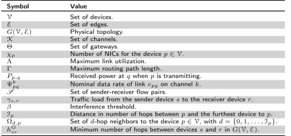
Table 3.1: JCAR Notation. Symbol Value V Set of devices. E Set of edges. G(V, E) Physical topology. K Set of channels. Θ Set of gateways.
χp Number of NICs for the device p ∈V.
Λ Maximum link utilization.
Γ Maximum routing path length.
Pp,q Received power at q when p is transmitting.
Ψk
pq Nominal data rate of link epqon channel k.
S Set of sender-receiver flow pairs.
γs,r Traffic load from the sender device s to the receiver device r.
β Interference threshold.
Ip Distance in number of hops between p and the furthest device to p.
Ωd,p Set of d-hop neighbors to the device p ∈V, with d = {0, 1, . . . , Ip}.
hG
sr Minimum number of hops between devices s and r in G(V, E).
3.3 Optimization Approaches
JCAR problems formulated as mathematical optimizations have the objective of finding the the best solution from a set of available alternatives. In this context we summarize two works extracted from the literature [78, 91].
Mohsenian et al. [78] formulates the JCAR problem as an ILP problem and as a heuristic algorithm but the results are only shown for the heuristic formulation due to the inherent complexity of the JCAR problem. Hence, in the heuristic algorithm they trade the accuracy of the solution for a (much) faster execution time. Their algorithm is based on randomly choosing the initial solution and then refining it within a limited number of configurable steps. Constraints and objective function of the problem in [78] are adapted to the local sub-problem summarized in Section 3.5. Ramanathan et al. [91] proposed an unified framework to efficiently assign chan-nels to devices or links in order to achieve the most efficient spatial reuse. Their formulation is based on a graph coloring problem, hence the execution time of their algorithms is high. For this reason they also proposed distributed versions.
3.4 Empirical Approaches
Empirical algorithms are formulated based on information gained by means of obser-vations, experiences and experiments.
Marina et al. [73] proposed the Connected Low Interference Channel Assignment (CLICA), which is based on the use of a conflict graph and a protocol interference model. Kyasanur et al. in [64] proposed a JCAR algorithm suitable to be performed by a central server that periodically and dynamically collects channel interference information. However, [73] and [64] do not consider the traffic load on links.
Skalli et al. [107] formulated a fixed, rank based, polynomial time, greedy algo-rithm for centralized channel assignment where the rank of each device is computed based on its link traffic characteristics. Unfortunately this technique is difficult to apply if channel assignment and routing are considered jointly. In fact, the algorithm in [107] is based on a traffic matrix which assumes a priori knowledge of the routing
algorithm. Clearly, when channel assignment and routing are done jointly, the traffic matrix is not known a priori.
The following solutions have the same objective as G-PaMeLA, hence they are evaluated for comparison purposes in the performance analysis in Chapter 4.
First, Raniwala et al. [93] proposed a centralized heuristic Load-Aware joint Channel Assignment and routing algorithm (LACA), which is specifically used for wireless Internet access applications. Given the set of initial link flow rates, LACA assigns channels in the attempt to have a proportional relation between flow rate and available bandwidth on each link. The available bandwidth values are estimated as a fraction of the link capacity and are used as inputs to the routing algorithm, which computes the shortest path for every flow. The resulting flow mapping on each link is used as a link flow rate for the next iteration, in which a new channel assignment is computed. The algorithm in [93] does not tie to any specific routing mechanism.
The same authors also proposed Hyacinth [92], which is constructed with a multiple spanning tree-based load balancing routing algorithm that can be adapted dynamically to a traffic load. The channel assignment problem is divided into two problems, i.e. neighbor-to-interface and an interface-to-channel binding problem. In this logical tree topology, each gateway is a root and each router uses an up-NIC to exclusively connect to its parent, and uses several down-up-NICs to connect to its children. Each parent router provides Internet connectivity to its children (routers), that is each wireless mesh router can access the Internet through the shortest available routing path. In Hyacinth, each router allocates the channels that are the least used by its neighboring routers to down-NICs. The channel assignment to devices positioned higher in the tree affects all devices lower in the tree hierarchy thus creating a non-robust CA due to ripple-effects.
Finally, in [12] the authors proposed the Flow-based Channel and Rate Assign-ment (FCRA) algorithm. FCRA is a centralized channel and rate assignAssign-ment algo-rithm, which starts from a network mapped on an individual channel, which then improves the performance by adding different channels where possible. The FCRA algorithm does not require knowledge of the traffic demands and provides both a channel and a transmission rate for each link, taking into account the network-wide effect of such a choice.
3.5 Mixed Approach: G-PaMeLA
We propose our mixed approach to the JCAR problem, which is a divide-and-conquer scheme called Generalized Partitioned Mesh network traffic and interference aware channeL Assignment (G-PaMeLA).
The core of our scheme consists of solving a sequence of sub-problems in a given order and combining them using a post-processing procedure. Each sub-problem is much simpler than the global JCAR problem, because only the local constraints on interference are tested. A sub-problem is solved using a hybrid approach between a branch-and-bound and cutting plane, i.e. the branch-and-cut method [25]. The latter method is used to solve the ILP problems with the regular simplex algorithm, where some unknowns are restricted to integer values. In addition, we take into 16
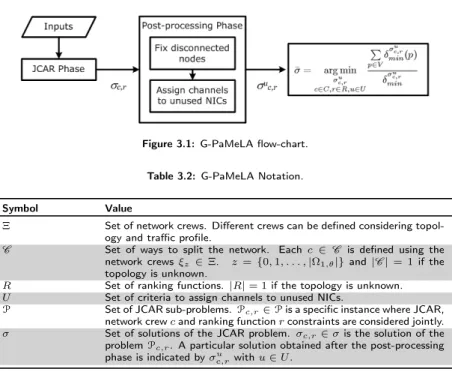
Figure 3.1: G-PaMeLA flow-chart. Table 3.2: G-PaMeLA Notation.
Symbol Value
Ξ Set of network crews. Different crews can be defined considering
topol-ogy and traffic profile.
C Set of ways to split the network. Each c ∈ C is defined using the
network crews ξz ∈ Ξ. z = {0, 1, . . . , |Ω1,θ|} and |C | = 1 if the
topology is unknown.
R Set of ranking functions. |R| = 1 if the topology is unknown.
U Set of criteria to assign channels to unused NICs.
P Set of JCAR sub-problems.Pc,r∈P is a specific instance where JCAR,
network crew c and ranking function r constraints are considered jointly.
σ Set of solutions of the JCAR problem. σc,r∈ σ is the solution of the
problemPc,r. A particular solution obtained after the post-processing
phase is indicated by σc,ru with u ∈ U .
consideration the physical interference model (see Section 2.3) to address interference problem among devices.
We assume that a centralized entity, co-located with the gateway, exists and we dedicate the use of a NIC for control purpose. Hence, we assume the existence of a control channel common to all the backbone devices. Periodically, the gateway uses G-PaMeLA to assign channels and to determine the routing paths in the MRMC-WMN. In addition, the gateway is responsible for disseminating the updated channel assignment and routing to all devices using the control channel. The procedure is provided with input on the configuration parameters and the current status of the MRMC-WMN, which can be retrieved by means of a network management protocol running in the MRMC-WMN. The network functions that collect data from devices to the centralized entity and enforce channel assignments and routing that it produces, are outside the scope of our work, which focuses only on the algorithm that it runs. Thanks to the load balancing property of G-PaMeLA, we assume that the MRMC-WMN also acts appropriately if the traffic load changes, in fact in each link there is room free for additional flows.
We consider a set of gateways Θ to the Internet. Clearly we can trace the problem back to the case |Θ| = 1 in fact if |Θ| > 1 then the overall JCAR problem can be divided into |Θ| sub-JCAR problems where each takes into account the channel assignment made by the others. The devices are assigned to each sub-JCAR problem based on a combination of factors, including the distance from the gateway and the traffic load. Hereafter, to simplify the explanation and without loss of generality we consider |Θ| = 1 and we indicate the gateway as θ ∈ Θ.
The divide-and-conquer strategy, on which G-PaMeLA is based on, consists of breaking one problem into smaller, more manageable sub-problems, and then taking control of these sub-problems one by one. This strategy is therefore a powerful tool
for conceptually solving complex problems like the JCAR problem.
The technique used to break down the JCAR problem into sub-problems is man-aged from the first phase of G-PaMeLA, called JCAR phase. The second phase, called post-processing phase, instead combines the outcomes of the related sub-problems. The best solution ¯σ is selected from all the solutions σu
c,r according to a max-min fairness criterion combined with a load-aware interference objective. The G-PaMeLA flow chart is shown in Fig. 3.1 and the notations used throughout this Section are summarized in Tables 3.1 and 3.2. We now provide a formal description of the two phases separately.
3.5.1 JCAR phase
The JCAR phase uses an inner core procedure, which finds the optimal solution of a sequence of sub-problems which are formulated as an ILP problem and are solved following the order given by a ranking function. The output of each sub-problem defines the channel assignment and routing local to the devices associated with this sub-problem.
The divide-and-conquer approach entails splitting the overall problem into several sub-problems, thus in the JCAR phase we divide the devices into sets. Devices in the same set are characterized by a common property which could be, for example, the number of hops to the gateway. In this case the number of sets is equal toIθ. As previously explained, we can then reduce the number of JCAR sub-problems toIθ−1. The time needed to solve the global ILP problem with G-PaMeLA is given by the sum of the time required to solve theIθ− 1 sub-problems. No additional time is required to unify the sub-problems because each sub-problem is solved under the constraints given by the sub-problems already solved. To decide the set of devices associated with a sub-problem, the JCAR phase defines a property that each device satisfies. If the centralized entity performing G-PaMeLA is not aware of the physical topology pattern (unknown topology ), then the property is defined as the number of hops between the device and the gateway and therefore the number of ranking functions is equal to 1. That is, we solve an ILP problem for each Ωd,θ where d = 0, 1, . . . ,Iθ. On the other hand, if the topology refers to well-known patterns such as grids or stars (known topology ), the JCAR phase can define different properties and therefore several ranking functions. The details driving the choice of using a ranking function are described in the following.
Due to the limited number of constraints, the sub-problems are solved optimally in a shortened amount of time with standard solvers, e.g., using branch-and-cut tech-niques [70], making our JCAR solution feasible for an operational network. Moreover, multiple instances of the inner core procedure could be run, each one enforcing dif-ferent routing constraints via so-called network crews. However, if the topology is unknown the number of combinations of network crews is |C | = 1 because the con-struction of each crew is based only on the number of hops. The crews’ concon-struction and motivations are later detailed.
At the end of the JCAR phase we obtain a set σ of JCAR solutions, one for each ILP problem in the set P. Let us indicate with σc,r ∈ σ the solution of the JCAR problemPc,r ∈P solved by following the ranking order r ∈ R and under the constraints given by c ∈C .
We conclude this section by formulating the ILP problem and explaining working 18
Algorithm 1 G-PaMeLA JCAR Phase: pseudo-code.
1: procedure JCAR
2: letP0be a JCAR problem with basic constraints andPc,r(−1) = ∅
3: compute r ∈ R and c ∈C
4: for c ∈C do
5: Pc=P0+ constraints due to c
6: for r ∈ R do
7: for all d = {0, 1, . . . ,Iθ− 1} ordered as r do
8: σc,r(d) = solve {Pc,r(d)} underPc,r(d − 1) 9: end for 10: end for 11: end for 12: σ = S c∈C ,r∈R σc,r(Iθ− 1) 13: end procedure
Table 3.3: JCAR Problem Variables.
Symbol Name Definition
xkpq Logical topology It is 1 if device p communicates with device q over
the channel k, 0 otherwise.
G∗(G) Logical topology graph It is derived from the graph G(V, E) and consists of
all the links for which xkpq= 1.
ypk Interface assignment It is 1 if ∃p ∈V and epq∈E such that xkpq= 1,
0 otherwise.
yg,pqk Interference It is 1 if ∃g, p ∈ V and epq ∈E such that ykg =
xk
pq= 1
over the same channel k, 0 otherwise.
ψk
pq Effective capacity
of a logical link
It depends on the traffic that crosses the link epq∈E
and on the number of NICs over channel k. ρkpq,sr Binary routing It is 1 if the traffic from device s to device r
is being routed via link epqover channel k, 0
other-wise.
λk
pq Aggregate traffic Sum of the traffic on link epq over channel k.
µsr Path existence It is 1 if a path exists between devices s and r in
G∗(G), 0 otherwise.
hG∗pq Path length Number of hops between devices s and r in G∗(G).
variables, tunable parameters and constraints. For the sake of brevity, we report the workflow as a pseudo-code in Algorithm 1 using mathematical notations.
An ILP instance of the problemPc,r, indicated asPc,r(d) with d = {0, 1, . . . ,Iθ− 1}, is formulated including the routing constraints from the network crew c (line 5), and all the constraints on routing, capacity, and interference that affect the one-hop neighborhood of the Ωd,θ set. Additionally,Pc,r(d) needs to take into consideration the selected paths for sets that have already been solved (line 8).
The solution σc,r of the ILP problemPc,r is finally obtained by putting together all the channel assignment and routing choices in all the instances. The maximum number of JCAR solutions at the end of the JCAR phase, and passed to the post-processing phase, is |C | × |R|, which is 1 if the topology is unknown.
Table 3.3 summarizes the many working variables used by the ILP problem, whereas the tunable parameters are defined as follows:
• Λ is a value in the range (0, 1] which represents an upper bound on the ex-pected link utilization. In fact, in existing networks the channel rate cannot be used entirely due to the Medium Access Control (MAC) and the Physical layer’s overhead, including headers, collisions, inter-frame spaces, preambles, and antenna switching gaps. With the help of Λ we force G-PaMeLA to only
use a fraction of the nominal data rate Ψk
pq, ∀epq∈E and ∀k ∈ K, by leaving room for any such overheads.
• Γ is an upper bound on the routing path length and its value is greater or equal to 1. With the help of Γ we force the inclusion of those routing paths that are longer, in terms of the number of hops, than the shortest ones computed in G(V, E). Let us take a binary variable µsr that is 1 if device s can reach device r in the logical topology, 0 otherwise. It is clear that µsris always equal to 1 in the physical topology. Let hG∗
sr be the path length between devices s and r in G∗(G). If Γ = 1.5 and hG
sr = 4 then all the paths where hG
∗
sr ≤ 6
are considered eligible. As a special case, if Γ = 1 only paths of the minimum length are allowed.
• β represents the resilience to interference, which in turn depends on path-loss and all the environment variables analyzed in Eq. (2.1). With the help of β, we decide how strict G-PaMeLA is with respect to the assumption that given a device p the devices in the setS
d=0,...,IpΩd,p may or may not interfere with
transmissions to p. Decreasing β means increasing the spatial re-use and the number of concurrent transmissions in the network and hence interference. It is unlikely that the non-predictable behavior forces us to make assumptions as in the ILP formulation in Fig. 3.2.
Λ and Γ have already been proposed in the literature (e.g., [78]), β instead, is a peculiarity of G-PaMeLA, in fact it is closely related to the physical interference model used.
Figure 3.2: G-PaMeLA: ILP formulation ofPc,r(d). find max δmin(t) ∀t ∈ Ωd,θ (3.1) δmin(t) = min epq ∈Ed; k∈K; xkpq =1 (Λ · Ψk pq− λkpq), ∀epq∈Ed; ∀k ∈K (3.2)
Channel allocation constraints
xkpq= xkqp, ∀epq∈Ed; ∀k ∈K (3.3) P k∈K yk p≤ χ, ∀p ∈ S i=d,d+1,...,Iθ−1 Ωi,θ (3.4) yk p≤ P epq ∈Ed xk pq, ∀p ∈ S i=d,d+1,...,Iθ−1 Ωi,θ; ∀k ∈K (3.5) xk pq≤ y k p, ∀epq∈E : p ∈ S i=d,d+1,...,Iθ−1 Ωi,θ; ∀k ∈K (3.6) P k∈K xk pq≤ 1, ∀epq∈Ed (3.7) Capacity constraints ψpqk ≤ xk pq· Ψ k pq, ∀epq∈Ed; ∀k ∈K (3.8) P epq ∈Ed ψkpq Ψkpq + P eqp∈Ed ψkqp Ψkqp≤ 1, ∀k ∈K (3.9) Traffic constraints λk pq= P (s,r)∈S ρk pq,sr· γs,r, ∀epq∈Ed; ∀k ∈K (3.10) λkpq≤ Λ · Ψk pq, ∀epq∈Ed; ∀k ∈K (3.11) Interference constraints ykg,pq≤ P egh∈E: h6=p,h6=q xkgh, ∀g ∈V : egp ∈E ∧ g 6= q; ∀epq ∈ E : p ∈ Ωd,θ∨ q ∈ Ωd,θ; ∀k ∈K (3.12) xkgh≤ yk
g,pq, ∀egh∈E : h\{g, p, q}; ∀epq∈Ed: egp∈E∧g 6= p, p ∈ Ωd,θ∨q ∈
Ωd,θ; ∀k ∈K (3.13) Ψpq≥ β · P egp∈E: g6=p Ψgq· (yg,pqk + xkpq− 1), ∀p, q ∈V; epq∈Ed: p ∈ Ωd,θ∨ q ∈ Ωd,θ; ∀k ∈K (3.14)
Routing constraints P k∈K ρk pq,sr≤ 1, ∀p, q ∈V; ∀(s, r) ∈ S ; epq∈Ed: p ∈ Ωd,θ∨ q ∈ Ωd,θ (3.15) ρk pq,sr= ρkqp,sr, ∀(s, r) ∈S ; epq∈Ed; ∀k ∈K (3.16) P epq ∈Ed P k∈K ρkpq,sr· γs,r− P eqp∈Ed P k∈K ρkqp,sr· γs,r= = ( γ s,r, if s = p −γs,r, if r = p 0, otherwise ∀p ∈ S i=d,d+1,..., Iθ−1 Ωi,θ (3.17) P epq ∈Ed P k∈K ρkpq,sr≤ Γ · hG sr, ∀(s, r) ∈S (3.18)
Figure 3.2 shows the ILP formulation used in the JCAR phase of G-PaMeLA, where to split the global problem each ILP sub-problem acts on a subset of edges Ed⊆E as defined in Eq. (3.21).
We now discuss the channel allocation and routing constraints in Fig. 3.2: Eq. (3.3) expresses bi-directional links;
Eq. (3.4) limits the number of NICs per device;
Eq. (3.5) and Eq. (3.6) create the logical topology G∗(G) [78];
Eq. (3.7) states that each device can only communicate with a one-hop neighbor via a single NIC. This limit is relaxed in the post-processing phase;
Eq. (3.8) limits the effective capacity, defined in Table 3.3, to the channel rate; Eq. (3.9) limits the use, defined as the fraction of time that is spent for
transmis-sion, of any logical link [78];
Eq. (3.10) defines the aggregate traffic, as in Table 3.3; Eq. (3.11) limits the aggregated traffic based on Λ; Eq. (3.12) and Eq. (3.13) define the variable, yk
g,pq as in Table 3.3; Eq. (3.14) limits the spatial re-use, according to the definition of β;
Eq. (3.15) and Eq. (3.17) define the routing. These are well-known in the litera-ture [78, 58];
Eq. (3.16) forces bi-directional traffic to follow the same path. This constraint has been added because empirical evidence suggests that this leads fewer channels per device, thus yielding better solutions. This constraint is relaxed in the post-processing phase;
Eq. (3.18) limits the path length based on Γ;
Eq. (3.2) expresses the objective function that was first defined in [78], though in a slightly different formulation. This constraint represents an attempt to reach localized per-device max-min fairness, since it maximizes the minimum difference between the channel rate and the traffic load across all channels and all links around a device;
Eq. (3.1) is the overall objective function. δminis derived as the maximum over all δmin(t), ∀t ∈ Ωd,θ.
Ranking Functions
A ranking function r ∈ R is a criterion to sort the JCAR sub-problems defined by G-PaMeLA. The first JCAR sub-problem to be solved is the one related to the gateway θ , i.e. Ω0,θ, then the other sub-problems are solved in increasing order of the number of hops to the gateway. The rationale is that a device closer to the gateway is more critical than a peripheral one, since it relays more traffic. Therefore, such a device should be considered at an early stage of channel assignment and routing. Of course, different policies could be followed, e.g. an area with a higher load. Moreover, it is clear that it is not necessary to run the ILP problem for each Ωd,θ with d = {0, 1, . . . ,Iθ} but Iθ− 1 are enough to cover all the edges. This consideration helps to speed up the process.
If the topology in unknown |R| = 1 but if the topology is, for example, a grid or a binary tree (i.e. it has a well-known pattern), it is possible to have more ranking functions customized per network topology and traffic load.
Network Crews
Depending on the network topology different network crews are definable. A network crew is a sub-set ofV and c is the union of crews that adds the following constraint to the JCAR problem: all the devices in a crew can only reach the gateway through the respective sub-gateway ω1,θ ∈ Ω1,θ. The number of crews is equal to |Ω1,θ|, the number of sub-gateways, if the topology is unknown but could be customized if the network’s topology pattern is well-known. If the number of crews is customized the dimension of the set C also increases. C contains the combinations that satisfy:
\ z ξz= ∅ and [ z ξz⊆V, (3.19)
where ξzis a specific network crew and the number of network crews generated from the Algorithm 2 changes depending on the physical network topology pattern. The idea behind using c ∈C is to balance traffic among the gateway’s links, which are likely to become congested during the network’s operation.
Figure 3.6 shows the crews and the resulting setC customized for a square-grid topology. In this example z = {1, . . . , 6} because it is possible to customize the number of crews by adding the devices that are at the same number of hops as more than one set, but in general z = {1, . . . , |Ω1,θ|}. Note that the gateway does not belong to any crew. Also, if there are devices besides the gateway, that do not belong to any crew, traffic flows originating from these devices can follow an arbitrary path. The procedure describing the crew formation is in Algorithm 2 where: (i) the network crews are created and each one is associated with a sub-gateway (lines 17-19); (ii) a device ωd,θ in each set Ωd,θ is associated with a crew to obtain crews with equal cardinality (lines 20-31). The resulting set Ξ contains all the crews (line 33).