Nuclear Instruments and Methods in Physics Research A 367 (1995) 428-431 NUCLEAR INSTRtWENTS awiTHoDs IN PHVSICS ELSEVIER REls%F!fn
The first level muon trigger in the central toroid of the ATLAS
experiment
C. Bacci’, P Camarrib, R. Cardarellib, F. Ceradini’, G. Ciapetti”, A. DiCiacciob, S.
Falciano”,
F. Lacava”, A. Nisati”, E. Petrolo”, L. Pontecorvoa, R. Santonicob, S. Veneziano”‘“,
M. Verzocchi”, L. Zanello”
“Universitd di Roma La Sapienza, Rome. Italy bVniversitd di Roma Tor Vergata, Rome, Italy ‘Terza Vniversitci di Roma and INFN, Rome, Italy
Abstract
We present the design of the first level muon trigger in the central toroid of the ATLAS experiment at the Large Hadron Collider (LHC). A trigger is foreseen based on fast, finely segmented gaseous detectors, Resistive Plate Chambers (WC), to unambiguously identify the interaction bunch crossing. We describe the detectors and the logic scheme of the trigger.
1. Introduction
ATLAS [l] is a general purpose experiment whose performances are well-matched to studying the many aspects of the Standard Model and its extensions. The quality of the muon spectrometer will be one of the keys to its discovery potential. The muon spectrometer design emphasises reliable, high-resolution, stand-alone perform- ance over a J+ range from 5 to about lOOOGeV/c. The physics progmmme requires detection of muons from semileptonic decays of heavy quarks down to 5 GeVlc. For physics signals involving the detection of intermediate vector bosons a pr threshold at 20 GeVlc is adequate.
The ATLAS muon spectrometer magnet consists of three air-core superconducting toroids, covering the rapidi- ty range [VI< 3, and is built in an open structure that minimizes the multiple scattering contribution of the momentum resolution. The muon detectors are divided into three regions: the barrel region ([VI< 1.05), a transition region (1.05 < Iv(< 1.55) and an endcap region ()ql> 1.55). The high quality spectrometer has to be com- plemented with matching trigger capabilities. Precision momentum measurement and triggering are done by two dedicated detectors; the trigger chambers also provide the second coordinate measurement and timing information to relate muon tracks to bunch crossings of period T = 25 ns. The low-energy charged and neutral particles flux at the LHC will be fairly high. These backgrounds have a major
* Corresponding author. E-mail [email protected] Elsevier Science B.V.
SSDZ 0168-9002(95)00647-8
impact on the trigger rate and pattern recognition ef- ficiency.
2. Trigger system
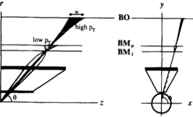
The first level (Ll ) muon trigger is based on fast, finely segmented, detectors to identify penetrating charged par- ticles pointing td the interaction region. The trigger is designed to unambiguously identify the interaction bunch crossing and to provide a sharp threshold over a large interval of transverse momentum. For the muon trigger system in the central toroid, IT,I) 5 1.05, RPCs are proposed for their good time resolution, ease in segmentation and low cost of production. The transverse momentum selec- tion is done with a fast coincidence between strips on different planes. The number of trigger planes is defined by the need to minimize the rate of accidental coincidences and to optimize the efficiency. To reduce the accidental rate to a level lower than the prompt muon rate, the trigger will operate in two projections, r-z and r-4. Thus the trigger detectors will also be used to provide the coordinate in the non-bending plane (r-4) to the muon tracking system. The different momentum selection criteria required by the relevant physics processes are best met using a low- and a high-p, trigger. This is implemented in the barrel as shown in Fig. 1. The trigger scheme uses three stations, two middle stations (BM), each made of two RPC planes and the outer station (BO), made of three RPC planes. The low-p, trigger requires a three-fold majority of the four
C. Bacci et al. I Nucl. Instr. and Meth. in Phys. Res. A 367 (1995) 428-431 429 r Y BO
BMo
BMi 3 x Fig. 1. Scheme of the first-level muon trigger in the barrel.middle planes while the high-p, trigger requires a two-fold majority of the three BO planes in coincidence with the low-p, trigger.
The size of the trigger window, to select muons with transverse momentum larger than pr is wbarre, =
alpp, sin ‘@, where ppr is the value of the transverse momentum after traversing the calorimeter. Fluctuations ih the energy loss and multiple scattering in the calorimeter, length of the interaction region and non-uniformity of the magnetic field are all smearing effects which make the choice of 3-4cm strip pitch a balanced choice between good selectivity and number of channels.
3. Detector description
Each RFC plane will be equipped with read-out strips on either side of the gas volume: z-strips parallel to the magnetic field and +-strips parallel to the beam. The operating mode has up to recent times limited its rate capability to lOOHz/cm*. Later tests have shown that its
Co Source ON I ,, Time resolution . Deloy . 0” 1 z .- .o iT, . &AA.. . . . 0.9 0.8 Co Source ON 10’ Flux {KHz/cm2) Flux (KHz/cm2)
performances improve substantially when operating the chamber in a lower gas amplification regime [2,3]. Here we present some recent results. The RPCs tested are single-gap chambers, built with bakelite plates (p = 4 X 10” fI cm) of 50 X 50 cm*. The signals are read out from two sets of orthogonal pickup strips of 1.5 cm pitch. The chambers have been operated with various mixtures of Freon 13Bl and n-butane. A 14 mCi 6oCo source was illuminating the detectors with a roughly uniform flux of 1.2 MeV photons producing an average rate of about 200 Hz/cm’. The RPC efficiency and time response was measured with muon and pion beams of 200 GeVlc, with fluxes up to -lOkHz/cm’. In Fig. 2 efficiency, time resolution and delay are shown as a function of the beam tlux. The time resolution is about 1 ns, and the response delay is smaller than 2 ns up to fluxes of 1 kHz/cm*, with an average efficiency of 20.97. These measurements prove that the detector operated in a low gain regime is adequate to the LHC needs.
4. Muon trigger processor
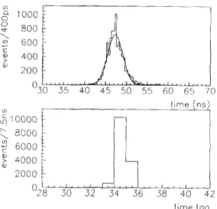
To be able to uniquely identify tracks belonging to a bunch crossing, it is not only necessary to have a fast detector, but the trigger electronics itself must have a time resolution comparable to the detector. Preliminary tests have been done with the RD5 experimental set-up [4]. Signals from two RPC planes were sent to a coincidence matrix built with very fast GaAs commercial components. The system used a 133 MHz frequency; the measured time resolution of the complete chain was well below 25 ns (see Fig. 3). An irreducible smearing of the resolution is due to the time propagation along the strips (5 nslm). In the final segmentation of the trigger we plan to use in the largest
Fig. 2. EFficiency, time resolution and delay of RPC operated at low gas gain.
430 C. Bocci et 01. J Nucl. Insir. and Meth. in Phys. Res. A 367 (1995) 428-431 l” : 10000 t 8000 2 6 6000 2 4000 2000 time (ns 30 32 34 36 38 40 L
12
time tog”
I
Fig. 3. Time resolution of the RD27 muon trigger demonstrator, measured with an eternal TDC and with an internal 133 MHz clock.
chambers 4 strips of AZ = 1 m, At < 3 ns and z-strips of length Ar4 = 2-3 m, At < 7 ns. The absolute trigger tim- ing will be defined by the shorter strips.
Some other constraints to the trigger design have to be considered before discussing implementation issues. First of all the trigger has to be multithreshold, allowing multimuon events to be selected with thresholds lower than the single muon ones. Six thresholds can be programmed in the range 5-35 GeVlc. All the previous needs are best met by developing an application specific integrated circuit.
4. I. The coincidence matrix
Our group has designed [5], in collaboration with the Rutherford Laboratory, a 0.5 pm CMOS 34k gate array for the front-end part of the trigger system. The demonstrator circuit contains two 8 X 24 coincidence matrices. The low- pT and high-p, algorithm can be implemented program- ming the same circuit for the two modes of operation. The detector signals, after discrimination, are fed into a mi- cropipeline running at a frequency multiple of 1 lT. This is done to compensate for different propagation times from different detector planes. The s or f majority algorithm is done in two steps; one part is common to all the columns or rows of the matrix (pre-process blocks), while the other has to be done cell by cell. The (most significant) hit pattern of the muon track(s) is fed into an output register, together with the threshold value the track(s) has (have) passed. The logic is distributed over an internal pipeline of maximum four steps length. Worst case simulations assure us that a maximum skew between different inputs to different outputs is below 1.8 ns, and maximum operating
frequency is above 100 MHz. The circuit is being built at the time of writing.
4.2. Trigger segmentation, ROIs
The trigger detectors in the barrel are segmented in 244 sectors: 16 between the coils (large sectors) and 8 close to the coils (small sectors). Along the z-axis the segmentation is projective to the interaction vertex. While the segmenta- tion of the detector itself comes mainly from the geometry of the experiment, the trigger has to suit other needs. The pT threshold coming from Ll will be refined at second level trigger (L2), by using the high precision chambers’ information. The Ll will provide Regions Of Interest (ROI), where the L2 processor will search for muon tracks in small sectors of the spectrometer. The L2 algorithm is initiated by the Ll strip information that has an average occupancy much smaller than the precision drift chamber and will be done within the desired latency of 2 l,~s. A good compromise between layout considerations and L2 needs is a segmentation AT X A+ - 0.25 X 0.10. In this case the barrel will be equipped with 1920 matrices of 32 x 64 strips.
4.3, Latency and timings
To evaluate the total latency of the system, local logic delay, cable delays and global logic have to be considered. The total delay is well below the 2 ps foreseen for the trigger latency. Due to the large area of the detector, timing is a critical issue; propagation time along different
regions of the detector, as well particles’ time of flight can
be longer than T. The foreseen Timing Control and Distribution System 161, by providing a reference 40 MHz clock and a programmable bunch crossing number, will be used as the starting point. Finer sub-period delays will be implemented using the micropipelines described above, for unique assignment of a track to a bunch crossing. A time interpolator running at 4/T or g/T frequency will be needed to monitor these delays,
I Y
Fig. 4. Scheme of ihe groups of strips connected to the co- incidence matrices.
C. Bacci et al. I Nucl. Instr. and Meth. in Phys. Res. A 367 (1995) 428-431 431
o4 1
/
b low Pt trigger 0.1 ! 00 I 5 10 15 20 25 30Fig. 5. Trigger acceptance as a function of pT.
4.4. Efficiency and rates
The trigger acceptance and rates have been evaluated with a detailed simulation of the layout. Fig. 5 shows the acceptance as a function of the muon J+ for a nominal
,
lb’
Lurninosity~ nb-‘s-’ 1 Lwninosit~,“nb-‘s-’
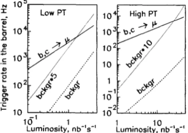
Fig. 6. Low and high-p, trigger rate in Iql< 1.05 as a function of the luminosity.
threshold of 6 GeV/c (20 GeVlc) of the low-p, (high-p,) trigger. Given the large area of the detector, an important contribution to the trigger rate can be due to accidental coincidences produced by low energy photons and neu- trons, The flux and the energy spectrum has been studied in detail in various shielding configurations [7]. The detector rate per unit area is derived convoluting the energy spectrum with the detector sensitivity [3]. Two sources of background contribute to the total trigger rate. The first contribution is due to accidental coincidences of uncorrelated hits on different trigger planes. The second source comes from charged particles (mostly electrons), that traverse two or more trigger planes. The trigger rate in the barrel is shown in Fig. 6 as a function of the luminosity for the low-p, and high-p, trigger configurations together with the rate of muons. The high level of coincidence and the intrinsic good time resolution of the detectors insure that the accidental coincidence rate is well below the prompt muon signal rate.
References [II 121 [31 [41 151 161 [71
ATLAS Technical Proposal, CERNILHCC/94-43, LHCC/P2 (15 December 1994).
G.L. Bencze et al., Nucl. Instr. and Meth. A 352 (1995) 552. L. Acitelli et al., Study of the efficiency and time resolution of a RPC irradiated with photons and neutrons, prep. 1039 Dipartimento di Fisica, Universid di Roma “La Sapienza” (15/7/ 1994).
G.L. Bencze et al., Nucl. Instr. and Meth. A 340 (1994) 466. J. Dowdell et al., A coincidence array demonstrator ASIC for the RD-27 muon trigger, RD-27 Note 30 (July 1994). B.G. Taylor, IEEE Nuclear Science Symp., San Francisco, 31/10-6111 1993.
G. Battistoni, A. Ferrari and P.R. Sala, Background calcula- tions for the ATLAS detector and hall, ATLAS note GEN- NO-010 (13.10.1994).