ScienceDirect
Available online at Available online at www.sciencedirect.comwww.sciencedirect.com
ScienceDirect
Structural Integrity Procedia 00 (2016) 000–000
www.elsevier.com/locate/procedia
2452-3216 © 2016 The Authors. Published by Elsevier B.V.
Peer-review under responsibility of the Scientific Committee of PCF 2016.
XV Portuguese Conference on Fracture, PCF 2016, 10-12 February 2016, Paço de Arcos, Portugal
Thermo-mechanical modeling of a high pressure turbine blade of an
airplane gas turbine engine
P. Brandão
a, V. Infante
b, A.M. Deus
c*
aDepartment of Mechanical Engineering, Instituto Superior Técnico, Universidade de Lisboa, Av. Rovisco Pais, 1, 1049-001 Lisboa,
Portugal
bIDMEC, Department of Mechanical Engineering, Instituto Superior Técnico, Universidade de Lisboa, Av. Rovisco Pais, 1, 1049-001 Lisboa,
Portugal
cCeFEMA, Department of Mechanical Engineering, Instituto Superior Técnico, Universidade de Lisboa, Av. Rovisco Pais, 1, 1049-001 Lisboa,
Portugal
Abstract
During their operation, modern aircraft engine components are subjected to increasingly demanding operating conditions, especially the high pressure turbine (HPT) blades. Such conditions cause these parts to undergo different types of time-dependent degradation, one of which is creep. A model using the finite element method (FEM) was developed, in order to be able to predict the creep behaviour of HPT blades. Flight data records (FDR) for a specific aircraft, provided by a commercial aviation company, were used to obtain thermal and mechanical data for three different flight cycles. In order to create the 3D model needed for the FEM analysis, a HPT blade scrap was scanned, and its chemical composition and material properties were obtained. The data that was gathered was fed into the FEM model and different simulations were run, first with a simplified 3D rectangular block shape, in order to better establish the model, and then with the real 3D mesh obtained from the blade scrap. The overall expected behaviour in terms of displacement was observed, in particular at the trailing edge of the blade. Therefore such a model can be useful in the goal of predicting turbine blade life, given a set of FDR data.
© 2016 The Authors. Published by Elsevier B.V.
Peer-review under responsibility of the Scientific Committee of PCF 2016.
Keywords: High Pressure Turbine Blade; Creep; Finite Element Method; 3D Model; Simulation.
* Corresponding author. Tel.: +351 218419991.
E-mail address: [email protected]
2452-3216 © 2016, PROSTR (Procedia Structural Integrity) Hosting by Elsevier Ltd. All rights reserved. Peer review under responsibility of the Scientific Committee of PCF 2016.
10.1016/j.prostr.2016.06.455
Procedia Structural Integrity 2 (2016) 3660–3667
© 2016, PROSTR (Procedia Structural Integrity) Hosting by Elsevier Ltd. All rights reserved. Peer-review under responsibility of the Scientific Committee of PCF 2016.
10.1016/j.prostr.2016.06.455
Available online at www.sciencedirect.com
ScienceDirect
Structural Integrity Procedia 00 (2016) 000–000
www.elsevier.com/locate/procedia
2452-3216 © 2016 The Authors. Published by Elsevier B.V.
Peer-review under responsibility of the Scientific Committee of ECF21.
21st European Conference on Fracture, ECF21, 20-24 June 2016, Catania, Italy
Assessment of Damage Evolution in Sandwich Composite Material
Subjected to Repeated Impacts by Means Optical Measurements
F. Cucinotta
a, E. Guglielmino
a, G. Risitano
a*, F. Sfravara
aa Department of Engineering, University of Messina, Contrada Di Dio (S. Agata), 98166 Messina, Italy
Abstract
In the last decade, sandwich composite materials have had an increasing use in design of racing boats. The main reasons are: higher strength-weight ratio, low density, excellent durability and versatility. The knowledge of impact response is very important to design racing boats.
The aim of the present study is the investigation of absorbing impact energy ability of a sandwich composite material used for offshore vessels in UIM (Unione Internationale Motonautique) Championship.
The material analysed in this study is a sandwich manufactured with hand lay-up technique. In the first phase, the damage assessment of single impact has been studied with an optical measurement technique. In a second phase, the damage evaluation due to repeated impacts has been analysed with the similar technique.
© 2016 The Authors. Published by Elsevier B.V.
Peer-review under responsibility of the Scientific Committee of ECF21.
Kywords: Low energy impact; Damage accumulation; Optical mesaurements; Lightweight composites; Nautical applications; Safety design. 1. Introduction
For many years, the sandwich composite materials have been used in a lot of engineering field. Mangalgiri (1999) reported a brief summary of applications in aeronautical field. From 1950 to our days, the use of sandwich composite material increased in automotive field; Mangino et al. (2007) reported this evolution. In the last decade, the naval
* Corresponding author. Tel.: +39-347-3209239; E-mail address: [email protected]
2 Author name / Structural Integrity Procedia 00 (2016) 000–000
engineering is focused on these materials; a brief review is reported by Mouritz et al. (2001). There are many advantages in the use of this type of material respect the traditional one; the principal ones have been reported by Gibson (2010): remarkable reduced weight compared to metals; high stiffness and strength respect to weight; reduced corrosion tendency. Furthermore, the composite material is therefore flexible to the needs of the designer. However, there are disadvantages, like a long-time durability low, heat resistance, sensitive with respect to the fabrication process, high material costs and open questions that concern recyclability and reparability.
An important aspect of sandwich composite materials is the mechanical behavior under different typologies of stresses. Studies evaluating the tensile resistance of fiber composite are reported by Rosen (1964). Another aspect is the flexural and torsional stiffness of sandwich composite materials; papers relative a these aspect are reported by Demakos (2003). It is necessary to know the resistance of the composite, but the collapse phase is very difficult to understand because there are several failure modes involved. Daniel et al. (2002) investigated the failure modes of sandwich beams. Budiansky and Fleck (1993) investigated the behavior of fiber composite materials under compression test. Important failure criteria have been developed in order to evaluate failure modes.
However, still many aspects need to be investigated. One example among many is the impact behavior of sandwich composite materials. Many papers use different approaches for evaluating the impact effects. The phenomenon can be described as the evolution of the first damage up to total failure when the material is not capable of supporting an additional load. Abrate (1998), Richardson and Wisheart (1996) investigated low velocity impact effects on the composite structures. Davies and Zhang (1995) proposed a new method to predict the internal damage on carbon fiber composite structures under low velocity impact. Belingardi and Vadori (2002) carried out low velocity impact tests on glass-fiber epoxy composite material. Gustin et al. (2005) showed the principal advantages of Kevlar plies respect to Carbon plies. Crupi et al. (2014) investigated the impact failure mode of different composite materials using compute tomography and IR camera. Hassan and Cantwell (2012) investigated the influence of core in the perforation phase on the sandwich composite materials. Atas and Sevim (2010) carried out a comparison between balsa-core and PVC-core on sandwich composite materials. Aktaş and Turan (2013) investigated the influence of plies of lamination. Sikarwar et al. (2014) investigated the impact effects on composite materials with different fiber-orientation. Liu (2004) proposed a new energy approach method to correlate the impact effect with damage process on composite laminates. Belingardi et al. (2007) proposed a new damage index to estimate the penetration in thick laminates.
In the last years, many researchers investigated the effects of repeated impacts on sandwich composite materials. Belingardi et al. (2008) examined the repeated impact effects on two similar composite materials (glass laminates) with different manufacturing technologies (hand lay-up and vacuum infusion).
The aim of this work is the investigation of absorbing impact energy ability of a sandwich composite material used for offshore vessels in UIM (Unione Internationale Motonautique) Championship. The material analysed in this study is a sandwich manufactured with hand lay-up technique. In the first phase, the damage assessment of single impact has been studied with an optical measurement technique. In a second phase, the damage evaluation due to repeated impacts has been analysed with the similar technique. For safety reason and design optimization, the repeated impact effects are very important to study on boats racing materials because the stresses caused are similar to the slamming stresses.
2. Material and methods
The tested material is a sandwich composite material made with the Hand Lay-Up technique. This manufacturing technique requires that the resin is processed through the use of catalysts and accelerators; thereafter, it is spread by hand on fabrics with rollers and paintbrushes. Table 1 shows mechanical characteristics and plies of lamination of the tested material. For the material tested, square-shaped samples (100 X 100 mm) with a thickness of 26 mm have been obtained (Figure 1). The machine used to carry out impact test is the CEAST Fractovis Plus. The impact energy has been managed by the height variation of the grave and through the impact speed. The indenter used has a hemispherical shape with a diameter equal to 20 mm.
F. Cucinotta et al. / Procedia Structural Integrity 2 (2016) 3660–3667 3661
ScienceDirect
Structural Integrity Procedia 00 (2016) 000–000
www.elsevier.com/locate/procedia
2452-3216 © 2016 The Authors. Published by Elsevier B.V.
Peer-review under responsibility of the Scientific Committee of ECF21.
21st European Conference on Fracture, ECF21, 20-24 June 2016, Catania, Italy
Assessment of Damage Evolution in Sandwich Composite Material
Subjected to Repeated Impacts by Means Optical Measurements
F. Cucinotta
a, E. Guglielmino
a, G. Risitano
a*, F. Sfravara
aa Department of Engineering, University of Messina, Contrada Di Dio (S. Agata), 98166 Messina, Italy
Abstract
In the last decade, sandwich composite materials have had an increasing use in design of racing boats. The main reasons are: higher strength-weight ratio, low density, excellent durability and versatility. The knowledge of impact response is very important to design racing boats.
The aim of the present study is the investigation of absorbing impact energy ability of a sandwich composite material used for offshore vessels in UIM (Unione Internationale Motonautique) Championship.
The material analysed in this study is a sandwich manufactured with hand lay-up technique. In the first phase, the damage assessment of single impact has been studied with an optical measurement technique. In a second phase, the damage evaluation due to repeated impacts has been analysed with the similar technique.
© 2016 The Authors. Published by Elsevier B.V.
Peer-review under responsibility of the Scientific Committee of ECF21.
Kywords: Low energy impact; Damage accumulation; Optical mesaurements; Lightweight composites; Nautical applications; Safety design. 1. Introduction
For many years, the sandwich composite materials have been used in a lot of engineering field. Mangalgiri (1999) reported a brief summary of applications in aeronautical field. From 1950 to our days, the use of sandwich composite material increased in automotive field; Mangino et al. (2007) reported this evolution. In the last decade, the naval
* Corresponding author. Tel.: +39-347-3209239; E-mail address: [email protected]
2 Author name / Structural Integrity Procedia 00 (2016) 000–000
engineering is focused on these materials; a brief review is reported by Mouritz et al. (2001). There are many advantages in the use of this type of material respect the traditional one; the principal ones have been reported by Gibson (2010): remarkable reduced weight compared to metals; high stiffness and strength respect to weight; reduced corrosion tendency. Furthermore, the composite material is therefore flexible to the needs of the designer. However, there are disadvantages, like a long-time durability low, heat resistance, sensitive with respect to the fabrication process, high material costs and open questions that concern recyclability and reparability.
An important aspect of sandwich composite materials is the mechanical behavior under different typologies of stresses. Studies evaluating the tensile resistance of fiber composite are reported by Rosen (1964). Another aspect is the flexural and torsional stiffness of sandwich composite materials; papers relative a these aspect are reported by Demakos (2003). It is necessary to know the resistance of the composite, but the collapse phase is very difficult to understand because there are several failure modes involved. Daniel et al. (2002) investigated the failure modes of sandwich beams. Budiansky and Fleck (1993) investigated the behavior of fiber composite materials under compression test. Important failure criteria have been developed in order to evaluate failure modes.
However, still many aspects need to be investigated. One example among many is the impact behavior of sandwich composite materials. Many papers use different approaches for evaluating the impact effects. The phenomenon can be described as the evolution of the first damage up to total failure when the material is not capable of supporting an additional load. Abrate (1998), Richardson and Wisheart (1996) investigated low velocity impact effects on the composite structures. Davies and Zhang (1995) proposed a new method to predict the internal damage on carbon fiber composite structures under low velocity impact. Belingardi and Vadori (2002) carried out low velocity impact tests on glass-fiber epoxy composite material. Gustin et al. (2005) showed the principal advantages of Kevlar plies respect to Carbon plies. Crupi et al. (2014) investigated the impact failure mode of different composite materials using compute tomography and IR camera. Hassan and Cantwell (2012) investigated the influence of core in the perforation phase on the sandwich composite materials. Atas and Sevim (2010) carried out a comparison between balsa-core and PVC-core on sandwich composite materials. Aktaş and Turan (2013) investigated the influence of plies of lamination. Sikarwar et al. (2014) investigated the impact effects on composite materials with different fiber-orientation. Liu (2004) proposed a new energy approach method to correlate the impact effect with damage process on composite laminates. Belingardi et al. (2007) proposed a new damage index to estimate the penetration in thick laminates.
In the last years, many researchers investigated the effects of repeated impacts on sandwich composite materials. Belingardi et al. (2008) examined the repeated impact effects on two similar composite materials (glass laminates) with different manufacturing technologies (hand lay-up and vacuum infusion).
The aim of this work is the investigation of absorbing impact energy ability of a sandwich composite material used for offshore vessels in UIM (Unione Internationale Motonautique) Championship. The material analysed in this study is a sandwich manufactured with hand lay-up technique. In the first phase, the damage assessment of single impact has been studied with an optical measurement technique. In a second phase, the damage evaluation due to repeated impacts has been analysed with the similar technique. For safety reason and design optimization, the repeated impact effects are very important to study on boats racing materials because the stresses caused are similar to the slamming stresses.
2. Material and methods
The tested material is a sandwich composite material made with the Hand Lay-Up technique. This manufacturing technique requires that the resin is processed through the use of catalysts and accelerators; thereafter, it is spread by hand on fabrics with rollers and paintbrushes. Table 1 shows mechanical characteristics and plies of lamination of the tested material. For the material tested, square-shaped samples (100 X 100 mm) with a thickness of 26 mm have been obtained (Figure 1). The machine used to carry out impact test is the CEAST Fractovis Plus. The impact energy has been managed by the height variation of the grave and through the impact speed. The indenter used has a hemispherical shape with a diameter equal to 20 mm.
3662 Author name / Structural Integrity Procedia 00 (2016) 000–000 F. Cucinotta et al. / Procedia Structural Integrity 2 (2016) 3660–3667 3
Table 1 - Mechanical characteristics
Plies of lamination - Panel A & B
Ply Material Orientation Weight [gr/m2]
1 E-Glass MAT Random 300 o 450
2 Carbon 45/45 407 3 Carbon 0/45/90/45 807 4 Carbon 45/45 407 5 CoreCell 20 mm 6 Carbon 45/45 407 7 Carbon 0/45/90/45 807 8 Carbon 45/45 407 9 Kevlar - 175
The first phase of the work is the evaluation of the single impact effects to estimate the energy perforation limit. The energy levels are 13 J, 15.5 J, 18 J, 38 J and 59 J. The second phase of the work is the evaluation of repeated impact effects until to perforation. The energy levels used are only 13 J, 15.5 J and 18 J. After every single impact, estimation of mark size has been obtained by ATOS-3D Scan of GOM system. Figure 2 shows the clamping apparatus, specifically designed in order to assure the perforation always at the same point. Atos scan possesses a structured blue-light projector and two cameras which performing accurate scans with detailed resolution (in the order of hundredths of millimetre) at high speed. The triangulation method has been used to produce a cloud of points of the component surface and a full surface geometry has been obtained used a polygon mesh process (Figure 3).
After the polygonal mesh process, a post-processing reconstruction process has been done by a CAD-Software. During actual stage, the precision of reconstruction is important; an accurate deviation analysis between the mesh surface and the reconstructed CAD-Surface has been done. The reconstructed surface has been obtained by a loft procedure. For each curve has been analysed the better way to reduce deviation from the mesh. Figure 4 shows an example: the initial maximum deviation of curve respect to mesh is 0.177 mm (left image) and with a manual manipulation is reduced to 0.0211mm (right image).
Figure 3- Polygonal mesh
1cm
Figure 2- The specimen inside the clamping system. It is possible to note the markers for the 3D scanner
Figure 1 - The sandwich specimen
4 Author name / Structural Integrity Procedia 00 (2016) 000–000
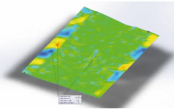
After the reconstruction of the CAD-Surface, a deviation analysis has been performed (deviation average is about thousandth of a millimetre -Figure 5). It is possible to have the volume of indenter impression after each single impact by CAD-reconstruction (Figure 6).
3. Results and discussion 3.1. Single impact tests
Three specimens have been tested for each energy level (13J, 15.5J, 18J, 38J and 59J). Figure 7 shows the Force vs Displacement curves at each levels of impact energy tested. As will be seen below, a lot of parameter has been extrapolated by these curves. The curves are superimposable until the impact energy is completely transferred to the sandwich (beginning of the oscillations). The area subtended by this curve is the absorbed energy of sandwich for internal and external damage. This area is larger with the increase of energy. The rebound of the indenter is great for small impact energies. The rebound of the indenter becomes minimum when the energies of impact are large and the total energy is absorbed to generate a visible and permanent damage.
Figure 4 – Section curves on polygonal mesh with analysis of deviation
Table 1 - Mechanical characteristics
Plies of lamination - Panel A & B
Ply Material Orientation Weight [gr/m2]
1 E-Glass MAT Random 300 o 450
2 Carbon 45/45 407 3 Carbon 0/45/90/45 807 4 Carbon 45/45 407 5 CoreCell 20 mm 6 Carbon 45/45 407 7 Carbon 0/45/90/45 807 8 Carbon 45/45 407 9 Kevlar - 175
The first phase of the work is the evaluation of the single impact effects to estimate the energy perforation limit. The energy levels are 13 J, 15.5 J, 18 J, 38 J and 59 J. The second phase of the work is the evaluation of repeated impact effects until to perforation. The energy levels used are only 13 J, 15.5 J and 18 J. After every single impact, estimation of mark size has been obtained by ATOS-3D Scan of GOM system. Figure 2 shows the clamping apparatus, specifically designed in order to assure the perforation always at the same point. Atos scan possesses a structured blue-light projector and two cameras which performing accurate scans with detailed resolution (in the order of hundredths of millimetre) at high speed. The triangulation method has been used to produce a cloud of points of the component surface and a full surface geometry has been obtained used a polygon mesh process (Figure 3).
After the polygonal mesh process, a post-processing reconstruction process has been done by a CAD-Software. During actual stage, the precision of reconstruction is important; an accurate deviation analysis between the mesh surface and the reconstructed CAD-Surface has been done. The reconstructed surface has been obtained by a loft procedure. For each curve has been analysed the better way to reduce deviation from the mesh. Figure 4 shows an example: the initial maximum deviation of curve respect to mesh is 0.177 mm (left image) and with a manual manipulation is reduced to 0.0211mm (right image).
Figure 3- Polygonal mesh
1cm
Figure 2- The specimen inside the clamping system. It is possible to note the markers for the 3D scanner
Figure 1 - The sandwich specimen
After the reconstruction of the CAD-Surface, a deviation analysis has been performed (deviation average is about thousandth of a millimetre -Figure 5). It is possible to have the volume of indenter impression after each single impact by CAD-reconstruction (Figure 6).
3. Results and discussion 3.1. Single impact tests
Three specimens have been tested for each energy level (13J, 15.5J, 18J, 38J and 59J). Figure 7 shows the Force vs Displacement curves at each levels of impact energy tested. As will be seen below, a lot of parameter has been extrapolated by these curves. The curves are superimposable until the impact energy is completely transferred to the sandwich (beginning of the oscillations). The area subtended by this curve is the absorbed energy of sandwich for internal and external damage. This area is larger with the increase of energy. The rebound of the indenter is great for small impact energies. The rebound of the indenter becomes minimum when the energies of impact are large and the total energy is absorbed to generate a visible and permanent damage.
Figure 4 – Section curves on polygonal mesh with analysis of deviation
3664 Author name / Structural Integrity Procedia 00 (2016) 000–000 F. Cucinotta et al. / Procedia Structural Integrity 2 (2016) 3660–3667 5
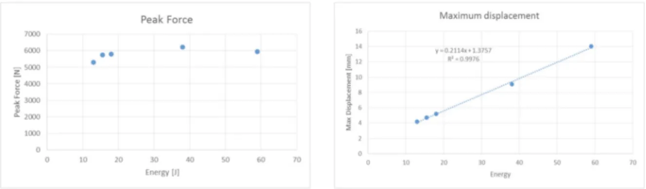
Figure 8 (a) shows Peak Force versus Energy and Figure 8 (b) shows Maximum Displacement versus Energy. A first important parameter is the maximum load capacity (Peak Force) of the material. In this case, it has a constant value because it depends on the material (material that is the same for all the impact tests). A second parameter is the Maximum Displacement. It corresponds to the indenter maximum penetration on the material taking into account both elastic phase that plastic. The experimental values follow a linear regression with a good approximation. .
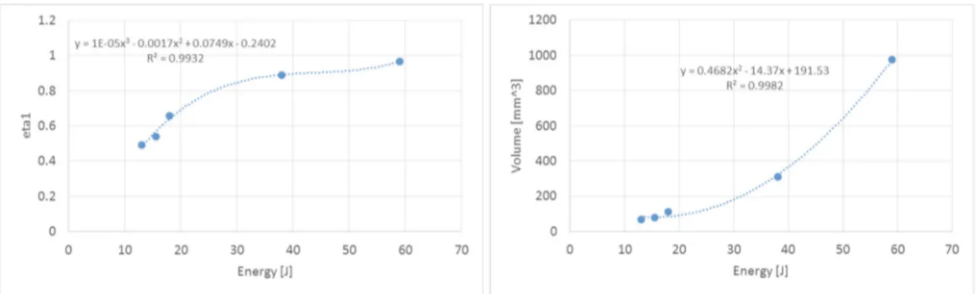
The third parameter is the Damage Degree. It is the ratio of energy absorbed by the material and the energy provided by the impact machine. The absorbed energy is calculated as the integral of the force on the displacement. The Damage Degree is a very important value because when this rapport is equal to 1 then the material has absorbed the entire amount of energy provided by the machine and, therefore, a perforation is present on the specimen. A cubic polynomial law fits the experimental values as shown in Figure 9 (a) and reported by Belingardi and Vadori (2002). The visible impact damage on the specimen has been evaluated by a scanner 3D. The volume of the indenter impress due to the plastic deformation has been investigated. Figure 9 (b)Errore. L'origine riferimento non è stata trovata.
shows the volume of indenter impress at each energy level. The experimental volume increase is well fitted by a parabolic curves.
Figure 8 - Peak Force vs Energy (a) - Max displacement vs energy (b) Figure 7 - Characteristic curves of an impact test
6 Author name / Structural Integrity Procedia 00 (2016) 000–000
3.2. Repeated impact tests
Repeated impact stage has been conducted at constant impact energy level until the upper skin. A specific clamping system has been designed by the writers in order to ensure the repeated impacts in the same point. More specimens have been tested for each impact level in order to verify the results repeatability. Figure 10 (a) shows the average value of Peak Forces versus the repeated impact number. Standard deviations and relative regression curves (e.g. linear, polynomial or exponential) has been showed. It is possible to note that the matching regression curve is well done for all plots. The value of the slope at the origin of the force-displacement curve is the stiffness (Figure 10 b). The stiffness is not significantly influenced by the impact energy. In the first impact, Peak Force is constant for each energy level (Figure 10 a).
The low standard deviation is a good estimation of repeatability of the tests. The Impress Volumes, detected by the 3D scan, grow in a linear way with the number of impacts. Although, there is a medium standard deviation.
y = ‐20,119x2+ 63,101x + 5394,8 R² = 0,9719 y = ‐42,33x2+ 86,54x + 5686,2 R² = 0,9936 y = ‐82,039x2+ 24,03x + 5898,7 R² = 0,9833 0 1000 2000 3000 4000 5000 6000 7000 0 5 10 15 Impact number
Peak Forces [N]
13J 15.5J 18J y = 2183,8x‐1,095 R² = 0,9304 y = 1628,4x‐0,866 R² = 0,9858 y = 1477,5x‐1,01 R² = 0,994 0 500 1000 1500 2000 2500 0 5 10 15 Impact numberStiffness [N/mm]
13J 15.5J 18JFigure 9 – Damage Degree vs Energy (a) - Volume vs Energy (b)
Figure 8 (a) shows Peak Force versus Energy and Figure 8 (b) shows Maximum Displacement versus Energy. A first important parameter is the maximum load capacity (Peak Force) of the material. In this case, it has a constant value because it depends on the material (material that is the same for all the impact tests). A second parameter is the Maximum Displacement. It corresponds to the indenter maximum penetration on the material taking into account both elastic phase that plastic. The experimental values follow a linear regression with a good approximation. .
The third parameter is the Damage Degree. It is the ratio of energy absorbed by the material and the energy provided by the impact machine. The absorbed energy is calculated as the integral of the force on the displacement. The Damage Degree is a very important value because when this rapport is equal to 1 then the material has absorbed the entire amount of energy provided by the machine and, therefore, a perforation is present on the specimen. A cubic polynomial law fits the experimental values as shown in Figure 9 (a) and reported by Belingardi and Vadori (2002). The visible impact damage on the specimen has been evaluated by a scanner 3D. The volume of the indenter impress due to the plastic deformation has been investigated. Figure 9 (b)Errore. L'origine riferimento non è stata trovata.
shows the volume of indenter impress at each energy level. The experimental volume increase is well fitted by a parabolic curves.
Figure 8 - Peak Force vs Energy (a) - Max displacement vs energy (b)
Figure 7 - Characteristic curves of an impact test 3.2. Repeated impact tests
Repeated impact stage has been conducted at constant impact energy level until the upper skin. A specific clamping system has been designed by the writers in order to ensure the repeated impacts in the same point. More specimens have been tested for each impact level in order to verify the results repeatability. Figure 10 (a) shows the average value of Peak Forces versus the repeated impact number. Standard deviations and relative regression curves (e.g. linear, polynomial or exponential) has been showed. It is possible to note that the matching regression curve is well done for all plots. The value of the slope at the origin of the force-displacement curve is the stiffness (Figure 10 b). The stiffness is not significantly influenced by the impact energy. In the first impact, Peak Force is constant for each energy level (Figure 10 a).
The low standard deviation is a good estimation of repeatability of the tests. The Impress Volumes, detected by the 3D scan, grow in a linear way with the number of impacts. Although, there is a medium standard deviation.
y = ‐20,119x2+ 63,101x + 5394,8 R² = 0,9719 y = ‐42,33x2+ 86,54x + 5686,2 R² = 0,9936 y = ‐82,039x2+ 24,03x + 5898,7 R² = 0,9833 0 1000 2000 3000 4000 5000 6000 7000 0 5 10 15 Impact number
Peak Forces [N]
13J 15.5J 18J y = 2183,8x‐1,095 R² = 0,9304 y = 1628,4x‐0,866 R² = 0,9858 y = 1477,5x‐1,01 R² = 0,994 0 500 1000 1500 2000 2500 0 5 10 15 Impact numberStiffness [N/mm]
13J 15.5J 18JFigure 9 – Damage Degree vs Energy (a) - Volume vs Energy (b)
3666 Author name / Structural Integrity Procedia 00 (2016) 000–000 F. Cucinotta et al. / Procedia Structural Integrity 2 (2016) 3660–3667 7
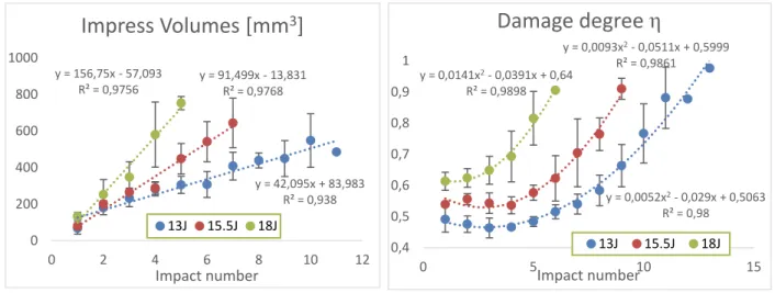
It is interesting to note that the linear trend of the Impress Volumes is different respect to trend of the absorbed energies represented by the mean of the Damage degree η, defined as the ratio between absorbed energy and impacting energy (Figure 11 a and b). This can be explained because the samples are sandwich composites laminates. Therefore, the absorbing energy capability is not proportional to the impact number, unlike the Impress Volume.
4. Conclusions
Repeated impacts tests at constant energy are conducted to analyse the damage evolution in sandwich composites. Samples are hand lay-up sandwich with carbon fiber plies (biaxial and quadriaxial) and PVC core, designed for
X-CAT class of UIM. A made home clamping apparatus ensures that each impact is exactly over the previous. The impress plastic volume of each impact has been detected by a 3D scanning.
The following reports summarize the experimental results: The tests have a good repeatability.
The single impact tests varying the impacting energy show that the absorbed energy follows a cubic trend. There is an exponential decay of the stiffness and a reduction of the peak force (parabolic law) to grow the
impacts number.
The absorbed energy grows in parabolic way.
The detected impress volumes grow linearly with impacting energy. The optical measurement is an good tool to estimate impact effects.
The correlation between detected volumes and absorbed energy is not linear.
Acknowledgements
Authors wish to thanks the Union International Motonautique for the providing of the samples and Mr. Sergio Abrami for the precious comments and suggestions.
y = 42,095x + 83,983 R² = 0,938 y = 91,499x ‐ 13,831 R² = 0,9768 y = 156,75x ‐ 57,093 R² = 0,9756 0 200 400 600 800 1000 0 2 4 6 8 10 12 Impact number
Impress Volumes [mm
3]
13J 15.5J 18J y = 0,0052x2‐ 0,029x + 0,5063 R² = 0,98 y = 0,0093x2‐ 0,0511x + 0,5999 R² = 0,9861 y = 0,0141x2‐ 0,0391x + 0,64 R² = 0,9898 0,4 0,5 0,6 0,7 0,8 0,9 1 0 5Impact number10 15Damage degree η
13J 15.5J 18JFigure 11 – Impress Volume vs Impact number (a) – Damage degree vs Impact number (b)
8 Author name / Structural Integrity Procedia 00 (2016) 000–000 References
Abrate, S. 1998. Impact Engineering of Composite Structures. Edited by Cambridge University Press. Cambridge.
Aktaş, Alaattin, Mehmet Aktaş, Fatih Turan. 2013. The Effect of Stacking Sequence on the Impact and Post-Impact Behavior of Woven/knit Fabric Glass/epoxy Hybrid Composites. Composite Structures 103, 119–35.
Atas, Cesim, Cenk Sevim. 2010. On the Impact Response of Sandwich Composites with Cores of Balsa Wood and PVC Foam. Composite Structures 93 (1). Elsevier Ltd, 40–48.
Belingardi, Giovanni, Maria Pia Cavatorta, Davide Salvatore Paolino. 2007. Repeated Impact Response of Hand Lay-up and Vacuum Infusion Thick Glass Reinforced Laminates. International Journal of Impact Engineering 35, 609–19.
Belingardi, Giovanni, Roberto Vadori. 2002. Low Velocity Impact Tests of Laminate Glass-Fiber-Epoxy Matrix Composite Material Plates. International Journal of Impact Engineering 27 (2), 213–29.
Budiansky, B., N.A. Fleck. 1993. Compressive Failure of Fibre Composites. Journal of the Mechanics and Physics of Solids 41 (1), 183–211. Crupi, V., G. Epasto, E. Guglielmino. 2014. Internal Damage Investigation of Composites Subjected to Low-Velocity Impact. Experimental
Techniques.
Daniel, I. M., E. E. Gdoutos, K.-A. Wang, J. L. Abot. 2002. Failure Modes of Composite Sandwich Beams. International Journal of Damage Mechanics 11 (4), 309–34.
Davies, G.a.O., X. Zhang. 1995. Impact Damage Prediction in Carbon Composite Structures. International Journal of Impact Engineering 16 (1), 149–70.
Demakos, C B. 2003. Stress Fields in Fiber Reinforced Laminate Beams Due to Bending and Torsion Moments. Journal of Reinforced Plastics and Composites 22 (5), 399–418.
Gibson, Ronald F. 2010. A Review of Recent Research on Mechanics of Multifunctional Composite Materials and Structures. Composite Structures 92 (12), 2793–2810.
Gustin, Jeremy, Aaran Joneson, Mohammad Mahinfalah, James Stone. 2005. Low Velocity Impact of Combination Kevlar/carbon Fiber Sandwich Composites. Composite Structures 69 (4), 396–406.
Hassan, M. Z., W. J. Cantwell. 2012. The Influence of Core Properties on the Perforation Resistance of Sandwich Structures - An Experimental Study. Composites Part B: Engineering 43 (8). Elsevier Ltd, 3231–38.
Liu, D. 2004. Characterization of Impact Properties and Damage Process of Glass/Epoxy Composite Laminates. Journal of Composite Materials 38 (16), 1425–42.
Mangalgiri, P D. 1999. Composite Materials for Aerospace Applications. Bulletin of Materials Science 22 (3), 657–64.
Mangino, Enrico, Joe Carruthers, Giuseppe Pitarresi. 2007. The Future Use of Structural Composite Materials in the Automotive Industry. International Journal of Vehicle Design 44 (3/4), 211.
Richardson, M. O W, M. J. Wisheart. 1996. Review of Low-Velocity Impact Properties of Composite Materials. Composites Part A: Applied Science and Manufacturing 27 (12 PART A), 1123–33.
ROSEN, B. W. 1964. Tensile Failure of Fibrous Composites. AIAA Journal 2 (11), 1985–91.
Sikarwar, Rahul S., R. Velmurugan, N. K. Gupta. 2014. Influence of Fiber Orientation and Thickness on the Response of Glass/epoxy Composites Subjected to Impact Loading. Composites Part B, Engineering 60. Elsevier Ltd, 627–36.
It is interesting to note that the linear trend of the Impress Volumes is different respect to trend of the absorbed energies represented by the mean of the Damage degree η, defined as the ratio between absorbed energy and impacting energy (Figure 11 a and b). This can be explained because the samples are sandwich composites laminates. Therefore, the absorbing energy capability is not proportional to the impact number, unlike the Impress Volume.
4. Conclusions
Repeated impacts tests at constant energy are conducted to analyse the damage evolution in sandwich composites. Samples are hand lay-up sandwich with carbon fiber plies (biaxial and quadriaxial) and PVC core, designed for
X-CAT class of UIM. A made home clamping apparatus ensures that each impact is exactly over the previous. The impress plastic volume of each impact has been detected by a 3D scanning.
The following reports summarize the experimental results: The tests have a good repeatability.
The single impact tests varying the impacting energy show that the absorbed energy follows a cubic trend. There is an exponential decay of the stiffness and a reduction of the peak force (parabolic law) to grow the
impacts number.
The absorbed energy grows in parabolic way.
The detected impress volumes grow linearly with impacting energy. The optical measurement is an good tool to estimate impact effects.
The correlation between detected volumes and absorbed energy is not linear.
Acknowledgements
Authors wish to thanks the Union International Motonautique for the providing of the samples and Mr. Sergio Abrami for the precious comments and suggestions.
y = 42,095x + 83,983 R² = 0,938 y = 91,499x ‐ 13,831 R² = 0,9768 y = 156,75x ‐ 57,093 R² = 0,9756 0 200 400 600 800 1000 0 2 4 6 8 10 12 Impact number
Impress Volumes [mm
3]
13J 15.5J 18J y = 0,0052x2‐ 0,029x + 0,5063 R² = 0,98 y = 0,0093x2‐ 0,0511x + 0,5999 R² = 0,9861 y = 0,0141x2‐ 0,0391x + 0,64 R² = 0,9898 0,4 0,5 0,6 0,7 0,8 0,9 1 0 5Impact number10 15Damage degree η
13J 15.5J 18JFigure 11 – Impress Volume vs Impact number (a) – Damage degree vs Impact number (b)
References
Abrate, S. 1998. Impact Engineering of Composite Structures. Edited by Cambridge University Press. Cambridge.
Aktaş, Alaattin, Mehmet Aktaş, Fatih Turan. 2013. The Effect of Stacking Sequence on the Impact and Post-Impact Behavior of Woven/knit Fabric Glass/epoxy Hybrid Composites. Composite Structures 103, 119–35.
Atas, Cesim, Cenk Sevim. 2010. On the Impact Response of Sandwich Composites with Cores of Balsa Wood and PVC Foam. Composite Structures 93 (1). Elsevier Ltd, 40–48.
Belingardi, Giovanni, Maria Pia Cavatorta, Davide Salvatore Paolino. 2007. Repeated Impact Response of Hand Lay-up and Vacuum Infusion Thick Glass Reinforced Laminates. International Journal of Impact Engineering 35, 609–19.
Belingardi, Giovanni, Roberto Vadori. 2002. Low Velocity Impact Tests of Laminate Glass-Fiber-Epoxy Matrix Composite Material Plates. International Journal of Impact Engineering 27 (2), 213–29.
Budiansky, B., N.A. Fleck. 1993. Compressive Failure of Fibre Composites. Journal of the Mechanics and Physics of Solids 41 (1), 183–211. Crupi, V., G. Epasto, E. Guglielmino. 2014. Internal Damage Investigation of Composites Subjected to Low-Velocity Impact. Experimental
Techniques.
Daniel, I. M., E. E. Gdoutos, K.-A. Wang, J. L. Abot. 2002. Failure Modes of Composite Sandwich Beams. International Journal of Damage Mechanics 11 (4), 309–34.
Davies, G.a.O., X. Zhang. 1995. Impact Damage Prediction in Carbon Composite Structures. International Journal of Impact Engineering 16 (1), 149–70.
Demakos, C B. 2003. Stress Fields in Fiber Reinforced Laminate Beams Due to Bending and Torsion Moments. Journal of Reinforced Plastics and Composites 22 (5), 399–418.
Gibson, Ronald F. 2010. A Review of Recent Research on Mechanics of Multifunctional Composite Materials and Structures. Composite Structures 92 (12), 2793–2810.
Gustin, Jeremy, Aaran Joneson, Mohammad Mahinfalah, James Stone. 2005. Low Velocity Impact of Combination Kevlar/carbon Fiber Sandwich Composites. Composite Structures 69 (4), 396–406.
Hassan, M. Z., W. J. Cantwell. 2012. The Influence of Core Properties on the Perforation Resistance of Sandwich Structures - An Experimental Study. Composites Part B: Engineering 43 (8). Elsevier Ltd, 3231–38.
Liu, D. 2004. Characterization of Impact Properties and Damage Process of Glass/Epoxy Composite Laminates. Journal of Composite Materials 38 (16), 1425–42.
Mangalgiri, P D. 1999. Composite Materials for Aerospace Applications. Bulletin of Materials Science 22 (3), 657–64.
Mangino, Enrico, Joe Carruthers, Giuseppe Pitarresi. 2007. The Future Use of Structural Composite Materials in the Automotive Industry. International Journal of Vehicle Design 44 (3/4), 211.
Richardson, M. O W, M. J. Wisheart. 1996. Review of Low-Velocity Impact Properties of Composite Materials. Composites Part A: Applied Science and Manufacturing 27 (12 PART A), 1123–33.
ROSEN, B. W. 1964. Tensile Failure of Fibrous Composites. AIAA Journal 2 (11), 1985–91.
Sikarwar, Rahul S., R. Velmurugan, N. K. Gupta. 2014. Influence of Fiber Orientation and Thickness on the Response of Glass/epoxy Composites Subjected to Impact Loading. Composites Part B, Engineering 60. Elsevier Ltd, 627–36.