Abstract— We present the theoretical analysis and the numerical simulations of a polarization-independent coherent receiver for binary Intensity-Modulated (IM) signals. The receiver is designed for access networks or data centers and is DSP-free. It is based on a 3x3 symmetric coupler with phase-diversity detection. To achieve polarization independence, the receiver conveniently exploits the third input of the 3x3 coupler, which was previously left unused. We first introduce the scheme of the receiver and derive the analytical expressions for the final output signal, which is produced by analog processing. We then confirm the approach by numerical simulations. These are used to assess the practical potential and indicate the possible limitations. We finally discuss the role of the key parameters that must be considered in upgrading to higher bit rates and the extension to other modulation formats.
Index Terms-- Fiber optic communication, bit error ratio (BER), coherent systems, polarization.
I. INTRODUCTION
T
HE exponential growth of bandwidth request for different applications and the future demands of 5G are driving the evolution of the access network. In the near future, these networks will have to provide high data-rate connections to end users (both residential/business and base-stations) at limited cost [1]. Currently, operators are still deploying PON (Passive Optical Network) solutions, although they are quickly moving to WDM-PON (WDM: Wavelength Division Multiplexing) [2]. Clearly, for the seamless evolution of access networks the infrastructure already in place must be left untouched; thus, any upgrade should be carried out by simply changing the hardware at Optical Line Terminal (OLT) and Optical Network Unit (ONU). Yet, current infrastructures are based on power-splitters, which have high insertion loss and thus ask for very high power-budget. When upgrades are required, it is hard to achieve compatibility with these high-loss networks, mostly because the systems with higher bit rates typically have much worse sensitivity [3]. Similar motivations are raised for data-centers, where low-cost coherent solutions are actively investigated, possibly without DSP.To address the sensitivity issue, coherent detection was proposed, as it can provide higher sensitivity [4]. Coherent systems are currently deployed in the core and metro networks,
Manuscript received xxx.
E. Ciaramella is with Scuola Superiore Sant’Anna, Istituto di Tecnologie della Comunicazione, dell’Informazione e della Percezione (TeCIP), 56127 Pisa, Italy (e-mail: [email protected]).
but the cost levels typical of optical access networks are completely different: here the end-users cannot simply afford costly solutions, i.e. based on expensive optical and/or electronical devices, such as the ones used in core networks. To this aim, the project COCONUT addressed the feasibility of coherent systems designed to meet the target requirements of mass deployment, i.e. low cost at high volumes [5]. Among the first achievements, a 1.25 Gbit/s coherent receiver (RX) based on phase-diversity envelope detection [6] was realized using simple processing, a symmetric fiber coupler and a DFB laser as local oscillator (LO); although realized with common devices, it achieved high sensitivity without DSP [7]. However, its key limitation was its polarization-dependency.
Coherent RXs often achieve polarization independency by polarization diversity [8], [9]. Alternatively, polarization scrambling at the transmitter [10] or an endless polarization controller at the RX might be chosen [11]. In all above cases, the hardware and/or the signal processing heavily increase, thus making the coherent system hardly suitable for access networks. In order to fit the access requirements, we therefore introduced a novel concept to achieve Polarization-Independence (PI): it uses exactly the same structure as in a phase-diversity RX based on a symmetric 3:3 coupler and exploits for the first time the unused third input of the coupler [12]. Later on, the scheme was experimentally demonstrated; it was proved to work in real-time at 1 Gbit/s, [13] and then tested by offline processing at 10 Gbit/s also with Direct Modulated Laser (DML) [13].
As only a preliminary theoretical evidence of the PI was presented in [12], here we present the complete analysis and theoretical assessment of the PI-RX. We fully analyze the RX by analytical equations and provide detailed insight of the Bit Error Ratio (BER) performance by means of Monte Carlo simulations. We present the analytical expression of the generic currents at the photodiode outputs and then derive the variation of the signal quality as a function of the input state of polarization (SoP). We then estimate the performance of the PI-RX by numerical simulations and evaluate the sensitivity as function of the SoP parameters for an ideal RX. We then analyze the residual SoP-dependence of the receiver. We also test numerically the PI-RX robustness to different implementation issues (such as delays, unbalance of the coupler, RIN of the LO etc.). Finally, we assess the extension to duobinary format.
E. Ciaramella, Senior Member, IEEE
Assessment of a Polarization-Independent DSP-Free
Coherent Receiver for Intensity-Modulated Signals
II. OPERATION PRINCIPLE
In this section we describe the modifications of the polarization-sensitive RX proposed in [6] that allow to achieve PI by exploiting the third, unused input of the 3x3 coupler. To this aim, we can introduce different combinations and those can help defining a class of similar receivers that attain a very good polarization insensitivity.
For the sake of clarity, we present in Fig. 1 the two main schemes for the proposed RX, which will be also analyzed theoretically. In the first case, the IM signal enters one of the inputs of the 3x3 coupler with random SoP; the LO enters at
/4 a polarization beam splitter (PBS), is split into two orthogonal components, which have thus the same amplitude, and these finally enter the 3x3 coupler. For simplicity, the connections between the PBS and the coupler are assumed not to change the SoP of the lightwaves. In the second case, the input signal is split by a PBS, its two orthogonal components are separated, the 2nd component is rotated by 90 degrees, and
they enter the first two arms of the coupler; the LO enters the 3rd arm so that all the three fields have always the same SoP at
the input of the coupler.
It is worth noting that the analog processing of the electrical signals by the PD’s is the same in the two cases: it merely consists in squaring and summing the three signals [6]. This is an envelope detection, which works only on IM signals: as such, it can be performed by analog electrical blocks, as shown in [13] and then the resulting signal can be processed by usual IM clock and data recovery (CDR) circuits. This removes the need for complex DSP, which is replaced by analog devices; moreover, this processing adds no latency and can have similar lower cost and power-consumption as IM-DD solutions [15]. In principle, the 3x3 coupler RX could be used to detect phase-modulated formats; however, more complex processing, yet analog, should be used to detect phase-modulated signals. Note that an equivalent DSP-based processing is always possible; the different degree of complexity suggests that DSP might be preferable in case of complex signal formats, as in [16]. In our case, the simplification is possible also because, when using IM, the RX can work in intra-dyne regime with no need for phase locking; frequency locking is needed, but the tolerances for IM are not strict. For this format, the frequency separation between the LO and the signal () should be lower than the bit rate (BR). Therefore, the usual temperature/current
controllers are good enough to keep well within the system working region; this removes the need to perform carrier recovery electronically [6].
The two presented solutions have different features. Since even a good PBS has a non-zero insertion loss, this affects either the signal or the LO. Furthermore, in the second configuration all SoPs at the inputs of the coupler are aligned. Thus, a simpler photonic integration, e.g. by silicon photonics, is expected. In addition, in the first case, we see that any, even very small, deviation from the perfect orthogonality between the two LO components can have a dramatic impact on the
signal quality (since LO power can be 50 dB higher than the signal, its two orthogonal components must be aligned with an extremely high precision, e.g. better than 10-3 rad). This seems
difficult to be attained by common components, especially when working in intradyne regime.
Fig. 1 Schemes of the proposed receiver: the PBS is either on the LO (a) or on the signal (b).
III. THEORY
In the following we derive the equations that express the final electrical signal at the output in the two above schemes. Without loss of generality, the input signal is written as a Jones vector
( ) ( ) ( ) cos ( ) sin i t i t r t e U t r t e (1),where r(t) is the signal amplitude and the two phases (t) and
(t) include both the information about the relative phase, e.g. SoP ellipticity, and the generic phase difference from the LO (i.e., 2t). As example, for a chirp-less signal we have
=2t+0 and =2t+0. The SoP ellipticity is given
by the difference 0-0 (in case of linear polarization, 0=0).
The matrix describing the 3x3 symmetric coupler is
a b b M b a b b b a (2),
where the coefficients a and b are given in [17]. In the following we assume the coupler to be ideal, i.e. with exactly 33.3% power splitting ratio on each arm and polarization-insensitive, so that the matrix is the same for each polarization component j ( j=x or y).
A. Polarization Splitter on the LO
In the first case, the LO is split and then inserted in input 2 and 3, with orthogonal SoP. According to the above assumptions, we can calculate directly the three output fields and then the corresponding currents. Thus the three output components are simply obtained for each polarization j from
1, 2 2, , 3 3, , j j j LO j j LO j U E a b b E b a b E b b a E E (3).
Here, the LO enters the 2nd and 3rd inputs with horizontal and
vertical SoP, respectively. We then have ELO,y(2)=ELO,x(3)=0 and
ELO,x(2)=ELO,y(3)= ELO. Then the Ek at each kth output can be
calculated, and the three currents can be simply derived by ik
=R(|Ek, x|2+|E k, y|2), where R is the photodiode responsivity
(assumed to be the same for the three photodiodes). In this case, we get 2 2 1 2 2 2 2 2 3
2 cos cos cos sin 2
3 3
2 cos cos cos sin 2
3 3
2 cos cos cos sin 2
3 3 3 LO LO LO LO LO LO R i E r t E r R i E r t E r R i E r t E r (4). As can be seen, the beating of the three waves produces, in each current, two terms, both oscillating at , with phase and amplitude that both depend on the SoP of the input signal. A DC-block cancels the term due to direct detection (DD) of the LO (most PDs are AC-coupled) and, for the sake of simplicity, we can also neglect the term corresponding to the direct-detection of the signal (r2), which are much smaller in typical
conditions (this feature is exploited to support UDWDM spacing, as demonstrated in [7]). Then the final outputs of the three squaring circuits can be simply calculated; by summing them, we obtain the final output signal. After long, yet simple, manipulations we finally obtain
2 2 2 2 2 2 0 0 2 1 sin 2 sin 3 6 2 1 sin 2 sin 2 3 6 LO LO S t R E r t R E r t t (5).We see that the output signal S(t) is composed of two terms; the first is correctly proportional to the original signal, with a gain due to coherent detection; the second term, however, depends clearly on the signal SoP (through (t)), thus it also includes a term that is oscillating at +, i.e. at 2 .
We note that, in principle, another RX configuration is possible, where the signal is split in two components with orthogonal polarization, which are not rotated, and they interfere at the coupler with a fixed-polarization LO at 45 degrees. This configuration is like the one just presented, but requires a PBS on the signal, thus reducing the sensitivity of the RX. However, the final equation for the signal is very similar to Eq. 5 as it involves a swap between U and ELO.
B. Polarization Splitter on the Signal
In the second configuration, the signal is split and then inserted in input 1 and 2, with rotated SoP in one case. Thus,
the receiver inputs have all the same linear polarization, which we assume along x-axis, in the following. In this case, the three output components are simply calculated from
1, 2, 0 3, x x x y x E a b b U E b a b U b b a E E (6).
Following the previous analysis, the three output currents are then: 2 2 1 2 2 2 2 2 3 2 1 1
cos cos cos sin
3 3 3 3
1
sin(2 ) sin
3 6
2 1 1
cos cos cos sin
3 3 3 3
1 sin(2 ) 6 2
cos cos cos
3 3 LO LO LO LO LO i R E r t E r r i R E r t E r r i R E r t 2 2 2 1 1 sin 3 3 3 1 sin(2 ) cos 3 LO E r r (7). These expressions are different from the ones in Eqn. 4. However, these differences only concern the direct-detection terms of the signal and LO, as it should be expected (note that here the LO has only one SoP component, of amplitude ELO,
thus its power is half than in the previous case). Again, if a DC-block cancels the term of LO direct detection and we neglect the direct-detection of the signal, we obtain:
2 2 2 2 2 2 0 0 2 1 sin 2 sin 3 6 2 1 sin 2 sin 2 3 6 LO LO S t R E r t R E r t t (8), which is indeed identical to the Eq. 5. Therefore, we see that the final signal includes again a component oscillating at 2. Its amplitude depends on the angle : if or , then the signal SoP is aligned to one of the two principal polarization states of the RX. Then, the amplitude of the oscillating term vanishes and has no impact on the signal quality: the RX is in a regime analogous to the single-polarization case, and we indeed expect to find no spurious term. However, if sin(2≠that term is relevant (namely it is maximum for 2, which corresponds to 50% splitting between the two main axes). In that case, the spurious term is added to the signal and, as we will see, it works as a beating-noise term, which can completely close the eye-diagram.However, since this term is centered at 2, properly choosing the LO-signal detuning can allow for PI operations; this can be obtained since a common RX implements a low-pass Bessel filter, which can remove the spurious term
(almost) completely, as we will see.
IV. NUMERICAL SIMULATIONS
The equations derived above provide the correct intuitive explanation for the operation of the PI-RX, within few simplifying assumptions. They give a closed-form expression of the output signal, but this might not be enough to estimate properly the system performance in a realistic system, e.g. in terms of BER curves. To this aim, numerical simulations can provide a quantitative insight on the impact of the spurious term at 2, which cannot be suppressed completely by the final electrical filter. Furthermore, in the previous section we did not include the effect of the photodiode bandwidth, electrical noise, possible limitations due to imperfect symmetry in the coupler etc. We thus perform numerical modeling to investigate these practical issues, finding how they can affect a real PI-RX and determining the optimal working conditions.
Therefore, we estimate the performance of the PI-RX by means of numerical simulations. To have a reference to the experimental realizations related to this concept [13], we model a OOK signal sequence at 1.25 Gbit/s, produced by CW lightwave modulated by an external amplitude modulator (1.8 GHz bandwidth). Various of the following simulations have been validated by experimental data (this constitutes a solid ground that makes us confident also in the estimations that cannot be checked experimentally).
The specific value of the bit rate (BR) gives no loss of
generality: as we easily see, all these results could be attained at any chosen BR, provided that and the filter bandwidth
values are scaled accordingly. The transmitted signal is a random sequence (length: 216 bits or higher). In few specific
conditions, Monte Carlo iterations are also used, to improve the accuracy of estimation for low BER values. The receiver sensitivity is estimated at a BER value equal to 2 10-3, i.e. a
typical Forward Error Correction (FEC) limit.
In order to test PI, we could choose one out of two options: either we could keep the signal SoP fixed (e.g., in the best/worst case SoP) or we could scramble the SoP by modulating and using two sine-waves, at around 6 and 7 MHz, respectively (the SoP thus covered different parts of the Poincarè sphere, with acceptable uniformity); the signal is then finally received as previously described, with the two schemes reported above. For the sake of clarity, we mostly report results for the second RX, which has been practically implemented. Simulations confirm that the two schemes provide indeed similar results.
The LO is assumed to have a linewidth of around 2 MHz, which is a common value. In most of the simulations, we neglect the relative intensity noise (RIN), for the sake of simplicity. The three output signals from the coupler are photo-detected by three photodiodes (Bpd=2 GHz, unless
indicated differently). The CW component of each signal is then removed by a DC-block and the corresponding currents ik
are squared; an ideal adder produces the output as the sum of the squared currents. For simplicity, bandwidth-limitations are
only assumed on the photodiodes. The final received signal is then obtained according to Eq. 4.
A. Role of the detuning value
As explained in the previous section, when the spurious signal centered at 2 is suppressed by the electrical filter at the RX output, the polarization dependence of the PI-RX becomes negligible, although not completely zero. This filter, in a common RX, is a 4th order Bessel filter, with bandwidth of
around 70% of BR. As the spectral width of the spurious signal
is similar to that of the baseband signal, we expect that PI-RX is obtained when is higher than around 80% of BR, in the
typical conditions.
To test this assumption, we run numerical simulations of the PI-RX with variable values of . The results for a polarization-scrambled signal are reported in Fig. 2. When the detuning is very low, the eye diagrams show complete closure. As is increased, the noise of the eye diagram progressively decreases and, as soon as exceeds the filter bandwidth, the eye diagram has very limited noise. In the cases shown, 1 GHz (around 80% of BR) is enough to have a very limited
polarization sensitivity. Clearly, much higher values of can further reduce the polarization dependence. Yet, a very high
would not be not a good option, since the RX would move from intradyne to heterodyne regime; however, the last requires higher bandwidth of the photodiodes and squaring devices and would also reduce the spectral efficiency. This is confirmed by simulations estimating the BER as function of received power. We also recall that the PI-RX needs quite higher bandwidth of the photodiodes than a corresponding IM-DD system (at least 150% against 80% of BR): clearly, the
higher is , the higher is the required bandwidth.
We assume that the photodiodes have exactly the same responsivity and bandwidth (2 GHz) and that the RX noise is additive white Gaussian noise (AWGN), independent of input power (i.e. it is basically thermal noise and noise determined by the RIN of the LO). We neglect the shot noise since it is clearly not the limiting effect in our systems: shot noise would give a sensitivity (at 10-9 BER) of around -52 dBm at
1.2 Gbit/s [18], whilst current results indicate more than 10 dB higher. In the simulations the noise spectral density is chosen so that it matches the experimentally observed value. Whenever not indicated explicitly, the LO power is 10 dBm and its RIN is -160 dB/Hz. Finally, we neglect any other type of noise source (e.g. from RF amplifiers or the squaring circuits).
Three typical BER curves are shown in Fig. 3, as example, for 0.7 GHz, 1 GHz and 1.4 GHz. In all these cases, we assume a signal with scrambled SoP. Thus, the BER values are somehow averaged over the different SoP’s. As we see, the best condition is obtained for around 1 GHz detuning (in this case, we also report, for comparison, data taken from measurements in [20]). Quite lower values of give a substantial penalty. On the other side, higher produces a penalty due to the limited bandwidth of the photodiodes.
The above curves are taken for a polarization-scrambled input signal. In order to better assess the role of the detuning, we run simulations with a fixed SoP of the input signal and assume either the best condition (input SoP aligned to the LO SoP, e.g. or ) and the worst condition ( ).
Fig. 2 Eye diagrams for a 1.25 Gb/s system taken for different values, with all other parameters fixed. Input SoP is scrambled. Signal amplitude is normalized in each diagram.
Fig. 3 Estimated BER curves for a 1.25 Gb/s system, taken for different values of ; simulations run with typical experimental parameters. Squares indicate experimental data at around 1 GHz detuning (from [20]).
Fig. 4Estimated sensitivity (at pre-FEC BER=2·10-3) for different values and signal SoP. In the first case (red circles) the SoP of the signal and of the LO are perfectly aligned (best case); in the second case (blue squares), the SoP is at 45 degrees, which, for this RX, is the worst-case condition.
In this case, we estimate the BER curves for various detuning values and obtain the corresponding sensitivities. Results are presented in Fig. 4; for (red dots), we see a limited dependence on , namely the sensitivity increases at increasing because of the limited photodiode bandwidth. On the other hand, the sensitivity for (blue squares) has a clear minimum, attained when is around 75% of BR
(again, these results match those presented in [20]). At lower
, the RX is impaired by the polarization dependence, whilst
at higher values the RX is affected by the same trend observed for .
B. Residual Sensitivity to Polarization
As we see from Fig. 4, the RX could work in heterodyne regime to achieve perfect PI. On the other hand, heterodyne not only asks for wider bandwidth of the devices, but also reduces the spectral efficiency. Therefore, it is preferable to work in intradyne regime. However, in this regime, the RX still has some limited sensitivity to the signal SoP: from the previous equations, we see that the quality of the received signal depends only the angle and there is no effect due to the phase difference (ellipticity). In the following we analyze the effect of .
To this aim, we first assume the worst-case condition, i.e.
. In this case, the signal is affected by the strongest spurious signal that can pass through the low-pass filter. Usually this filter is assumed as a 4th order Bessel filter, whose
bandwidth is 75% of BR. Therefore the amount of noise is
strictly dependent on the spectral shape of the signal, and, mostly, the detuning As example, we report in Fig. 5 the eye diagrams obtained by simulation when the detuning is =1 GHz and the signal SoP is linear with either (SoP aligned with one axis) or , which gives a 50% splitting. Although limited, a difference can be clearly seen.
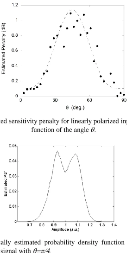
In the following figure (Fig. 6), the dependence of the penalty on the angle is clearly showed. The obtained power penalty values refer to FEC-level BER (2·10-3). As can be
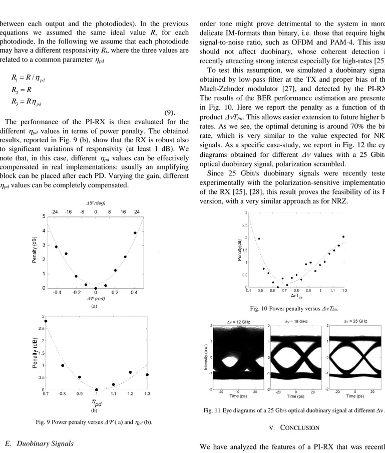
seen, the maximum variation of the sensitivity is around 1 dB. From a system point of view, it is important to analyze the statistical distribution of the signal sampled at the center of the eye diagram. In Fig. 7, we report the probability density function (pdf) of the samples for the mark level, which was numerically estimated for . This is quite similar to the well-known distribution due to the in-band crosstalk [19]. Here the apparent difference is that the spurious signal, at 2, is not an independent signal, because it has the same modulation as our signal (as shown in Eqn. 5, it is present whenever a mark is transmitted): therefore the typical distribution of beating noise is observed, without the central peak (the central peak arises when the sequences of the two signals are uncorrelated) [19].
Fig. 5 Eye diagrams taken for =1 GHz in the best and worst-case SoP condition, respectively.
Fig. 6Estimated sensitivity penalty for linearly polarized input signal as a function of the angle .
Fig. 7 Numerically estimated probability density function of the sampled mark level for a signal with
C. Impact of Local Oscillator Power and RIN
As it is well-known, the LO power (PLO) plays a key role in
determining the final sensitivity of any coherent RX. In principle, for an ideal LO the higher is its power, the better the sensitivity. However, practical sources have Relative Intensity Noise (RIN). Although low, RIN effect becomes non-negligible when PLO is very high, the condition where the best
sensitivity could be expected [21][22]. We thus run exhaustive numerical simulations to evaluate the effect of PLO value on
the RX sensitivity for the two schemes presented above. In each case we considered four RIN values, from -140 to -170 dB/Hz.
Fig. 8Sensitivity curves vs. LO power, for different RIN values in the two relevant cases: PBS on signal (left) and PBS on LO (right).
The obtained results are reported in Fig. 8, for the two RX schemes. As can be seen, at low LO power the sensitivity decreases linearly with increasing PLO. Clearly, in this region,
the scheme relaying on a PBS on the signal shows better sensitivity. This can be understood by an approximation. Let us assume perfect PI: then the sensitivity for a random SoP must be the same as for the SoP exactly aligned to one of the main axis, e.g. x-axis. Therefore, the PI-RX is in the same condition as for a common single-polarization RX, where the SoP is manually aligned. In that case, if the PBS is on the signal, all the LO power is effectively exploited. On the other hand, if the PBS is on the LO path, the RX effectively uses only 50% of the PLO (the other fraction is in the orthogonal
SoP). Thus, in this last case the sensitivity is quite worse. Notably, the simulations indicate that the RX with a PBS on the signal is performing better also when the LO power is increased so that RIN effects are relevant. It can be observed that, for each RIN value the best achievable sensitivity (the minimum of the curve) is usually slightly better when the PBS is on the signal, by around 1 dB. This again can be explained assuming perfect PI: when PBS is on the signal, the coherent gain due to LO is higher, whilst the electrical noise due to RIN is the same as in the other configuration.
Finally, we note that in the previous analysis we neglected the insertion loss of the PBS, which today can be very low, but can still slightly change these results.
D. Tolerance to the Receiver implementation issues
In the previous sections we assumed the PI-RX to be made of ideal components. In the following, we determine the system impairments due to the two main non-ideal features of the optical front-end: the deviation from ideal 120-degree mixing in the coupling and the asymmetries of responsivity/coupling loss of the 3 photodiodes. For the sake of simplicity, in the following we only consider the RX scheme with the PBS on the signal path.
First, since now we assumed the perfectly symmetrical coupler matrix M, with optimal phase shift of the signal and LO electro-magnetic fields. The elements of M depend on the total phase kl, where k is the coupling coefficient and l the length of the coupling region (for a perfect coupler, /3). Any variation of these two values affects , thus producing a coupler that has not the perfect phase differences and fixed power splitting. Indeed, real couplers can have (small) variations of both the phase and amplitude coefficients of the matrix M. We then simulated the behavior of the PI-RX, calculating the signal produced by a matrix whose is changed from /3. For these simulations we assumed a fixed
=1 GHz and a polarization-scrambled signal. Fig. 9 (a) presents the power penalty at FEC level as function of the variation of (. This indicates that the RX is quite robust, as a phase difference error of around 10% could be tolerated with a minor penalty. This conclusion is relevant: variations of
can hardly be compensated in the analog processing block, because they involve complex mathematical mixing of the signals.
Another source of impairment may be the different responsivity of the three photodiodes (in a real implementation this can also include the slight variations of the coupling
between each output and the photodiodes). In the previous equations we assumed the same ideal value R, for each photodiode. In the following we assume that each photodiode may have a different responsivity Ri, where the three values are
related to a common parameter pd
1 2 3 / pd pd R R R R R R (9). The performance of the PI-RX is then evaluated for the different pd values in terms of power penalty. The obtained
results, reported in Fig. 9 (b), show that the RX is robust also to significant variations of responsivity (at least 1 dB). We note that, in this case, different pd values can be effectively
compensated in real implementations: usually an amplifying block can be placed after each PD. Varying the gain, different
pd values can be completely compensated.
(a)
(b)
Fig. 9Power penalty versus ( a) and pd (b).
E. Duobinary Signals
The envelope-detection receiver is designed to provide a signal that, apart from the gain due to coherent detection [25], is mathematically proportional a direct-detection signal. Therefore, although the previous discussion was about NRZ signals, the RX can work with any IM signal. In the past, the polarization-dependent version was successfully tested with real optical OFDM signals [26]. This notwithstanding, in the PI implementation the residual noise due to the spurious 2nd
order tone might prove detrimental to the system in more-delicate IM-formats than binary, i.e. those that require higher signal-to-noise ratio, such as OFDM and PAM-4. This issue should not affect duobinary, whose coherent detection is recently attracting strong interest especially for high-rates [25].
To test this assumption, we simulated a duobinary signal, obtained by low-pass filter at the TX and proper bias of the Mach-Zehnder modulator [27], and detected by the PI-RX. The results of the BER performance estimation are presented in Fig. 10. Here we report the penalty as a function of the product Tbit. This allows easier extension to future higher bit
rates. As we see, the optimal detuning is around 70% the bit-rate, which is very similar to the value expected for NRZ signals. As a specific case-study, we report in Fig. 12 the eye diagrams obtained for different values with a 25 Gbit/s optical duobinary signal, polarization scrambled.
Since 25 Gbit/s duobinary signals were recently tested experimentally with the polarization-sensitive implementation of the RX [25], [28], this result proves the feasibility of its PI version, with a very similar approach as for NRZ.
Fig. 10Power penalty versus bit.
Fig. 11Eye diagrams of a 25 Gb/s optical duobinary signal at different .
V. CONCLUSION
We have analyzed the features of a PI-RX that was recently introduced and is now widely used in experimental demonstrations. We have derived the main features of the RX, indicated the optimal detuning value and determined the type of residual polarization sensitivity of the RX and the corresponding pdf of the noise.
We then estimated the tolerance values of the practical implementations, considering the deviation from ideal 120-degree mixing in the coupling and the asymmetries of
responsivity/coupling loss of the 3 photodiodes. We finally extended the concept to duobinary signals, which seems the most likely future application of our PI-RX. The presented results can be used as guidelines for future implementations and further developments.
ACKNOWLEDGEMENTS
The author gratefully acknowledges stimulating discussions with M. Presi and M. Rannello.
REFERENCES
[1] H. Rohde, S. Smolorz, E. Gottwald, and K. Kloppe, “Next generation optical access: 1 Gbit/s for everyone,” in Proc. 35th ECOC, Sep. 2009, pp. 1–3, paper 10.5.5.
[2] Y. Luo, X. Zhou, F. Effenberger, X. Yan, G. Peng, Y. Qian, and Y. Ma “Time- and Wavelength-Division Multiplexed Passive Optical Network (TWDM-PON) for Next-Generation PON Stage 2 (NG-PON2), J. Lightwave Technol. , 31, n. 4, Febr. 2015, 587-594.
[3] P. P. Iannone, A. H. Gnauck, D. T. van Veen, and V. E. Houtsma, “Increasing TDM rates for access systems beyond NG-PON2,” Journal
of Lightwave Technology 34, 1545–1550 (2016)
[4] H. Rohde, S. Smolorz, J. S. Wey, and E. Gottwald, “Coherent optical access networks,” in Proc. Optical Fiber Comm. Conference OFC/NFOEC, Mar. 2011, pp. 1–3, paper OTuB1.
[5] J. Prat, et al. “Towards ultra-dense wavelength-to-the-user: The approach of the COCONUT project” (Invited Paper), Proc. of Intern. Conf. Transp. Optical Networks, ICTON 2013, 2013, paper Tu.C3.2. [6] L. G. Kazovsky, P. Meissner, E. Patzak, “ASK multiport optical
homodyne receivers,” J. Light. Technol., 5, 6, pp. 770–791, Jun. 1987 [7] M. Presi, et al. , “All DFB based coherent UDWDM PON with 6.25
GHz spacing and a >40 dB power budget,” IEEE Photon. Technol. Lett., vol. 26, no. 2, pp. 107–110, Jan. 1, 2014.
[8] D.Lavery, et al., "Digital Coherent Receivers for Long-Reach Optical Access Networks," J. Light. Technol., vol.31, no.4, pp.609,620, 2013 [9] B. Glance, “Polarization independent coherent optical receivers”, J.
Lightw. Technol., vol. 5, no. 2, pp. 274–276, Feb. 1987.
[10] G. Marone, P. Poggiolini, and E. Vezzoni, “Polarisation independent detection by synchronous intra-bit polarization switching in optical coherent systems,” in Proc. IEEE International Conf. Communications, Including Supercomm Technical Sessions , 4, pp. 1658–1662, 1990 [11] R. Noè, “Endless polarisation control in coherent optical
communications,” Electr.. Lett., 22, 15, pp. 772–773, Jul. 1986. [12] E. Ciaramella “Polarization-Independent Receivers for low-cost
Coherent OOK systems”, IEEE Photonics Technology Letters, , vol.26, no.6, pp.548,551, March15, 2014
[13] M. Artiglia, et al. "Polarization-Independent Coherent Real-Time Analog Receiver for PON Access Systems," J. Light. Technol., 34,. 8, pp. 2027-2033, 2016.
[14] M. Rannello, et al. "10 Gb/s long-reach PON system based on directly modulated transmitters and simple polarization independent coherent receiver," Opt. Express 25, 17841-17846 (2017)
[15] A. Rafel and N. Parkin, "Cost analysis of coherent-based TRx PON network," 2015 Europ. Conf. Optical Comm. (ECOC 2015), pp. 1-3. [16] J. Tabares, S. Ghasemi, V. Polo and J. Prat, "Simplified Carrier
Recovery for Intradyne Optical PSK Receivers in udWDM-PON," J.
Light. Technol., vol. 36, no. 14, pp. 2941-2947, 15 July15, 2018.
[17] Chongjin Xie, Peter J. Winzer, Gregory Raybon, Alan H. Gnauck, Benyuan Zhu, Tommy Geisler, and Bent Edvold, "Colorless coherent receiver using 3x3 coupler hybrids and single-ended detection," Opt.
Express 20, 1164-1171 (2012)
[18] A. Davis, M. Pettitt, J. King and S. Wright, "Phase diversity techniques for coherent optical receivers," in J. Lightwave Technology, vol. 5, no. 4, pp. 561-572, April 1987
[19] E. L. Goldstein, L. Eskildsen, and A. Elrefaie, “Performance implications of component crosstalk in transparent lightwave networks,” IEEE Photon. Technol. Lett., vol. 6, pp. 657–659, 1994
[20] M. Presi, R. Corsini, M. Artiglia, and E. Ciaramella, "Ultra-dense WDM-PON 6.25 GHz spaced 8×1 Gb/s based on a simplified coherent-detection scheme," Opt. Express 23, 22706-22713 (2015)
[21] L.G. Kazovsky, et al., “Impact of laser intensity noise on ASK two-port optical homodyne receivers”, Electr. Letters. 23. 871 – 873 (1987). [22] W. H. C. de Krom, "Impact of local oscillator intensity noise and the
threshold level on the performance of a (2*2) and (3*3) phase-diversity ASK receiver," in J. Lightwave Technol., 9, 5, pp. 641-649, May 1991. [23] I. N. Cano, A. Lerín and J. Prat, "DQPSK Directly Phase Modulated
DFB for Flexible Coherent UDWDM-PONs," in IEEE Photon. Technol.
Lett., vol. 28, no. 1, pp. 35-38, 1 Jan.1, 2016.
[24] H. Kim and C. Yu, “Optical duobinary transmission system featuring improved receiver sensitivity and reduced optical bandwidth,” IEEE
Photon. Technol. Lett., 14, 1205–1207 (2002)
[25] D. van Veen and V. Houtsma, “Bi-directional 25G/50G TDM-PON with extended power budget using 25G APD and coherent amplification,” in Proc. Optical Fiber Comm. Conference and Exp., OFC 2017, Th5A.4 [26] G. Cossu, et al. "High-power budget OFDM-PON compatible with
ultra-narrow channel spacing," Proc. Europ. Conf. Optical Comm. ECOC 2014, Cannes, 2014, Paper We.1.6.4.
[27] H. Kim and C. Yu, “Optical duobinary transmission system featuring improved receiver sensitivity and reduced optical bandwidth”, IEEE
Photon. Technol. Lett.14, 1205–1207 (2002).
[28] M.Rannello, M.Presi, E. Ciaramella, “Optical vs. electrical duobinary coding for 25 Gb/s PONs based on DSP-free coherent envelope detection” Proc. Optical Fiber Comm. Conference and Exposition, OFC 2018 paper M1B.6