Scuola di Dottorato in Ingegneria “Leonardo da Vinci”
Corso di Dottorato di Ricerca in
INGEGNERIA DELL’INFORMAZIONE
Tesi di Dottorato di Ricerca
PLATFORM-BASED DESIGN, TEST AND
FAST VERIFICATION FLOW FOR
MIXED-SIGNAL SYSTEMS ON CHIP
Autore:
Tommaso Cecchini __________________
Relatori:
Prof. Luca Fanucci __________________ Prof. Roberto Saletti __________________
Anno 2011 SSD ING-INF/01
“The field is lost, everything is lost! The Black One has fallen from the sky and the towers in ruins lie The enemy is within, everywhere! And with him the Light… Soon they will be here… Go now, my lord, while there is time… There are places below” “And you know them too... I release thee! Go! My servant you'll be for all time” “As you command, my king” “I had a part in everything. Twice I destroyed the Light and twice I failed. I left ruin behind me when I returned, but I also carried ruin with me… She, the mistress of her own lust” J.R.R. Tolkien
I have many people to thank for their contribute to my work during the last three years. I maybe have to start with Giulia, all my family and my friends who believed in me. The support I had from them has been overwhelming. Then I have to thank my tutors Prof. Luca Fanucci and Prof. Roberto Saletti for their help and their guide that make my research possible.
A special thank goes to the SensorDynamics AG design centre of Navacchio because they gave me the opportunity to face with real challenges, teaching me what it means to be a good designer and showing me the right way to work hard with the maximum efficiency.
A special than goes to all my fellow PhD students for the infinite support and friendship.
Acknowledgements ... 5
Table of contents ... 7
Index of Figures... 9
Index of Tables ... 13
Introduction ... 15
Chapter 1 Sensor automotive applications ... 19
1.1
Introduction ... 19
1.2
Automotive electronic applications ... 22
i.
Chassis & safety ... 22
ii.
Powertrain... 26
iii.
Infotainment ... 29
1.3
MEMS sensors in automotive ... 31
i.
MEMS market analysis ... 31
ii.
MEMS automotive applications ... 36
1.4
MOEMS applications ... 39
i.
Display (DMD)... 40
ii.
Spectrometer... 42
iii.
IR sensors ... 44
iv.
Barcode scanner... 45
v.
Picoprojector... 46
Chapter 2 The Platform Based Design approach to a Sensor
Interface
49
2.1
Introduction ... 49
2.2
Universal Sensor Interface... 50
2.3
Platform Based Design ... 52
2.4
Limitations of Platform Based Design flow ... 54
iii.
Software section ...61
2.6
SD400 physical implementation ...62
2.7
Limitations of SD400...63
2.8
The SD4k ...64
Chapter 3 SD4k Platform...65
3.1
Description and Block Diagram...65
3.2
Overview of Analog section ...67
3.3
Overview of ARM9 section ...69
3.4
Analysis of Digital section ...71
i.
Clock Multiplexer ...75
ii.
I2C/SPI interface...78
iii.
AHB to FPGA bridge...80
Chapter 4 Multi-level test environment ...83
4.1
Introduction ...83
4.2
System Verification Flow ...86
4.3
VHDL-AMS modeling ...88
i.
Modeling Flow...89
ii.
Model Template ...89
iii.
Model Trimming ...92
4.4
Automatic Extraction of Netlist ...93
i.
Netlisting Flow...93
ii.
Connection Modules Insertion ...95
4.5
Full System Simulation and Results ...97
4.6
Environment Upgrades ...98
i.
Python script and text file ...98
ii.
Full Python environment...100
4.7
Test case: 3D consumer gyro X axis gain calibration...103
4.8
The complete environment use ...105
Conclusions...106
I
NDEX OF
F
IGURES
Figure 1-1: Automotive Electronic segments [source: Bosch]... 20
Figure 1-2: MCUs performances versus applications [source:
Freescale]... 22
Figure 1-3: Technologies enabling modern chassis. ... 23
Figure 1-4: IMUs work by detecting changes in pitch, roll, and yaw.24
Figure 1-5: Revenue and grow rate forecast for X-by-wire systems in
Europe... 26
Figure 1-6: Powertrain technologies... 27
Figure 1-7: Typical Battery Management System diagram. ... 29
Figure 1-8: Automotive entertainment system. ... 30
Figure 1-9: Global MEMS market 2005 2010... 32
Figure 1-10: Global MEMS market 2006 (source WtC) [5]. ... 34
Figure 1-11: Sensor Systems in Automotive (source WtC) [4]. ... 36
Figure 1-12: Market for Automotive MEMS sensor (source
wtc-consult). ... 37
Figure 1-13: MOEMS Market grow from 2003 to 2008. ... 40
Figure 1-14 - 1-15: Triple DMD DLP projector and single DMD
DLP projector. ... 42
Figure 1.16: An example of MOEMS spectrometer... 43
Figure 1-17: Non-invasive Bilirubin detector based on MOEMS
spectrometer... 43
Figure 1-18: Using an IR sensor it is possible to detect people
otherwise not visible at night... 45
Figure 1-19: Picoprojectors market forecasts... 46
Figure 1-20: Microvision Picoprojector. ... 47
Figure 2-1: Building a Universal Sensor Interface... 50
Figure 2-3: System platform layer and design flow. From system level
modeling to prototyping through different layers ...53
Figure 2-4: comparison between design time for a traditional Platform
Based and the ISIF flow...56
Figure 2-5: example of partitioning of a DSP chain within ISIF
platform between analog, digital and software processing blocks...57
Figure 2-6: ISIF block diagram...58
Figure 2-7: ISIF input channel. ...59
Figure 2-8: ISIF digital section. ...60
Figure 2-9: SD400 Physical implementation. ...62
Figure 2-10: SD400 Layout. ...63
Figure 3-1: SD4k Simplified Block Diagram ...66
Figure 3-2: Input channel ...68
Figure 3-3: Simplified Block Diagram of the analog section ...69
Figure 3-4: Simplified Block Diagram of the ARM core ...71
Figure 3-5: High Speed structures of the digital section of the SD4k 72
Figure 3-6: Low Speed structures of the digital section of the SD4k .74
Figure 3-7: Clock Multiplexer block diagram ...76
Figure 3-8: Timing Diagram ...77
Figure 3-9: Clock gating structure ...78
Figure 3-10: Clock Gating Timing constraints ...78
Figure 3-11: I2C/SPI IP Simplified Block Diagram ...80
Figure 3-12: AHB to FPGA bridge Simplified Block Diagram ...81
Figure 4-1: Mixed Signal on overall SoC(%). Source Industry analyst
IBS Corporation ...84
Figure 4-2: Most Common Causes of Silicon Failure ...85
Figure 4-3: System Verification Flow ...87
Figure 4-4: Generic Analog Block and its Simplified VHDL-AMS
Model ...88
Figure 4-5: Template sections...90
Figure 4-6: Template description ...90
Figure 4-7: Terminal check...92
Figure 4-8: Self-checking Test Bench ...93
Figure 4-9: Netlist Extraction Flow ...94
Figure 4-10: Connection Modules Insertion Rules ...95
Figure 4-11: Logical to Electrical Connection Module ...96
Figure 4-12: Electrical to Logical Connection Module ...96
Figure 4-13: Introducing Python scripts into test environment ...97
Figure 4-14: Example of parameter split into two not adjacent
registers ...99
Figure 4-15: Advanced Python co-simulation environment... 100
Figure 4-16: Simulation console snapshot ... 104
I
NDEX OF
T
ABLES
Table 1-1: Global Markets and Forecasts for MEMS Systems,
Devices, Materials and Equipment (Yole Development). ... 33
Table 1-2: Mechanical properties of steel versus silicon [2]... 35
I
NTRODUCTION
In the last few years, automotive field has become one of the most dynamic but even complicated manufacturing sectors in the world. It pointed out how the increase of sophisticated and leading-edge emerging electronic technologies can be rapid. Car companies consider electronic development as the key point to meet very heterogenic requirements such as high-safety, comfort, infotainment, gas emission reduction, power saving, low cost and short time to market. For these reasons the expectations on the electronic automotive systems are very high and nowadays this sector seems to be one of the most innovative, challenging and competitive of all the market fields. If we take a look to some numbers, we can easily have an idea of the current situation: the 80% of technology innovation in cars is made of new electronics, the 20% of a vehicle’s cost is related to electronics devices, the 15% of micro processor systems are absorbed by automotive and, in a car, there are more than 100 sensors and micro processors systems. We have to consider that all these numbers are still growing fast.
Following this trend, latest refinements in photolithography techniques has featured an increasing shrinking of dimension of sensing elements up to the development of Micro Electro Mechanical Systems (MEMS) and Micro Opto Electro Mechanical Systems (MOEMS) in which mechanical and optical elements, sensors, actuators and electronics are integrated on a common silicon substrate. If in the last decades the diffusion of measurement systems was limited by high costs, large size and low reliability, the new generations of MEMS sensors guarantee remarkable savings in cost, area and power consumption, featuring a fast and deep market penetration.
The scenario has evolved to a complex mixed-signal chip to be designed in a very short time, due to the low time-to-market, guaranteeing a high level of reliability and a strong fail-safe policy.
Of course, costs must be reduced to the minimum, avoiding re-design phases and further silicon runs.
Taking into account all the aspects mentioned above, this research is then providing methodologies to enhance the design phase from architectural space exploration and system study to verification of the whole mixed-signal system. At the beginning of the work, some innovative digital IPs have been designed to develop efficient signal conditioning for sensor systems on-chip that has been included in commercial products. After this phase, the main focus has been addressed to the creation of a re-usable and versatile test of the device after the tape-out which is close to become one of the major cost factor for ICs companies, strongly linking it to model’s test-benches to avoid re-design phases and multi-environment scenarios, producing a very effective approach to a single, fast and reliable multi-level verification environment. All these works generated different publications in scientific literature. The compound scenario concerning the development of sensor systems is presented in Chapter 1, together with an overview of the related market with a particular focus on the latest MEMS and MOEMS technology devices, and their applications in various segments.
Chapter 2 introduces the state of the art for sensor interfaces: the generic sensor interface concept (based on sharing the same electronics among similar applications achieving cost saving at the expense of area and performance loss) versus the Platform Based Design methodology, which overcomes the drawbacks of the classic solution by keeping the generality at the highest design layers and customizing the platform for a target sensor achieving optimized performances. An evolution of Platform Based Design achieved by implementation into silicon of the ISIF (Intelligent Sensor InterFace) platform is therefore presented. ISIF is a highly configurable mixed-signal chip which allows designers to perform an effective design space exploration and to evaluate directly on silicon the system performances avoiding the critical and time consuming analysis required by standard platform based approach. In chapter 3 we describe the design of a smart sensor interface for conditioning next generation MOEMS. The adoption of a new, high performance and high integrated technology allow us to integrate not only a versatile platform but also a powerful ARM processor and various IPs providing the possibility to use the platform not only as a conditioning platform but also as a processing unit for the application. In this chapter a description of the various blocks is given, with a particular emphasis on the IP developed in order to grant the highest grade of flexibility with the minimum area occupation.
The architectural space evaluation and the application prototyping with ISIF has enabled an effective, rapid and low risk development of a new high performance platform achieving a flexible sensor system for MEMS and MOEMS monitoring and conditioning. The platform has been design to cover very challenging test-benches, like a laser-based projector device. In this way the platform will not only be able to effectively handle the sensor but also all the system that can be built around it, reducing the needed for further electronics and resulting in an efficient test bench for the algorithm developed to drive the system.
The high costs in ASIC development are mainly related to re-design phases because of missing complete top-level tests. Analog and digital parts design flows are separately verified. Starting from these considerations, in the last chapter a complete test environment for complex mixed-signal chips is presented. A semi-automatic VHDL-AMS flow to provide totally matching top-level is described and then, an evolution for fast self-checking test development for both model and real chip verification is proposed. By the introduction of a Python interface, the designer can easily perform interactive tests to cover all the features verification (e.g. calibration and trimming) into the design phase and check them all with the same environment on the real chip after the tape-out. This strategy has been tested on a consumer 3D-gyro for consumer application, in collaboration with SensorDynamics AG.
Chapter 1
S
ENSOR
AUTOMOTIVE
APPLICATIONS
1.1
Introduction
Today, electronics in automotive fields, like car sector, is knowing a incredible fast growing period. Automotive innovation and development is strictly correlated to electronic. Recent statistics show that about the 90% of innovation in new cars are electronic based, with global industry analysts forecasting that by 2010 electronic content will account for 40% of cost of a typical mid-sized. Moreover the world market for non-entertainment automotive electronics was estimated at US$36.8 billion in 2005 and is forecast to reach US$52.1 billion by 2010 that represents an increase of about the 40% in only five years. This incredible and fast growing will be possible thanks to the introduction of new products in quite all of the four main areas of the automotive electronic reported for simplicity in figure 1-1. While powertrain sector, accounted up to now to cover about the 32% of global market, will remain stable, safety, driving assistance modules and infotainment will show a dramatic increase. The request of new products in these fields is coming from two main different subjects. First of all governments are introducing continuously new laws to improve safety and reduce CO2 emissions. Reinhard
Schulte-Braucks, head of the automotive unit of the Enterprise and Industry Directorate-General of the European Commission, says car makers will have to reduce CO2 emissions to reach the
community target of 120g/km by 2012 and enhance road safety through crash-avoidance technologies.
Figure 1-1: Automotive Electronic segments [source: Bosch] The requirements are detailed in the CARS 21 (Competitive Automotive Regulatory System for the 21st Century) strategy being promoted by the European Commission.
Another key factor for automotive companies is represented by the requirements coming from mature markets, such as the European and USA ones. Customers are looking for more and more comfort and security as well as an increasing number of entertainment systems. Such requests range from the basic control of climate, lighting, and humidity to the automatic setting of seat, rear view mirrors, steering wheel position according to the driver’s physique, improved navigation assistance and infotainment products.
This scenario is representing a big challenge for semiconductors companies and automotive manufacturers. During these years
these companies have been going through a period of significant change and consolidation, a trend which is expected to continue and across all tiers of the industry. Recent examples include Continental’s acquisition of Motorola’s automotive electronics business and the acquisition of Siemens VDO automotive AG; Valeo’s acquisition of Johnson Control’s engine controls business; and Siemens VDO’s acquisition of DaimlerChrysler’s Huntsville Electronics. Contemporaneously systems and components suppliers are looking to reduce costs by moving production in the South-East Asia to lower cost locations. These changes and consolidations are done in order to improve productivity and give a proper answer to actual and future automotive market challenges. From a more technical point of view, automotive manufacturers are under continuous pressure to fulfil market and governments requirements and they all agree that electronic is the key to solve in time the tensions between these different requirements and meet low cost production.
Anyway, these requirements are pushing towards an increase of complexity of electronics into cars. In today’s luxury cars, up to 2500 signals (i.e., elementary information such as the speed of the vehicle) are exchanged by up to 70 Electronic Control Units and this trend continues to grow very fast. Many safety applications such as Anti-lock Braking System (ABS), vehicle stability control and occupant protection, so far independent, will have to communicate with each other for optimal safety. In addition, new driver assistance systems such as autonomous cruise control, lane departure warning, night-vision and blind-spot monitoring will be introduced, requiring semiconductor-based sensors and high-performance processors and memory resources. Moreover automotive experts agree on the fact that in the next few years “X-by-Wire” will play a key role on the growing of electronics in car and will completely change some important fields of the automotive industry.
In this scenario the performances of microcontroller units (MCUs) play a key role on the achievement of the aforementioned goals. They first entered the automobile for purposes of engine control in 1970s and since then, MCU computing performances have multiplied by 20. A recent agreement between Freescale and Continental has been signed to develop the first triple-core 32-bit microcontroller for next generation electronic braking systems (EBS). The multi-core approach is promising to increase performances, reduce power consumption and combine different functions in a single ECU (figure 1-2).
Figure 1-2: MCUs performances versus applications [source: Freescale]
1.2
Automotive electronic applications
In this paragraph we will see in much more details some of the most important automotive electronic applications. In particular we will focus on actual system solutions and on future trends. The target is to understand what the electronic world is expected to do in the automotive field and consequently which are the most industrial relevant research activities in this area.
i.
Chassis & safety
Safety is certainly a driving factor for automotive since governments laws and customers are strongly requiring a continuous evolution. In this scenario modern chassis systems play an increasingly important part in autonomous safety and also in efficient vehicle operation. In figure 1-3 are reported some of the main actual technologies enabling modern and efficient chassis. Anti-Lock Braking Systems (ABS) are designed to maintain driver control and stability of the car during emergency braking. Locked wheels will slow a car down but will not provide steering ability. ABS allows maximum braking to be applied while retaining the ability to “steer out of trouble”. The operation of ABS can slightly reduce stopping distance in some cases like on wet road surfaces, but it can increase the stopping distance in others, as may be the case in deep snow or gravel.
Figure 1-3: Technologies enabling modern chassis.
An ABS system monitors four wheel speed sensors to evaluate wheel slippage. Slip can be determined by calculating the ratio of wheel speed to vehicle speed, which is continuously calculated from the four individual wheel speeds. During a braking event, the function of the control system is to maintain maximum possible wheel grip on the road - without the wheel locking - by adjusting the hydraulic fluid pressure to each brake by way of electronically controlled solenoid valves. For passenger car applications, the majority of ABS components are often housed together in a single, under-hood mounted module. ABS systems make use of modern Micro Electro-Mechanical Sensors (MEMS) and in particular of gyroscopes and accelerometers.
MEMS are widely used in safety applications since they allow very sensitive and reliable solutions while lowering dramatically area occupation and overall costs. For example they are used to build electronic stability program (ESP) systems. They consist in the detection of a difference between the driver's control inputs and the actual response of the vehicle. When differences are detected, the system intervenes by providing braking forces to the appropriate wheels to correct the path of the vehicle. This automatic reaction is engineered for improved vehicle stability, particularly during severe cornering and on low-friction road surfaces, by helping to reduce over-steering and under-steering. Since ESP is an evolution of ABS, additional sensors must be added to the “old” ABS system. A steering wheel angle sensor is used to detect driver input with a yaw rate sensor and a low-g accelerometer sensor that measure the vehicle response. Some ESP systems include a connection to the powertrain controller of the vehicle to enable reductions in engine torque when required.
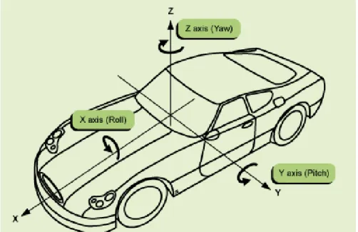
In the near future ESP, ABS, Traction Control System (TCS), powertrain and navigation modules will have to communicate each other to really improve the level of safety. This will require a higher computational power as previously underlined (see figure 1-2) and also improved MEMS and electronic solutions. In fact one of the main targets for the future is the realization of compact, reliable and cost efficient Inertial Measurement Units (IMUs). An IMU works by detecting the current rate of acceleration and changes in rotational attributes in the X, Y and Z-axis (see figure 1-4
Figure 1-4
).Figure 1-4: IMUs work by detecting changes in pitch, roll, and yaw.
It consists of three accelerometers and three gyroscopes used in combination to provide a complete control on vehicle movements. Many companies such as Continental, Freescale and SensorDynamics AG are investing so much in the IMU development since it would bring many safety modules - such as the aforementioned ABS, ESP and TCS - and navigation modules in a single one, thus leading to an evident advantage in terms of cost, area occupation and performances.
MEMS find another important application in airbag systems. Basic systems that serve as frontal collision protection for front seat occupants are being replaced by intelligent, high-end airbag systems that also include side protection for both the front and
and knee protection. For example while the detection of the passengers and their motion can be performed by a seats-based MEMS X-Y accelerometer, the airbag system can be positioned differently in a car, allowing multiple information determination such as identification of type of collision, its direction and the g-force impact; in this way a specific and dedicated airbag reaction can be guaranteed. As a consequence airbag algorithms are becoming significantly more complex requiring greater computational performances. In addition modern solutions implement one more inertial sensor signal linked to a watchdog MCU used to double-check that the “crash” has really happened. Another important application in chassis & safety is the Electric power assisted steering (EPS). EPS uses an electric motor to provide directional control to the driver. Most EPS systems have variable assist, which provides more assistance as the speed of a vehicle decreases and less assistance from the system during high-speed situations. This functionality requires a delicate balance of power and control that has only been available in recent years. In the event of component failure, a mechanical linkage such as a rack and pinion serves as a back-up in a manner similar to that of hydraulic systems. In the next future many experts agree on the fact that EPS will completely replace electro-hydraulic power steering systems (EHPS). In fact the benefits of EPS compared to EHPS are numerous: it enhances safety, increases fuel economy, provides varying levels of “road feel”, and allows car designers more flexibility. The main challenge is the power management because in the biggest vehicles the current required to actuate electric motors is very high.
Electrohydraulic braking (EHB) systems are designed to allow electronic control of vehicle braking while retaining a reduced hydraulic system. The hydraulic system functions as a reserve in the event of a failure in the electronic control. The EHB control unit receives inputs from sensors connected to the brake pedal. In normal operation, a backup valve is closed and the controller activates the brakes of the wheels through an electric motor driven hydraulic pump. When the controller goes into a fail-safe mode, the backup valve is opened, which allows the brakes to be controlled through a conventional hydraulic circuit. The trend on braking system is to completely remove hydraulic systems moving to new solutions called Electromechanical Braking (EMB) or Brake-By-Wire. EMBs replace conventional hydraulic braking systems with a completely “dry” electrical component system. This occurs by replacing conventional actuators with electric motor driven units. This move to electronic control eliminates many of the manufacturing, maintenance, and environmental concerns
associated with hydraulic systems. Furthermore an all electric solution enables simpler integration of such higher-level functions as TCS and Adaptive Cruise Control (ACC). One of the main challenges for this new system is again power management as mentioned for EPS. Quite all experts think that a switch to 42V power supply will be needed to deliver more power. Moreover an electric system needs a high level of safety and this means that EMB components merit higher level of analysis, design and verification, they must be networked using high-reliability bus protocols that ensure comprehensive fault tolerance and chip redundancy must be granted.
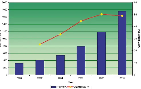
EMB is not yet in industrialization but quite all automotive companies are investing on that. The expectations on these new systems are enormous (figure 1-5) especially in the sector of small vehicles. By 2010 the market is expected to have a volume of EUR 1.1 billion, while for 2015 EMB could reach a market penetration of 20/25 %. In fact many producers such as Fiat, Renault and Volkswagen are likely to fit their small and middle range cars with EMB to enhance profitability.
Figure 1-5: Revenue and grow rate forecast for X-by-wire systems in Europe.
ii.
Powertrain
Powertrain represents for sure the core of automotive. Electronic has appeared in this field since the 1970s when the stringent automobile emission regulations introduced in the United States
immediately showed that a completely mechanical automobile couldn’t give an efficient solution. Now electronic powertrain has the crucial role to reduce fuel emission meeting new requirements of CO2 emissions while maintaining or increasing engine power as
requested by customers. In figure 1-6 are sketched some of the main electronic features of powertrain. Probably the most known electronic powertrain application is the engine control. It first came out in 1978 and since then it has changed dramatically.
Figure 1-6: Powertrain technologies.
Modern electronic control systems are designed to meet legislative mandated exhaust emission levels, to provide competitive fuel economy, to meet customer quality expectations and to enhance the “fun to drive” factor. All system are based on a powerful microcontroller that is in continuous communication with many different devices that can interface with the harsh world of the engine and its complement of electro-mechanical sensors, solenoids, relays, injectors, coils, motors, actuators and other power managing devices. These systems always implement a high level of safety recurring to additional safety microcontrollers that continuously monitor the status of the engine, implementing failure and diagnostic routines. Consequently engine MCUs have to deal with a lot of input and output analog and digital signals to be processed in real time and coming from different parts of the car: cam position controller, wheel speed detector, temperature sensors, battery management unit, mass air flow system, throttle position system, oxygen sensors, relays, cam, throttle and fan control, injector system and so on. The system must survive in the harsh engine compartment environment thus satisfying strict
specifications such as reverse battery, load dump, inductive load spikes, over current, over voltage and high temperatures.
Now it’s clearer that around the engine control ECU there are a lot of devices, each one related to a particular application. For this reason now we focus only on some of the most relevant from a research point of view.
The need to improve engine performance, reliability while reaching environmental targets is leading to the wide utilization of sensors. Nowadays all cars utilize mass air flow sensors to determine the mass of air entering a fuel-injected engine. The data from the sensors are used by the engine ECU to calculate and deliver the correct fuel mass to the engine. These kind of sensors can be implemented recurring to different solutions like hot wire sensors or “coldwire” sensors.
Crankshaft and camshaft sensors are used to control the mechanical movements of the engine. In modern automotive systems the data from these two sensors are used together to monitor the relationship between pistons and valves and to increase the efficiency of the engine. Moreover they are used for the measurement of the engine speed in revolutions per minute. These sensors typically consist of magnets and an inductive coil or they can be based on the Hall Effect.
Pressure and temperature sensors based on many different technology solutions are extensively implemented to monitor the correct functionality of the engine.
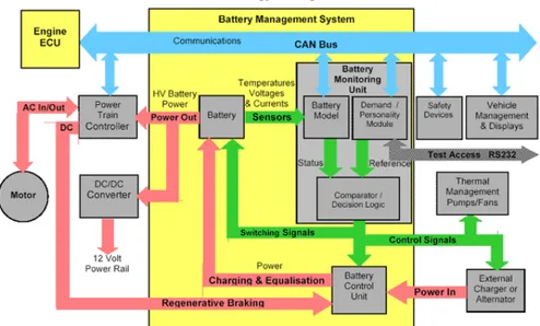
Battery Management Systems (BMSs) are gaining relevance since car power budget continues to increase thus pushing 14V automotive standard to crisis. Automotive BMS is highly complicated because it has to interface with a number of other on board systems and it has to work in real time in rapidly changing charging and discharging conditions as the vehicle accelerates and brakes (figure 1-7). It typically consists of a Battery Management Unit (BMU) and a Battery Control Unit (BCU). BMU is based on a microprocessor that has to manage many functions: one of the most important is the battery model function that consists in the continous monitoring and logging of the State Of Charge (SOC) of the battery. This is very important to coordinate the activity of the battery, calculating the maximum charging and discharging energy. The BCU contains all the BMS power electronic circuitry and it takes the inputs from the BMU to control battery charging and to switch the power connections to individual cells. Moreover it implements faulty routines to isolate the battery in case of alarm or fault conditions. Electric motors are used to implement many functions in a car (e.g. engine cooling fan, water pump) and in the
near future they are expected to be much more employed to replace mechanical or hydraulic actuated systems.
We already spoke about brake-by-wire and electric power assisted steering, but the X-by-wire technology finds other important applications. One of the most important in the powertrain sector is the electronic valve control (EVC) that is replacing the mechanical camshaft with single actuators for each valve for time independent driving. These actuators are typically electric motors controlled by the engine ECU.
Figure 1-7: Typical Battery Management System diagram. The advantages of this solution are numerous: increase of the engine power and fuel economy; features like adaptive cruise control, TCS and ESP become easier to be implemented. On the contrary valve control becomes much more power consuming if compared with mechanical solutions.
iii.
Infotainment
Consumer demand for innovation continues to drive the rapid evolution of infotainment into cars. People wants to view movies, watch television, play video games, experience high-quality audio and have intelligent and fast navigation systems. Obviously automotive infotainment gets a lot of innovation from other industrial domains that are growing and progressing in the technology race at a very fast rate. Moreover while power saving is in common with the other automotive fields, the environment
characteristics such as the temperature are less restrictive thus leading to a fast technology growing. In figure 1-8 is sketched a diagram of entertainment and information system into a modern vehicle.
Figure 1-8: Automotive entertainment system.
There are many examples of infotainment applications: cellular communication, audio and video systems, intelligent navigation systems based on Global Positioning System (GPS), vehicle diagnostics and so on. The use of hard drives or flash drives in vehicles that could hold entire music libraries, games and movies for back-seat passengers is coming out on the market. Control of a device with voice commands will be possible in the near future using hybrid architecture that combines a MCU with a digital signal processor (DSP). A recent market research [1] shows that one of the major trends in the market is the realization of multi-featured systems that are expected to increase from 76M units in 2005 to 97M units in 2012 representing a CAGR of 3% per year. In the next few years this market will be most significantly impacted by new digital audio products that play ‘soft’ music files, digital broadcast technologies, connectivity to digital music players and stored files and emerging display based entertainment systems.
1.3
MEMS sensors in automotive
i.
MEMS market analysis
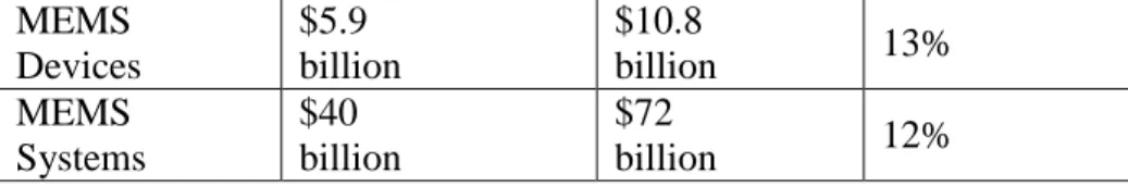
In the last few years the density of electronic devices has exponentially grown thanks to the recent technological advances. Moreover the new progresses of micro-mechanical technology have featured the miniaturisation of sensing elements achieving complete sensor systems on a common substrate of silicon with the conditioning electronics. The new potentialities of MEMS devices have opened the way for a broad diffusion of sensing and actuating systems in a wide range of application fields. In fact, if in the last decades the diffusion of sensors and complete measurement systems was limited by the costs, the size and the low reliability, the new generations of MEMS sensors achieve high reduction of costs, area and power consumption. These systems have proven to be a key enabling technology of developments in areas such as transportation, telecommunications and health care, but the range of MEMS applications covers nearly every sector. According to latest updated technical market research report (a comprehensive new market research from SEMI and Yole [2] July 18, 2007), the global market for MEMS devices and production equipment reached $40 billion in 2006, and is expected to rise to $56 billion by 2009 and $72 billion by 2011, for a compound annual growth rate (CAGR) of about 12% over the five-year.
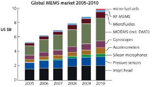
The MEMS devices at the heart of these systems overall amounted to $5.9 billion in 2006, and are forecast to grow to $10.8 billion in 2011, with a compound annual growth rate (CAGR) of 13 percent (refer to figure 1-9), pushed by the emerging employment in consumer electronics. MEMS devices are defined as die-level components of first-level packaging and comprise: pressure sensors, micro-resonators devices, accelerometers, gyroscopes, micro-RF devices, microphones, digital mirror displays, anemometers, etc.
Figure 1-9: Global MEMS market 2005 2010
MEMS materials market can be partitioned into substrates and chemicals and other materials: together these markets consisted in $433 million in 2006 and are forecast to reach $806 in 2011. All materials are expected to be subject for five-year to a CAGR of 13% up to 2011 pushed by a demand driven by substrates, (representing more than 70% of the market), packaging coatings and emerging employment of chemical mechanical planarization (CMP). The MEMS equipment worldwide market amounted to $646 million in 2006, and is forecasted to achieve $838 million in 2009 and $999 million in 2011 with a five-year CAGR forecast for of 9%. Demand for MEMS equipment and materials also is poised for solid growth thanks to the increasing employment of etching technologies (notably deep reactive ion etch) by MEMS manufacturers, as well as for wafer-level bonding equipment in MEMS system packaging (see table 1-1).
Markets
2006
2011
Compound
Annual
Growth Rate
MEMS
Materials
$433
million
$806
million
13%
MEMS
Equipment
$646
million
$999
million
9%
MEMS
Devices
$5.9
billion
$10.8
billion
13%
MEMS
Systems
$40
billion
$72
billion
12%
Table 1-1: Global Markets and Forecasts for MEMS Systems, Devices, Materials and Equipment (Yole Development). The world MEMS sensors market is fuelled by the increasing demand from different application fields, such as automotive and consumer electronics. The outstanding success of electronic stability control (ESC) and electronic safety active assistance systems joined with regulations passed by the worldwide safety authority that impose a growing adoption of security control in automobiles, are pushing the growth of the automotive segment. Furthermore the automotive technology has opened the way for the adoption of inertial sensors for adding functionality and safety in devices such as mobile phones, gaming devices and notebooks, determining a vertical growth in the consumer segment.
MEMS-based systems are also estimated to have a considerable potential in market segments such as life sciences, defence and environmental monitoring and protection, leading to continued commitment by government authorities and governmental agencies for this technology. The US and the European Union are promoting increasing investments in the employment of MEMS technology for a wide range of applications.
Furthermore funding from venture capitalists (VCs) is also expected to play a key role in the growth of the world MEMS sensors market.
Although the MEMS market is currently fragmented, both in terms of the types of devices being produced and the companies producing them (see figure 1-10). The latest projection [3] states that in the upcoming future over the next ten years, MEMS components trend will follow an increasing integration into single modules that will replace existing electronics systems. Moreover MEMS manufacturing will be absorbed by mainstream semiconductor companies. Nowadays it is a matter of fact that MEMS technology is replacing a growing number of non-silicon devices and the global sensor market is migrating from the component sensors to integrated devices. For example, several leading companies, (including Bosch, BEI Technologies, Invensense, and Honeywell) are focusing on MEMS-based inertial measurement systems to substitute non-silicon accelerometers and gyroscopes not only for automotive applications but also for a
wide range of other fields, and even companies such as Knowles and Akustica are merging silicon microphones into acoustic devices. Furthermore, companies oriented to consumer applications are pushing the demand for integrating MEMS devices into modules aimed at replacing optical auto-focus and zoom functions in mobile phones [4].
Figure 1-10: Global MEMS market 2006 (source WtC) [5]. As a result of this trend a high level of interest has arisen around MEMS technology from twofold directions: business one and technical one. On business side MEMS systems are proved to be increasingly attractive because multiple emerging markets for MEMS devices promise large financial gain and this potential for growth is confirmed by a growing amount of venture capital industry investment into MEMS based companies. On the other hand technical attractiveness is determined by multiple factors: the cost of the single sensor device is directly related to its size and, as it does for ICs, it scales down with the upcoming technologies.
The MEMS devices display excellent mechanical properties, which are guaranteed by an extremely pure crystalline structure. Silicon features a perfect fitting material for sensors devices thanks to the removal of mechanical fatigue and hysteresis phenomena. In single crystal form, silicon is an almost perfect Hookean [2] material, thus when it is flexed there is virtually no hysteresis and hence no consequent energy dissipation. Moreover silicon perfectly fits applications in which repeatable motions are required since it
suffers very little fatigue, featuring lifetimes in the range of billions to trillions of cycles without breaking. Its mechanical properties are comparable to steel (see table 1-2).
Steel
Silicon
Units
Yield
strength
< 4.2
7.0
1010
dyne/cm2
Young`s
Modulus
2.1
1.9
1012
dyne/cm2
Density
7.9
2.3
Gram/cm3
Thermal
conductivity
0.97
1.57
W/cm°C
Mechanical
hysteresis
Yes
No
Sensitivity to
stress
Low
High
Fabrication
resolution
10
0.01
µm
Fatigue
failures
Yes
No
Table 1-2: Mechanical properties of steel versus silicon [2]. We can resume the main advantages as follows:
• Technology infrastructures for developing MEMS are already available and quite well established, comprising: batch-wafer processing, cutting-edge IC processing equipment, complicated diagnostic equipment, design and simulation tools and high-volume IC packaging technologies, even though new technology progresses always require a continuous research for new development and design strategies for facing the growing market demand.
• System on a chip can be created embedding conditioning electronic on the same silicon substrate (system on a chip) or at least on the same package (system on package) for
developing low-cost integrated mechanical, optical, and biological systems.
• The pool of educated silicon processing technologists is available even though the market demand requires always new forces.
•
MEMS can be used as a packaging vehicle for nano devices, suggesting synergy with nanotechnology.Furthermore there is now a widely shared vision among chip designers, suppliers, as well as original equipment manufacturers (OEMs): a clear commitment for improving the use of the technology in a wide range of market segments. In addition the growing popularity of novel features related to sensing introduction in the final user’s applications is expected to spur the use of sensor system in particular fields such as consumer and automotive (e.g. the increasing demand for advanced safety systems as well as driver infotainment systems on chips in automobiles, see figure 1-11).
Figure 1-11: Sensor Systems in Automotive (source WtC) [4].
ii.
MEMS automotive applications
Since MEMS devices got their start in the automotive industry in the 1960s, the motor vehicle industry has gradually introduced electronic technology to perform many of the control functions previously performed mechanically or by hydraulic actuators and today's high-end vehicles feature up to 100 different sensors
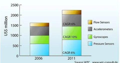
among which about 30 these are now MEMS, and the percentage is forecasted to grow. The market is composed by accelerometers, gyroscopes, pressure and flow sensors. Latest applications comprise IR sensors for air quality, micro-mirrors for displays. According to [2] the automotive segment is accounted for $1.6 billion, making this the second biggest opportunity after IT peripherals and inkjet print heads. By 2011 the market will top $2.2 billion, with a CAGR of roughly 7% (see figure 1-12).
Figure 1-12: Market for Automotive MEMS sensor (source wtc-consult).
Hereafter we depict some of the main sensing applications in the automotive sector:
• Active safety represents the most important requirement in modern vehicles. The MEMS accelerometers and gyroscopes are both sensors which can perfectly fit active safety requirements in the automotive domain [5]. The well known ABS (Anti-lock Braking System) prevents the wheels from locking while braking, Cornering Brake Control (CBC) performs stabilisation during partial braking while cornering. Traction control system (TCS) is designed to prevent loss of traction. Furthermore sensor systems are employed in the correction of drive trajectory: Electronic (Dynamic) Stability Control (ESC, ESP) compares the driver's intended direction to the vehicle's response via lateral acceleration, rotation (yaw) and individual wheel speeds. ESC then brakes individual front or rear wheels and/or reduces engine power as needed to get correct under steer or over steer. Some systems feature anti-collision detection like Adaptive
(Active, Intelligent) Cruise Control (ACC, ICC) which uses either a radar or laser setup to slow the vehicle when approaching another vehicle and Lane Departure Warning system (LDW) which warns the driver when the vehicle begins to move out of its lane.
• Intelligent Light Positioning is gaining relevance in high end cars and is expanding down to more market segments. MEMS sensors like accelerometer and gyroscope can lead to a new generation of head lights enhancing road illumination and guaranteeing safer driving conditions. Thanks to motion detection and assisted by GPS systems, the alignment of head light to various road conditions (e.g. asphalt, curves, uphill, downhill) and depending on vehicle condition (e.g. speed type pressure, suspensions, number of occupants) can be automatically performed.
• Intelligent Airbags care to soften impact for passengers during car crashes can also be efficiently performed. Since the airbag system must act at the right instance and also with the proper force toward the car occupants, the identification of type of collision, its direction and the g-force impact assume critical importance. The adoption of MEMS accelerometer, thanks to their high integration capability and accuracy, can lead to detection system of new generation replacing standard electromechanical system, achieving enhanced passenger care. Since the instant of the impact cannot be predicted in advance, it is extremely important to detect for each passenger the seat position and if in the crash the occupant is lifted from the seat. The MEMS accelerometer can determine the correct positioning of car occupants to dose the force of airbags bang.
• Vehicle Monitoring is devoted to check up the car condition to anticipate the detection of any malfunctioning. The tire correct condition can be determined through tire pressure sensors, and MEMS sensors, thanks to the compact size and high accuracy, embody optimal candidates. Furthermore the monitoring of machine vibrations can avoid excessive power consumption and accelerated wearing on bearings, seals and foundations. Vibrations can be detected by accelerometer systems for measuring vibrations frequency, amplitude (strength) and spectrum (signature) to identify the particular vibration.
• Satellite navigation systems in vehicles can determine the position of the car anywhere on the world by radio signals from Global Positioning System (GPS) satellites. Nevertheless, data from satellite is not sufficient to constantly determine the correct positioning since the satellite signal could not be always available due to shadowing by buildings and overpasses, especially in crowded urban areas. In this scenario, a dead reckoning GPS system can replace the navigation system continuing tracking movements during the time when satellite signals are not available. MEMS-based gyroscope and a magnetometer can path the motion direction and together with an accelerometer can implement complementary tracking system to GPS.
•
Enhanced Antitheft System can take advantage of accelerometers and inclinometers to sense the inclination of the car or motorbike versus the ground. As a drag truck is used to steal a vehicle, when the car is lifted the accelerometer can notice the change in inclination, activating the alarm and all the related security systems.1.4
MOEMS applications
Micro-Opto-ElectroMechanical systems represent a subset of the MEMS family that has been developed since the ’90s for fiber optics telecommunication applications [3]. However, the sudden crisis in 2001 has changed the landscape, as most of the companies developing or manufacturing optical MEMS for telecom have shut down. Historically, optical MEMS have been successfully used for TV and projection systems (this is the case of TI DLPs technology). Following the telecom downturn, some companies have succeeded to explore several new applications that are widespreading the use of optical MEMS. Despite the difficulties that global market has encountered in the last part of the 2008, MOEMS market has increased from 2003 to 2008 with an outstanding Compound Annual Grow Rate (CAGR) of more than 30% passing from 780 million dollar in 2003 to more than 3 billion dollar in 2008 as shown in figure 1-13.
Figure 1-13: MOEMS Market grow from 2003 to 2008.
Actually the most important fields were MOEMS are employed include: • Displays (DMD) • Spectrometry • IR imaging • Barcode Readers • Picoprojectors
i.
Display (DMD)
Digital Micromirror Device (DMD) is a spatial light modulator developed at Texas Instruments that is the core of Digital Light Projection (DLP) technology, and was invented in 1987.
A DMD chip has on its surface several hundred thousand microscopic mirrors arranged in a rectangular array which correspond to the pixels in the image to be displayed [6]. The mirrors can be individually rotated ±10-12°, to an on or off state. In the on state, light from the projector bulb is reflected into the lens making the pixel appear bright on the screen. In the off state, the light is directed elsewhere (usually onto a heatsink), making the pixel appear dark.
To produce greyscales, the mirror is toggled on and off very quickly, and the ratio of on time to off time determines the shade produced (binary pulse-width modulation). Contemporary DMD chips can produce up to 1024 shades of gray.
2003 600 120 381 Display (DMD) IR imager Spectrometry Barcode Reader 2008 595 96 230 0 2,8
The two main application of DLP systems are front projectors (small standalone projection units) and DLP rear projection television.
Projectors can be equipped with a single DMD chip or with three chips. The first solution employs a spinning colour wheel between the light source and the DMD. The colour wheel is usually divided into four sectors: the primary colours (red, green and blue) and an additional clear section to boost brightness. Since the clear sector reduces colour saturation, in some models it may be effectively disabled and in others it is omitted altogether. Some projectors may use additional colours (for example, yellow).
The DMD chip is synchronized with the rotating motion of the colour wheel so that the green component is displayed on the DMD when the green section of the colour wheel is in front of the lamp. The same is true for the red and blue sections. The red, green, and blue images are thus displayed sequentially at a sufficiently high rate that the observer sees a composite "full colour" image. In early models, this was one rotation per frame. Later models spin the wheel at two or three times the frame rate, and some also repeat the colour pattern twice around the wheel, meaning the sequence may be repeated up to six times per frame [3].
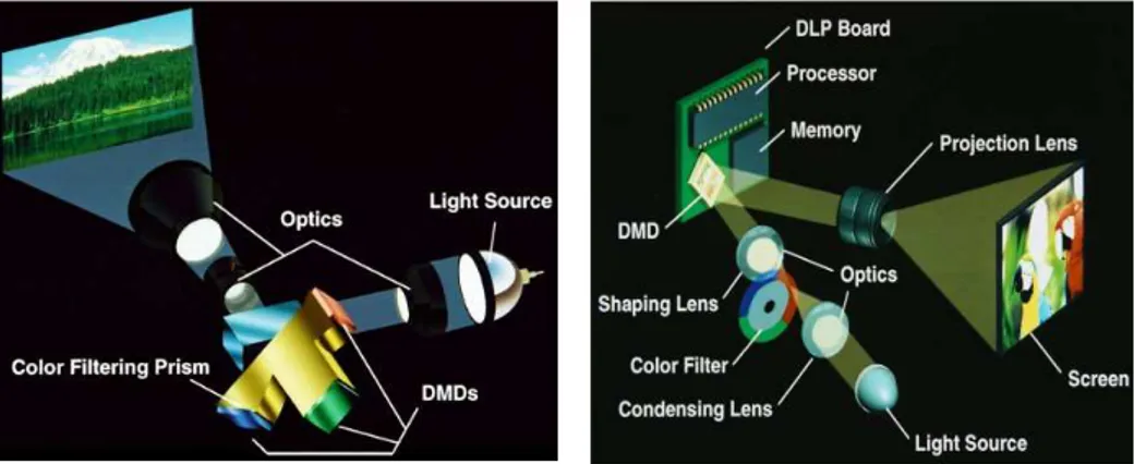
A three-chip DLP projector uses a prism to split light from the lamp, and each primary colour of light is then routed to its own DMD chip, then recombined and routed out through the lens. Three-chip DLP projectors can resolve finer gradations of shade and colour than one-chip projectors, because each colour has a longer time available to be modulated within each video frame; furthermore, there won't be any flicker or rainbow effect like with the single chip solution. Like three-tube CRT projectors, the optics for some three-chip DLP projectors must be carefully aligned. But it's more common to use a prism which makes it necessary for only one optic, instead of three, and therefore removes the problem of colour separation.
Figure 1-14 - 1-15: Triple DMD DLP projector and single DMD DLP projector.
The three-chip projectors used in movie theatres can produce 35 trillion colours, which many suggest is more than the human eye can detect. The human eye is suggested to be able to detect around 16 million colours, which is theoretically possible with the single chip solution. However, this high colour precision does not mean that DLP projectors are capable of displaying the entire gamut of colours we can distinguish (this is fundamentally impossible with any system composing colours by adding three constant base colours).
ii.
Spectrometer
A spectrometer is an optical instrument used to measure properties of light over a specific portion of the electromagnetic spectrum, typically used in spectroscopic analysis to identify materials [7]. The variable measured is most often the light's intensity but could also, for instance, be the polarization state. The independent variable is usually the wavelength of the light, normally expressed as some fraction of a meter, but sometimes expressed as some unit directly proportional to the photon energy, such as wavenumber or electron volts, which has a reciprocal relationship to wavelength. A spectrometer is used in spectroscopy for producing spectral lines and measuring their wavelengths and intensities. Spectrometer is a term that is applied to instruments that operate over a very wide range of wavelengths, from gamma rays and X-rays into the far infrared [8]. If the region of interest is restricted to near the visible spectrum, the study is called spectrophotometry.
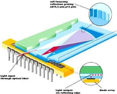
Figure 1.16: An example of MOEMS spectrometer.
By using the microspectrometer shown in figure 1-16 as key component, has been possible to develop an analytical apparatus for non-invasive, early detection of jaundice in new-born babies. After placing the hand-held device on the skin of the baby's forehead, the measuring operation starts. The instrument exposes a small area of the skin to white light and measures the specific intensity of the reflection. The concentration of bilirubin in the blood can thus be determined exactly and within a very short time. The measurement is independent of both skin colour and the exact age of the babies. An example of this instrument is shown in figure 1-17.
Figure 1-17: Non-invasive Bilirubin detector based on MOEMS spectrometer.
iii.
IR sensors
IR integrated sensors are also called InfraRed Focal Plane Array (IRFPA). IRFPAs are a subset of the active pixel sensor (APS) family. An APS is an image sensor consisting of an integrated circuit containing an array of pixel sensors, each pixel containing a photodetector and an active amplifier. There are many types of active pixel sensors including the CMOS APS used most commonly in cell phone cameras, web cameras and in some Digital Single-Lens Reflex Cameras. Such an image sensor is produced by a CMOS process (and is hence also known as a CMOS sensor), and has emerged as an alternative to charge-coupled device (CCD) imager sensors.
The term active pixel sensor was broadly defined by Eric Fossum in a 1993 paper [9].
Image sensor elements with in-pixel amplifiers were described by Noble in 1968 [10], by Chamberlain in 1969 [11], and by Weimer et al. in 1969 [12], at a time when passive-pixel sensors – that is, pixel sensors without their own amplifiers – were being investigated as a solid-state alternative to vacuum-tube imaging devices. The MOS passive-pixel sensor used just a simple switch in the pixel to read out the photodiode integrated charge [13]. The first IRFPA designs were able to operate only at cryogenic temperatures in the infrared spectrum. This devices were composed by two chip: one chip contain detector elements made of InGaAs or HgCdTe, and the other chip was typically made of silicon and was used to readout the photodetectors. The exact date of origin of these devices is classified, but they where in use from the mid 1980’s only.
Due to the very low temperature needed, these type of IRFPA never reach the consumer market nor they were investigated for large-scale application. Almost ten years ago the first prototype of uncooled IRFPA where presented giving new opportunities to the IR field of applications. Compared to cooled technology, the uncooled detector offers many interesting advantages: high reliability and lower cost, whereas the performance is high enough for a lot of applications where the “targeting” range is relatively close to the sensor (typical range around 1km). Some examples are: thermography application, automotive and military, such as thermal weapon sight and low altitude Unmanned Aerial Vehicle (UAV) detection.
Uncooled IRFPA are based on an array of MOEMS used to measure the energy of incident electromagnetic radiation. In this way it is possible to detect variation in the range of tens of milliKelvin at 60 Hz [14]. Such sensors are widely employed for thermography,
predictive maintenance, security, medical imaging, night vision, veterinarian and fire fighting. An example is shown in figure 1-18.
Figure 1-18: Using an IR sensor it is possible to detect people otherwise not visible at night.
iv.
Barcode scanner
The bar code scanners are available in various types; the basic principle of all the types is to project light to the bar code to identify the width of each bar, basing on the quantity of reflected light [15][16][17]. This bar code scanning can be done by either of the following two methods. One of the method is such that a fine beam spot is sent perpendicularly to code bars one after one and the reflected light from each bar is scanned by a single photodetector element. The other method is to projecting light evenly to the bar code surface and scanning the reflected lights from the code bars simultaneously by a photodetector or CCD (character coupled device) image sensor composed of a plural photodetector elements provided correspondingly to the code bars. In both cases an optical system is needed to handle the scanning beam or the reflected light. Due to the size reduction and high integration of this system MOEMS are the best choice for this type of optical system.
v.
Picoprojector
Today, the need for thinner TVs, portable electronics devices and more compact optical devices requires innovative optical technologies to shrink the light management module at the heart of many applications such as Rear Projection Televisions (RPTVs). Mixing MOEMS technology with solid state lighting (LEDs, HBLEDs and/or laser diodes) is a new, unique solution to achieve a potential low cost and compact light engine. The successful development of a compact and low cost light engine will improve existing products (DLPRPTV) and drive new market such as picoprojectors or smaller head-up.
The aim of picoprojectors is to realize low size, high performance portable projectors for notebooks or palm PCs and or handheld devices, such as cell phones or digital cameras [18]. This is a very promising market, as it is possible to see from the forecasts. In fact, figure 1-19 shows that the market will raise to 3720 million dollar in 2012, with a CAGR of 135%. The companies predict that the first pocket-sized projectors, available in volume within the next two years, will probably be stand-alone accessories priced at $300 to $900 (consumer price and professional price) but the ultimate goal is to fit them inside handhelds. And with camera phone owners snapping photos by the thousands (manufacturers will ship an estimated 1 billion camera phones by 2008) a built-in projector that displays photos in larger formats could be a big draw for cellular customers (figure 1-20).
0 500 1000 1500 2000 2500 3000 3500 4000 PicoProjectors forecasts 120 1520 2441 3060 3720 2008 2009 2010 2011 2012
Figure 1-19: Picoprojectors market forecasts.
However mixing solid state lighting and MOEMS require innovative solutions mixing optics, thermal management, electrical power conversion, electronic drive circuitry. Although there are many
open technical issues to be solved regarding packaging, thermal management, cost/performance ratio, green laser lifetime and market access the first picoprojectors suitable for use in a mobile phone has been demonstrated by US firm Microvision at the Global press Summit Conference in San Francisco in April 2008.
Chapter 2
T
HE
P
LATFORM
B
ASED
D
ESIGN
APPROACH
TO
A
S
ENSOR
I
NTERFACE
2.1
Introduction
Complexity of SoC (System on a Chip) design, especially in sensor interfacing and conditioning applications, has been dramatically increased over the last years thanks to recent advances in integrated technology while time-to-market requirements has strongly decreased. Cost reduction and performance enhancement of sensors are pushing the introduction of new electronic applications to an increasing variety of fields ranging from monitoring of industrial processes to automotive.
The designer of electronic devices for sensing applications has to provide complex and effective sensor interfaces in a continuously evolving and competitive market. The critical aspects that have to be overcome to achieve final success reside in facing the latest technology facilities, exploiting the recent advances for designing high performance products which combine optimal features with high reliability, answering the market craving for short time to market. A key aspect is also represented by the safety and reliability features that a platform interface has to assure and the need for flexibility to guarantee successive upgrading. The design effort for achieving an optimized sensor interface (with regard to area, performances and low power) on one side and the market aggressive demand for low cost and short development cycle on the other, has lead to a different series of approaches tailored to the specific application.
![Table 1-2: Mechanical properties of steel versus silicon [2].](https://thumb-eu.123doks.com/thumbv2/123dokorg/7533624.107337/35.892.274.688.171.601/table-mechanical-properties-steel-versus-silicon.webp)
![Figure 1-11: Sensor Systems in Automotive (source WtC) [4].](https://thumb-eu.123doks.com/thumbv2/123dokorg/7533624.107337/36.892.193.653.492.722/figure-sensor-systems-automotive-source-wtc.webp)