Electron Di
ffraction on Flash-Frozen Cowlesite Reveals the Structure
of the First Two-Dimensional Natural Zeolite
Enrico Mugnaioli, Arianna E. Lanza, Giorgio Bortolozzi, Lara Righi, Marco Merlini, Valentina Cappello,
Lara Marini, Athanassia Athanassiou, and Mauro Gemmi
*
Cite This:ACS Cent. Sci. 2020, 6, 1578−1586 Read Online
ACCESS
Metrics & More Article Recommendations*
sı Supporting InformationABSTRACT: Cowlesite, ideally Ca6Al12Si18O60·36H2O, is to date
the only natural zeolite whose structure could not be determined by X-ray methods. In this paper, we present the ab initio structure determination of this mineral obtained by three-dimensional (3D) electron diffraction data collected from single-crystal domains of a few hundreds of nanometers. The structure of cowlesite consists of an alternation of rigid zeolitic layers and low-density interlayers supported by water and cations. This makes cowlesite the only two-dimensional (2D) zeolite known in nature. When cowlesite gets in contact with a transmission electron microscope vacuum, a phase
transition to a conventional 3D zeolite framework occurs in few seconds. The original cowlesite structure could be preserved only by adopting a cryo-plunging sample preparation protocol usually employed for macromolecular samples. Such a protocol allows the investigation by 3D electron diffraction of very hydrated and very beam-sensitive inorganic materials, which were previously considered intractable by transmission electron microscopy crystallographic methods.
■
INTRODUCTIONBecause of their porous structure, zeolitesfind a wide range of applications in catalysis, ion exchange, molecular sieving, adsorption, water purification, agronomy, biomass conversion and construction.1−7They are also supposed to play a major role in future sustainable chemistry.8 Compared to other porous materials, zeolites have the remarkable advantage that their porosity is an intrinsic feature of the crystalline atomic structure. This guarantees that pores are homogeneous in the whole bulk of material, even for nanosized particles. Additionally, it is possible to build virtually infinite kinds of zeolitic structure architectures, withfinely tuned pore sizes and connectivity, and to introduce different chemically active sites in specific locations in the framework.
The term“zeolite” is classically restricted to a fully connected three-dimensional (3D) framework. Currently, there are more than 250 zeolite frameworks recognized by the International Zeolite Association (IZA).9 Nonetheless, in the last 20 years, new classes of two-dimensional (2D) porous materials have been conceived and developed, such as pillared zeolites, swollen zeolites, delaminated zeolites,10−12 and 2D carbon-silicates.13 The so-called 2D zeolites combine properties of both porous and layered materials, allowing for a wider pore size range, a larger free surface, easier accessibility to the active sites, and the possibility to introduce extra cationic species or specific organic linkers in the interlayer. Two-dimensional zeolites have extremely promising catalytic and photocatalytic proper-ties,11,14,15 despite the lower stability compared to 3D
homologues and a typical poor Al/Si ratio, generally lower than 1:10.16,17Most of 2D zeolites were accidentally discovered as intermediate or bypass products during the synthesis of conventional 3D zeolites. Other species have been obtained by postsynthesis delamination of 3D zeolites. In certain cases, it is possible to transform a 2D form into a 3D form by controlled calcination at high temperature, generally above 500°C.18
An intriguing aspect of zeolites is that their synthesis has been originally inspired by natural occurring aluminosilicate minerals, generally associated with hydrothermal alteration of magmatic rocks.1More than 70 natural zeolite species are currently known, characterized by an Al/Si ratio up to 1:1.19Hitherto, no natural 2D zeolite has been discovered, even though four families of synthetic 2D zeolites are associated with naturally occurring minerals and framework types, namely, ferrierite (FER),20 heulandite (HEU),21mutinaite (MFI),22and sodalite (SOD).23 All natural zeolites, but cowlesite, have been structurally determined by X-ray diffraction methods. Cowlesite was first reported in 1975 in several locations in the United States and Canada,24 and later discovered in other outcrops around the world.25−28This mineral has a quite constrained compositional
Received: October 28, 2019 Published: August 25, 2020
Research Article
http://pubs.acs.org/journal/acscii
copying and redistribution of the article or any adaptations for non-commercial purposes.
Downloaded via UNIV DEGLI STUDI DI SIENA on October 29, 2020 at 10:00:28 (UTC).
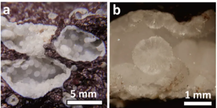
range, ideally Ca6Al12Si18O60·36H2O,26,28and typically crystal-lizes in the form of tiny platelets arranged in spherical aggregates of a few millimeters (Figures 1andS1). According to Mühe and
Stoffers,29cowlesite may be one of the main constituents of the hydroexpanded porous zones in midoceanic ridge basalts, forming during the fast cooling of pillow lavas cores. Cowlesite is indeed always recovered inside geodes in basaltic rocks that experienced fast cooling and hydrothermal alteration. Normally, the paragenesis of these geodes also comprises other zeolites, among which ferrierite and heulandite.
Despite reiterated efforts to solve the structure of this “last natural zeolite”, standard crystallographic techniques could only disclose a seemingly orthorhombic cell with approximate parameters a = 23.3, b = 30.6, and c = 25.0 Å.26No conclusive information about symmetry and atomic structure was attained. The reason for this difficulty resides in the small size of ordered cowlesite domains. Usually, even grains less than 10μm in size are polycrystalline, and therefore single-crystal X-ray diffraction results are unfeasible, even with modern synchrotron sources and apparatus. On the other hand, structure solution from powder X-ray diffraction (PXRD) is hampered by the large cell parameters and the strong peak broadening connected with the tiny and anisotropic crystal habit. Additionally, cowlesite is often associated with other nanocrystalline phases which contributeto spoiling PXRD data.
Cowlesite does not represent a unique unfortunate case. In fact, there are plenty of minerals and synthetic materials (both organic and inorganic) that do not grow into crystals large enough for X-ray single-crystal diffraction analysis. In such cases, electrons accelerated in a transmission electron microscope (TEM) have proved to be a valid option for collecting exhaustive 3D diffraction data, because they can easily be focused in a nanometric probe and have a stronger interaction with matter. In the last 10 years, electron diffraction (ED) experienced a substantial maturation connected with the introduction of 3D acquisition systems. Thefirst protocol for 3D ED was proposed in 2007.30 The introduction of more advanced acquisition strategies based on beam precession,31 beam tilt,32 or continuous sample rotation33−35 allowed structure determi-nation of a number of nanocrystalline compounds,36 among which several were minerals.37−39A decisive advantage of 3D ED is the dramatic reduction of electron dose on the sample,40 further improved by the recent development of dedicated single electron detectors.33,41 Hence, 3D ED allows acquiring exhaustive data sets from very beam sensitive materials not
investigable by high-resolution TEM imaging. Several complex natural and synthetic zeolites were structurally solved ab initio by 3D ED,42−44among which also a few 2D zeolites.45−48
In this paper, we report how 3D ED was successful in the structure determination of the supposed only structurally unknown natural zeolite to date: cowlesite. We apparently met our goal quite directly, solving ab initio a novel 3D zeolite framework, although we also observed that all our data sets where characterized by the systematic shrinkage of one cell parameter from 30.6 to 25.4 Å. Such an effect was never observed in PXRD data measured at room conditions from the same batch of material. We eventually found that the cowlesite structure is modified in the moment the sample gets in contact with the high vacuum of the TEM column (about 10−7mbar), rearranging itself in a new contracted structure after losing all or part of the structural water content.
Water loss and the consequent structural collapse could be avoided only by treating cowlesite samples with a cryo-transfer protocol, i.e., embedding the crystals in a shell of amorphous ice, which isolated the grains from the high vacuum of the TEM column. This approach is normally adopted for the structural characterization of biological macromolecules via electron crystallography33,34,49 and single-molecule cryoEM imag-ing.50,51 Thanks to this protocol, we eventually obtained 3D ED data from pristine cowlesite nanocrystals and solved their structure ab initio, discovering a unique assembly of zeolitic sheets separated by low density interlayers occupied by water and hydrated Ca-cations. Therefore, cowlesite cannot be properly assigned to the 3D zeolite mineral family, but at present constitutes the only known natural 2D zeolite.
For cowlesite, the thermally induced transition from a 2D to a 3D network is triggered at a remarkably low temperature. Such behavior could be expected for clay minerals and layered double hydroxides (LDH), but is entirely novel for a porous material. The long-waited structure disclosure of cowlesite is therefore fascinating for the design of synthetic analogues able to combine clays and zeolites properties, also considering the high Al/Si ratio of about 2:3.
■
RESULTS AND DISCUSSIONTEM and 3D ED in Vacuum. Cowlesite crystals were sampled in Montresta, Oristano Province, Sardinia (Italy). Typical cowlesite milky spherulitic aggregates were recognized inside geodes hosted in Oligo-Miocene basalts.52,53The same geodes also contain the zeolite heulandite-Ca, calcite, smectite-group minerals, analcime, chabazite-Ca, levyne-Ca, mesolite, phillipsite-Ca, stilbite-Ca, thomsonite-Ca, and tobermorite.27 TEM revealed that cowlesite crystals have a platelet-like shape, with a typical size of about 0.5−2 μm (Figures 2a and S2). Energy-dispersive X-ray (EDX) spectroscopy delivered a Ca:Al:Si ratio close to the values reported in the literature for other cowlesitefindings.
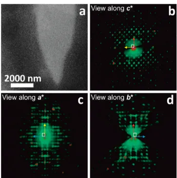
ED data, both at room temperature and after cooling the sample at 100 K inside the TEM column, systematically delivered a metrically orthorhombic C-centered unit cell with parameters a = 23.0(5), b = 24.4(5), c = 25.4(5) Å (Figure 2b−d andTable 1). Thec* direction is always orthogonal to the main platelet surface, associated with the less favored direction of growth. The 00l reflection row stands vertical when the sample is at 0° tilt and therefore falls systematically in the nonsampled missing cone for 3D ED experiments.54Moreover, a very strong diffuse scattering is observed parallel to c*, highlighting a severe stacking disorder despite the small crystal size. In fact, scanning
Figure 1.Typical occurrences of cowlesite in Montresta, Sardinia. (a) Geodes in basalts hosting cowlesite milky spherulitic aggregates. (b) Particular of a broken spherical aggregate showing the typical hedgehog-like aspect of cowlesite.
transmission electron microscopy (STEM) images show that most cowlesite crystals appear as delaminated paper reams (Figures 2a andS2). Despite the disorder, extinctions consistent with extinction symbol Cc-(ab) could be recognized in the diffraction volumes reconstructed from the best ordered 3D ED data sets (Table S1). The crystal structure wasfinally solved in the centrosymmetric space group Ccme (number 64, conven-tional setting Cmce) on the basis of 3D ED data, using direct methods implemented in SIR2014.55 All tetrahedral silicon/ aluminum positions (T) were found ab initio, together with 2 calcium positions and 30 of the 35 oxygen atoms expected in the framework.
Least-squares structure refinement, performed by SHELXL,56 converged to R1 of 0.46 after soft restraints were imposed on the geometry of the tetrahedra (Figure 3 and cif1 in SI). This relatively high value incorporates the effect of the stacking disorder and is comparable with the ones observed for other structures affected by order−disorder polytypism.37,57The
so-determined structure consists of a continuous 3D zeolite framework with no dangling bonds. However, such a framework can also be described by the union of two 2D zeolitic layers weakly connected by four pairs of Si−O−Si bridges per unit cell. Despite the apparent complexity, the structure of a single layer can be conveniently decomposed in just two independent building units (CBU), a d6r (12T) and a heavily distorted imf (16T), the latter never observed in natural zeolites. Two additional T atoms are connected with both d6r and imf and are responsible for the interlayer Si−O−Si bridging. Remarkably, the Fourier potentials associated with the two bridging T positions are significantly weaker than the other 14 T positions, a hint of positional disorder and possibly of an incomplete site occupancy.
The prominent intralayer porosity consists of an elliptical 10R channel that runs along [001], with axes of about 9 and 7 Å, respectively. Remarkably, less than 20 natural zeolites have 10R or larger channels, among them ferrierite (FER),20heulandite (HEU),21and mutinaite (MFI),22which are known to have 2D analogues.
The interlayer space is mostly occupied by a huge cavity with an oblate ellipsoid shape and axes of about 20 and 9 Å, respectively. Remarkably, this interlayer cavity alone accounts for more than 20% of the whole cell volume, i.e., about 1800 Å3.
Rounded 8R channels with a diameter of about 5 Å run along <110> and connect the interlayer cavities in a chess-board pattern, consistently with the C-centered symmetry of the lattice.
No clear atomic potential was detected by Fourier mapping inside the cavities. Nevertheless, the so-determined structure has a Ca/T ratio of 3:32, which is about half of the expected value reported in the literature and determined by EDX on the very same crystals from where 3D ED data were collected. Also, no water or hydroxyl group could be confidently located. We therefore must assume that part of the water and the remaining Ca atoms get heavily disordered after the vacuum-triggered structure collapse, and, possibly, partially leak from the framework.
3D ED Investigation of the Frozen-Hydrated Samples. The shrinkage and partial rearrangement of the cowlesite structure is likely connected with the removal of structural water by the vacuum of the TEM column. A similar behavior was already reported for the minerals kaňkite58
and cyanotrichite,59 where water molecules hold a pivotal structural role. The fast transformation imposed by the TEM vacuum prevented us from studying the native cowlesite structure by 3D ED, even after sample cooling and after adopting ultrafast acquisition protocols that minimize beam-induced amorphization.35,40
We therefore prepared cowlesite samples by a cryo-plunging procedure, up to now applied only to biological33,34,49−51and small-molecule organic samples.60Thanks to this protocol, the cowlesite nanocrystals were embedded in amorphous ice, which
Figure 2. Dehydrated cowlesite obtained after a few seconds of exposure to the TEM vacuum. (a) STEM image of a typical grain, made of stacked and partially delaminated layers. (b) Projection of the reconstructed 3D ED data alongc*, showing the chess-board extinction due to the C-centered lattice. (c) Projection of the reconstructed 3D ED data alonga*, showing the strong diffuse scattering along c* and the extinctions hk0: k = 2n due to the b-glide plane. (d) Projection of the reconstructed 3D ED data alongb*, showing diffuse scattering along c* and extinctions hk0: h = 2n due to the a-glide plane. Extinctions 0kl: l = 2n, related with the c-glide plane orthogonal toa*, are only partially sampled in this data set. The unit cell is sketched in white. Red arrow points towarda*; yellow arrow points toward b*; blue arrow points towardc*.
Table 1. Comparison of Cell Parameters of Different Forms of Cowlesite, Measured by 3D ED and PXRD Respectively
dehydrated, RT vacuum frozen-hydrated,−173 °C pristine, RT dehydrated, 165°C dehydrated, RT after 1 month
method 3D ED 3D ED PXRD PXRD PXRD
a/Å 23.0(5) 23.0(5) 23.116(8) 23.16(1) 23.18(1)
b/Å 24.4(5) 24.8(5) 24.891(7) 24.77(1) 24.88(2)
c/Å 25.4(5) 30.1(6) 30.468(2) 25.586(3) 26.397(6)
sealed the porosity avoiding the direct exposure of the mineral to the vacuum and the consequent water loss.
ED data recorded from frozen-hydrated crystals delivered a C-centered orthorhombic cell with parameters a = 23.0(5), b = 24.8(5), c = 30.1(6) Å (Figure 4,Table 1, andTable S1). These values are in better agreement with the PXRD measurements performed on natural samples at room conditions. The accuracy of cell parameters was anyway reduced by the pervasive diffuse
scattering parallel to the c* direction, which is remarkably intense also for the cryo-protected sample and therefore probably a primary feature of cowlesite nanocrystals.
Structure solution was again obtained ab initio in space group Ccme on the basis of 3D ED data collected from single sub-micrometric crystals. Two Ca positions, all T positions, and 35 over 36 O atoms were clearly spotted ab initio. The structure consists of zeolitic layers parallel to (001) separated by low-density interlayers of about 5.5 Å in thickness. The internal topology of zeolitic layers is identical to the one observed in the vacuum-shrunk structure, but they are alternately shifted alonga of about 8 Å.
In the structure obtained from the cryo-protected sample, two relatively weak potential peaks occupy the low-density interlayer. These peaks are located at distances of about 1.8− 2.2 Å from the dangling oxygen atoms of the zeolitic layers, the same atoms that bridge the structure in the dehydrated form. When these positions are interpreted as Ca atoms, the Ca/T ratio becomes 6:32, now in good agreement with the expected cowlesite composition (Figure 5andcif2 in SI).
With the available data, we could not pursue the location of the water molecules expected in the structure. The pervasive diffuse scattering significantly reduces the quality of 3D ED intensity data. We infer that at least part of the water molecules connect to the Ca atoms forming hydrated Ca(O,H2O)x coordination polyhedra, as observed for other layered hydrated minerals with conspicuous swelling properties, like vermic-ulite.61
Figure 3.Structure of dehydrated cowlesite viewed along the three main crystallographic directions. Si/Al tetrahedra are colored in yellow, O atoms in red, and Ca atoms in blue. Tetrahedra form a fully connected 3D zeolitic framework, but alongcdense layers are loosely connected by low density layers located at z = 0 and 1/2.
Figure 4. Cryo-protected cowlesite preserving the native cell parameters. (a) STEM image of a typical grain embedded in amorphous ice. 3D ED data were actually collected only from the tip of this grain. (b) Projection of the reconstructed 3D ED data alongc*, showing the chess-board extinction due to the C-centered lattice. (c) Projection of the reconstructed 3D ED data alonga*, showing diffuse scattering alongb* and c* and extinctions hk0: k = 2n due to the b-glide plane. (d) Projection of the reconstructed 3D ED data alongb*, showing diffuse scattering alonga* and c* and extinctions hk0: h = 2n due to the a-glide plane. The unit cell is sketched in white. Red arrow points towarda*; yellow arrow points towardb*; blue arrow points toward c*.
If we assume that most of the interlayer atoms are gathered around the dangling T positions, the interlayer space is occupied by scalene cavities with axes of about 15, 13, and 9 Å (volume of 900 Å3). In total, the interlayer free space accounts again for
about 20% of the whole cell volume. The 10R intralayer channels are now not perfectly aligned but still allow cavity interconnection along [001]. Connection along [010] is instead
guaranteed by channels of about 8 Å in diameter located in the interlayer.
Thermal Analyses and in Situ Powder X-ray Di ffrac-tion. Thermogravimetry/differential scanning calorimetry (TGA/DSC) and in situ PXRD were performed to track and better define the transition of cowlesite from a 2D structure to a fully connected 3D tetrahedral network. TGA shows that in N2 atmosphere cowlesite undergoes a continuous loss of weight upon heating, from room temperature up to 300°C. Two main inflections are at about 92 °C and at about 228 °C (Figure S3). DSC shows two endothermic processes (Figure S4). Heat exchange occurs from room temperature and culminates in a first peak located at about 138 °C. A second broader peak is located at about 269°C (Figure S4). We interpret this evidence as a continuous loss of loosely bonded water from a cowlesite interlayer, which eventually destabilizes the Ca-rich interlayer and triggers the phase transition toward a 3D zeolitic framework around 138°C at ambient pressure. The ex-situ PXRD pattern acquired after heating at 230 °C still corresponds to the dehydrated phase (Figure S5). Later, the structure of cowlesite loses all residual water molecules, possibly structurally connected with the framework or trapped inside the zeolitic channels. This is likely the cause for a gradual amorphization of the material. In the ex-situ PXRD pattern of the sample heated up to 400°C for 15 min (Figure S5), the peak positions still correspond to the dehydrated phase, but we observe an overall weakening of the diffraction and the complete disappearance of some classes of reflections (including 00l). The thermal behavior of cowlesite is similar to the ones reported for other natural Ca-hosting zeolites with large-cavities, like gismondine, chabazite, and mordenite.62 Highly hydrated phyllosilicates, such as montmorillonite and bentonite, also show typical TGA inflections around 100 °C.
In-situ variable-temperature PXRD was performed on a cowlesite sample pretreated at reduced pressure and heated at 5 °C min−1. Despite the poor diffracting power of our sample, the
in situ PXRD analysis showed a very sharp phase transition at 125°C upon heating (Figure 6). This transition corresponds to the change from the hydrated to the dehydrated cowlesite forms and occurs at a remarkably low temperature compared to typical transition from 2D to 3D zeolites.18This fact can be rationalized by noting that, according to the stoichiometry and structural model of cowlesite, the 2D to 3D structural transition requires merely the loss of water and no other more energy-intensive processes, such as de-hydroxylation.
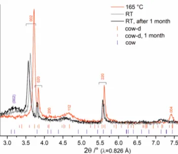
The dehydrated sample was then cooled down at ambient temperature. A general expansion of the lattice was observed, but the hydrated phase was not restored. However, the peak shift and decay along with the growth of a broad band at d≈ 15 Å suggest that dehydrated cowlesite is unstable and that a slow partial rehydration occurs even at mild ambient humidity. The steady growth of an amorphous phase was also evidenced by the PXRD pattern measured on the same sample after one month (Figure 7andTable 1).
Incidentally, the d-spacings of the strongest diffraction peaks of dehydrated cowlesite are compatible with the still unidentified impurity phase found by Vezzalini et al. in one of their cowlesite samples.26
Order−Disorder Description of Cowlesite System. Cowlesite is characterized by a structurally anisotropic structure, with very weak connections between zeolitic layers piled along the direction c. The cowlesite structure can be conveniently
Figure 5.Structure of cryo-protected cowlesite along the three main crystallographic directions. Si/Al tetrahedra are colored in yellow, O atoms in red, and Ca atoms in blue. Zeolitic layers parallel to (001) are separated by low density layers hosting partially disordered calcium ions and, supposedly, water molecules.
modeled by the order−disorder (OD) theory,63 assuming a basic layer (a, b, c/2) with layer symmetry C2m(a).
The groupoid family symbol is therefore
{ } C m a n 2 ( ) 2 (2 ) r,2 r 2
The ordered cowlesite structure determined experimentally by cryo-plunging 3D ED corresponds to the maximum degree of order (MDO) sequence, with r = 2. This means that cowlesite layers are all equivalent, and each following layer is obtained applying a rotation ofπ around c.
A reduction of symmetry, for example, connected with vacancies in the interlayer, may bring different polymorphs. Additionally, in the cryo-transfer experiments, we also detected a recurrent C-centered monoclinic polymorph with parameters a = 23.8(5), b = 25.8(5), c = 15.9(3) Å,β = 99.5°, and space group Cm (Figure S6). Its structure, partially solved on the basis of 3D ED data, corresponds to another polytype that can be obtained starting from the same basic layer (a, b, c/2) and applying the groupoid family symbol:
{ − }
C m a n n
2 ( )
2g 2,g ( g r, 1)
with r = 2 and g≈ −2/9. The coexistence of the two polymorphs in the same cowlesite nanograin may be concealed by the diffuse scattering connected with the general stacking disorder along the directionc.
■
CONCLUSIONSCowlesite is an intriguing crystallographic case both for its peculiar and unique structural features, and for the combination of low dose 3D ED methods and the cryoEM sample preparation protocol required for its structure determination. Because of the small size of its coherent crystalline domains, cowlesite is the only natural zeolite whose structure could not be determined by X-ray diffraction methods. Using 3D electron diffraction, we were able to determine ab initio the structure of cowlesite and to reveal that it consists of alternated rigid zeolitic layers and weak interlayers supported by water and Ca ions. Such mechanical anisotropy favors the frequent occurrence of stacking defects parallel to (001), as normally expected for clays and other layered materials.
In cowlesite, rigid 2D zeolitic layers are loosely connected by water and Ca ions, similarly to what happens in well-known expandable minerals like vermiculite. This makes cowlesite the only 2D zeolite mineral hitherto known and explains its properties, at the same time typical of zeolites and clays. Additionally, when cowlesite is exposed to a high vacuum or is heated at a temperature just above 100°C, its structure shows a very peculiar behavior, rearranging into a proper 3D zeolitic framework kept together by unique Si−O−Si bridging groups.
During dehydration, Ca atoms move to disordered positions, possibly confined within the large interlayer cavity. Such a dehydrated form appears unstable at room condition, probably due to the uptake of water from the natural environment.
At present, cowlesite is the only 2D zeolite that is naturally occurring and stable at Earth surface conditions, the only 2D zeolite with a very high Al/Si ratio of about 2:3, and the only one that can be transformed in a 3D derivate at low temperature (or even at room temperature when confined in vacuum). These features make cowlesite a very interesting starting point for the development of naturally inspired materials, which at the same time encourages mineralogists to search for zeolitic phases with the same layered character, possibly related to the specific
Figure 6.(a) Evolution of the PXRD pattern with temperature; (b) indexing of the hydrated (cow) and dehydrated (cow-d) phases.
Figure 7.Comparison of the PXRD pattern of the dehydrated phase at 165°C (red), the same sample after cooling down to room temperature (gray) and after standing 1 month at room conditions (black).
geologic environment occurring during crustal expansion along midoceanic ridges.
The method employed for solving the cowlesite crystal structure is a combination of state-of-the-art 3D ED and cryoEM sample preparation protocols, applied for the first time to an inorganic hydrated sample. Cowlesite diffraction data were collected with a low-dose protocol, which combined STEM imaging for crystal tracking and nanobeam electron diffraction. Weak reflections, partially shaded by diffuse scattering, were efficiently recorded by a single-electron detector of new generation. However, the vacuum inside the TEM column causes the water supported interlayer to collapse and induces a transition to a standard 3D zeolite framework. We were able to preserve the pristine structure of cowlesite only applying a cryo-plunging protocol similar to the one used for biological samples, and recently proposed also for the analysis of pharmaceuticals. The cryo-protection given by a shell of amorphous ice prevents any water diffusion toward the external surface of the crystals and maintains the layered structure intact. The structure determination of cowlesite proves that cryo-plunging protocols can also be applied for the 3D electron diffraction analysis of very hydrated inorganic materials, which were previously supposed to be intractable by crystallographic TEM methods. The same procedure couldfind interesting application in the cases of host/guest structures, where molecules are trapped inside a framework, but their loose bonding causes them to move through the structure. The cryo-protection could therefore allow the location of guest molecules ordering inside the pores of a material in its native state, overcoming the perturbation induced by the low pressure of the TEM column.
■
MATERIALS AND METHODSTEM and 3D Electron Diffraction Analysis. For standard observations at room temperature, cowlesite aggregates were gently crushed and deposited directly on copper grids coated with continuous carbonfilm (EMS) without any dispersion in liquid. For cryo-protected samples, the same grids were treated before deposition with an oxygen plasma cleaner for 30 s at 20 W, and they were used within 1 h to maintain a stable hydrophilicity. Cryo-plunging was done using a Leica EM GP apparatus. The environmental chamber was set to 20°C and 50% relative humidity. A droplet of 5μL of cowlesite powder dispersed in distilled water was loaded directly in the cryo-camera. The grids were blotted for 2 s and plunge-frozen into liquid ethane at a temperature of−180 ± 3 °C.
Scanning transmission electron microscopy (STEM) imaging and 3D ED data were acquired with a Zeiss Libra 120 TEM operating at 120 kV and equipped with a LaB6source. 3D ED was performed in STEM mode after defocusing the beam in order to have a pseudoparallel illumination on the sample, as described in Lanza et al.49 A beam size of about 150 nm in diameter was obtained by inserting a 5 μm C2 condenser aperture. An extremely low dose illumination was used in order to limit beam-induced amorphization of the sample. For a complete review of experimental 3D ED protocols, see Gemmi et al.36and Gemmi & Lanza.40
Both continuous and precession-assisted stepwise 3D ED data sets were collected. The data sets used for thefinal refinement were acquired in a stepwise mode with an angular step of 1° and total tilt ranges up to 120°. After each tilt, a diffraction pattern was acquired, and the crystal position was tracked by defocused STEM imaging. During the experiment, the beam was precessed around the optical axis by an angle of 1°, as first described by
Mugnaioli et al.31Precession was obtained using a Nanomegas Digistar P1000 device. Diffraction patterns at room temperature were recorded by a TRS 16 bit CCD (2k× 2k), while diffraction patterns of the cryo-protected sample were recorded by an ASI Timepix single-electron camera.33 Acquisitions for cryo-protected samples were done at about−173 °C by a GATAN 626 cryo-holder.
3D ED data were analyzed using the software PETS64 and ADT3D.54Ab-initio structure determination was obtained by standard direct methods as implemented in the software SIR2014.55 Data were treated with a fully kinematical approximation, i.e., neglecting dynamical scattering and assuming that Ihkl was proportional to |Fhkl|2. Least-squares
structure refinement was performed with the software SHELXL.56
Powder X-ray Diffraction. In-situ powder X-ray diffraction (PXRD) data were collected as a function of temperature at the MCX beamline of the Italian ELETTRA synchrotron, set at 15 keV (0.826 Å) with a parallel beam of 1 mm× 0.3 mm and a scintillator detector.65,66A 0.3 mm capillary containing Silicon standard powder (NIST 640c) was measured in the range 0− 50° for line profile and wavelength calibration.
Ground cowlesite from Montresta was loaded in a 0.3 mm borosilicate glass capillary, pretreated at reduced pressure with a membrane pump (0.160 bar) for 45 min, and then sealed with a flame. The sample was heated with a gas blower from 25 to 165 °C, at the rate of 5 °C min−1in steps of 10°C. After each heating
ramp, the temperature was kept constant, and a short PXRD pattern was acquired in the range 2.2−6° 2θ, with a step size of 0.008° 2θ in continuous scan and using 2 s exposure time per step. A set of 15 patterns were acquired with this experimental setup.
Moreover, complete PXRD patterns from cowlesite were acquired in the range 2−40° 2θ, with a constant step size of 0.008° 2θ and 2 s exposure time per step. Data were collected (i) at 21°C on the pristine sample, (ii) at 165 °C on the dehydrated sample, (iii) again at room temperature on the thermally treated sample immediately after the cooling, and (iv) at room temperature on the thermally treated sample after 1 month. Indexing and Pawleyfitting were performed with GSAS-II.67
Finally, two cowlesite samples were heated in an oven to 230 and 400 °C at 5 °C min−1 and maintained at the final temperatures for 15 min. Immediately after the thermal treatment, the powders were loaded in 0.3 mm borosilicate glass capillaries for ex-situ PXRD characterization. The PXRD patterns were acquired in Debye−Scherrer geometry with Cu− Kα1 radiation on a STOE Stadi P powder diffractometer equipped with a Johansson monochromator and a MYTHEN linear position sensitive detector.
Thermogravimetry and Differential Scanning Calo-rimetry. Thermogravimetric analysis was performed with a TA-Instruments TGA Q500 in the range 30−800 °C while heating the sample at 5 °C min−1 in N2 atmosphere. Differential scanning calorimetry was performed with a TA-Instruments Discovery DSC 250 in the range 30−400 °C, while heating the sample at 5°C min−1in N2atmosphere.
In all experiments performed, no unexpected or unusually high safety hazards were encountered.
■
ASSOCIATED CONTENT*
sı Supporting Information. The Supporting Information is available free of charge at
Optical pictures of cowlesite samples. Stem images of cowlesite nanocrystals. DSC and TGA data. Powder X-ray diffraction patterns of cowlesite after thermal treatments. 3D ED of a cowlesite polymorph with monoclinic cell. Structural and experimental data of the structure determination of cowlesite (PDF)
Crystallographic informationfile 1 (CIF) Crystallographic informationfile 2 (CIF)
■
AUTHOR INFORMATIONCorresponding Author
Mauro Gemmi − Center for Nanotechnology Innovation@NEST, Istituto Italiano di Tecnologia, 56127 Pisa, Italy; orcid.org/
0000-0001-9542-3783; Email:[email protected]
Authors
Enrico Mugnaioli − Center for Nanotechnology Innovation@ NEST, Istituto Italiano di Tecnologia, 56127 Pisa, Italy Arianna E. Lanza − Center for Nanotechnology Innovation@
NEST, Istituto Italiano di Tecnologia, 56127 Pisa, Italy;
orcid.org/0000-0002-7820-907X
Giorgio Bortolozzi − Associazione Micromineralogica Italiana (AMI), 26100 Cremona, Italy
Lara Righi − Department of Chemistry, Life Sciences and Environmental Sustainability, University of Parma, Parma 43124, Italy; IMEM-CNR, 43123 Parma, Italy
Marco Merlini − Dipartimento di Scienze della Terra, Università degli Studi di Milano, 20133 Milano, Italy
Valentina Cappello − Center for Nanotechnology Innovation@ NEST, Istituto Italiano di Tecnologia, 56127 Pisa, Italy Lara Marini − Smart Materials, Istituto Italiano di Tecnologia,
16163 Genova, Italy
Athanassia Athanassiou − Smart Materials, Istituto Italiano di Tecnologia, 16163 Genova, Italy; orcid.org/0000-0002-6533-3231
Complete contact information is available at:
https://pubs.acs.org/10.1021/acscentsci.9b01100 Notes
The authors declare no competingfinancial interest.
■
ACKNOWLEDGMENTSThe authors acknowledge the Regione Toscana for funding the purchase of the Timepix detector through the FELIX project (Por CREO FESR 2014-2020 action).
■
REFERENCES(1) Mumpton, F. A. La roca magica: Uses of natural zeolites in agriculture and industry. Proc. Natl. Acad. Sci. U. S. A. 1999, 96, 3463− 3470.
(2) Caro, J; Noack, M; Kolsch, P; Schafer, R Zeolite membranes− state of their development and perspective. Microporous Mesoporous Mater. 2000, 38, 3−24.
(3) Davis, M. E. Ordered porous materials for emerging applications. Nature 2002, 417, 813−821.
(4) Corma, A. State of the art and future challenges of zeolites as catalysts. J. Catal. 2003, 216, 298−312.
(5) Tosheva, L.; Valtchev, V. P. Nanozeolites: Synthesis, Crystal-lization Mechanism, and Applications. Chem. Mater. 2005, 17, 2494− 2513.
(6) Morris, R. E.; Wheatley, P. S. Gas Storage in Nanoporous Materials. Angew. Chem., Int. Ed. 2008, 47, 4966−4981.
(7) Primo, A.; Garcia, H. Zeolites as catalysts in oil refining. Chem. Soc. Rev. 2014, 43, 7548−7561.
(8) Li, Y.; Li, L.; Yu, J. Applications of Zeolites in Sustainable. Chemistry. Chem. 2017, 3, 928−949.
(9) Baerlocher, C.; McCusker, L. B. Database of Zeolite Structures: http://www.iza-structure.org/databases/, 1996.
(10) Corma, A.; Fornes, V.; Pergher, S. B.; Maesen, T. L. M.; Buglass, J. G. Delaminated zeolite precursors as selective acidic catalysts. Nature 1998, 396, 353−356.
(11) Corma, A.; Diaz, U.; Domine, M. E.; Fornés, V. New Aluminosilicate and Titanosilicate Delaminated Materials Active for Acid Catalysis, and Oxidation Reactions Using H2O2. J. Am. Chem. Soc. 2000, 122, 2804−2809.
(12) Roth, W. J.; Čejka, J.; Millini, R.; Montanari, E.; Gil, B.; Kubu, M. Swelling and Interlayer Chemistry of Layered MWW Zeolites MCM-22 and MCM-56 with High Al Content. Chem. Mater. 2015, 27, 4620− 4629.
(13) Bellussi, G.; Carati, A.; Di Paola, E.; Millini, R.; Parker, W. O., Jr.; Rizzo, C.; Zanardi, S. Crystalline hybrid organic−inorganic alumino-silicates. Microporous Mesoporous Mater. 2008, 113, 252−260.
(14) Opanasenko, M. V.; Roth, W. J.; Čejka, J. Two-dimensional zeolites in catalysis: current status and perspectives. Catal. Sci. Technol. 2016, 6, 2467−2484.
(15) Emdadi, L.; Tran, D. T.; Zhang, J.; Wu, W.; Song, H.; Gan, Q.; Liu, D. Synthesis of titanosilicate pillared MFI zeolite as an efficient photocatalyst. RSC Adv. 2017, 7, 3249−3256.
(16) Bellussi, G.; Carati, A.; Rizzo, C.; Millini, R. New trends in the synthesis of crystalline microporous materials. Catal. Sci. Technol. 2013, 3, 833−857.
(17) Roth, W. J.; Nachtigall, P.; Morris, R. E.; Čejka, J. Two-Dimensional Zeolites: Current Status and Perspectives. Chem. Rev. 2014, 114, 4807−4837.
(18) Lawton, S. L.; Fung, A. S.; Kennedy, G. J.; Alemany, L. B.; Chang, C. D.; Hatzikos, G. H.; Lissy, D. N.; Rubin, M. K.; Timken, H. C.; Steuernagel, S.; Woessner, D. E. Zeolite MCM-49: A Three-Dimensional MCM-22 Analogue Synthesized by in Situ Crystallization. J. Phys. Chem. 1996, 100, 3788−3798.
(19) Wise, W. S.; Tschernich, R. W. Habits, crystal forms and composition of thomsonite. Can. Mineral. 1976, 16, 487−493.
(20) Schreyeck, L.; Caullet, P.; Mougenel, J. C.; Guth, J. L.; Marler, B. PREFER: a new layered (alumino) silicate precursor of FER-type zeolite. Microporous Mater. 1996, 6, 259−271.
(21) Gies, H.; Müller, H.; Yilmaz, B.; Tatsumi, T.; Xie, B.; Xiao, F.; Bao, X.; Zhang, W.; De Vos, D. Interlayer Expansion of the Layered Zeolite Precursor RUB-39: A Universal Method To Synthesize Functionalized Microporous Silicates. Chem. Mater. 2011, 23, 2545− 2554.
(22) Choi, M.; Na, K.; Kim, J.; Sakamoto, Y.; Terasaki, O.; Ryoo, R. Stable single-unit-cell nanosheets of zeolite MFI as active and long-lived catalysts. Nature 2009, 461, 246−249.
(23) Oberhagemann, U.; Bayat, P.; Marler, B.; Gies, H.; Rius, J. A Layer Silicate: Synthesis and Structure of the Zeolite Precursor RUB-15-[N(CH3)4]8[Si24O52(OH)4]•20H2O. Angew. Chem., Int. Ed. Engl. 1996, 35, 2869−2872.
(24) Wise, W. S.; Tschernich, R. W. Cowlesite, a New Ca-Zeolite. Am. Mineral. 1975, 60, 951−956.
(25) Nawaz, R. New data on cowlesite from Northern Ireland. Mineral. Mag. 1984, 48, 565−566.
(26) Vezzalini, G.; Artioli, G.; Quartieri, S.; Foy, H. The crystal chemistry of cowlesite. Mineral. Mag. 1992, 56, 575−579.
(27) Bortolozzi, G.; Ciriotti, M. E.; Galli, E.; Bonacina, E. Carlhintzeite e cowlesite della Sardegna: primi ritrovamenti italiani. MICRO 2007, 33−37.
(28) Kol’tsova, T. N. Compositions of Gismondine, Cymrite, Anorthite, and Celsian Solid Solutions. Inorg. Mater. 2017, 53, 741− 751.
(29) Mühe, R.; Stoffers, P. Rock structures and mineral assemblage associated with hydroexpansion in mid-oceanic ridge basalts. Mineral. Petrol. 1995, 54, 71−83.
(30) Kolb, U.; Gorelik, T.; Kübel, C.; Otten, M. T.; Hubert, D. Towards automated diffraction tomography: Part IData acquisition. Ultramicroscopy 2007, 107, 507−513.
(31) Mugnaioli, E.; Gorelik, T.; Kolb, U.‘‘Ab initio’’ structure solution from electron diffraction data obtained by a combination of automated diffraction tomography and precession technique. Ultramicroscopy 2009, 109, 758−765.
(32) Zhang, D.; Oleynikov, P.; Hovmöller, S.; Zou, X. Collecting 3D electron diffraction data by the rotation method. Z. Kristallogr. 2010, 225, 94−102.
(33) Nederlof, I.; van Genderen, E.; Li, Y.; Abrahams, J. P. A Medipix quantum area detector allows rotation electron diffraction data collection from submicrometre three-dimensional protein crystals. Acta Crystallogr., Sect. D: Biol. Crystallogr. 2013, 69, 1223−1230.
(34) Nannenga, B. L.; Shi, D.; Leslie, A. G. W.; Gonen, T. High-resolution structure determination by continuous-rotation data collection in MicroED. Nat. Methods 2014, 11, 927−930.
(35) Gemmi, M.; La Placa, M. G. I.; Galanis, A. S.; Rauch, E. F.; Nicolopoulos, S. Fast electron diffraction tomography. J. Appl. Crystallogr. 2015, 48, 718−727.
(36) Gemmi, M.; Mugnaioli, E.; Gorelik, T. E.; Kolb, U.; Palatinus, L.; Boullay, P.; Hovmöller, S.; Abrahams, J. P. 3D electron diffraction: the nanocrystallography revolution. ACS Cent. Sci. 2019, 5, 1315−1329.
(37) Rozhdestvenskaya, I. V.; Mugnaioli, E.; Schowalter, M.; Schmidt, M. U.; Czank, M.; Depmeier, W.; Rosenauer, A. The structure of denisovite, a fibrous nanocrystalline polytypic disordered ‘very complex’ silicate, studied by a synergistic multi-disciplinary approach employing methods of electron crystallography and X-ray powder diffraction. IUCrJ 2017, 4, 223−242.
(38) Mugnaioli, E.; Gemmi, M. Single-crystal analysis of nanodomains by electron diffraction tomography: mineralogy at the order-disorder borderline. Z. Kristallogr. - Cryst. Mater. 2018, 233, 163−178.
(39) Lanza, A. E.; Gemmi, M.; Bindi, L.; Mugnaioli, E.; Paar, W. H. Daliranite, PbHgAs2S5: determination of the incommensurately modulated structure and revision of the chemical formula. Acta Crystallogr., Sect. B: Struct. Sci., Cryst. Eng. Mater. 2019, 75, 711−716.
(40) Gemmi, M.; Lanza, A. E. 3D electron diffraction techniques. Acta Crystallogr., Sect. B: Struct. Sci., Cryst. Eng. Mater. 2019, 75, 495−504.
(41) Tinti, G.; Fröjdh, E.; van Genderen, E.; Gruene, T.; Schmitt, B.; de Winter, D. A. M.; Weckhuysen, B. M.; Abrahams, J. P. Electron crystallography with the EIGER detector. IUCrJ 2018, 5, 190−199.
(42) Jiang, J.; Jorda, J. L.; Yu, J.; Baumes, L. A.; Mugnaioli, E.; Diaz-Cabanas, M. J.; Kolb, U.; Corma, A. Synthesis and Structure Determination of the Hierarchical Meso-Microporous Zeolite ITQ-43. Science 2011, 333, 1131−1134.
(43) Guo, P.; Shin, J.; Greenaway, A. G.; Min, J. G.; Su, J.; Choi, H. J.; Liu, L.; Cox, P. A.; Hong, S. B.; Wright, P. A.; Zou, X. A zeolite family with expanding structural complexity and embedded isoreticular structures. Nature 2015, 524, 74−78.
(44) Simancas, J.; Simancas, R.; Bereciartua, P. J.; Jorda, J. L.; Rey, F.; Corma, A.; Nicolopoulos, S.; Das, P. P.; Gemmi, M.; Mugnaioli, E. Ultrafast Electron Diffraction Tomography for Structure Determi-nation of the New Zeolite ITQ-58. J. Am. Chem. Soc. 2016, 138, 10116− 10119.
(45) Bellussi, G.; Montanari, E.; Di Paola, E.; Millini, R.; Carati, A.; Rizzo, C.; O'Neil Parker, W.; Gemmi, M.; Mugnaioli, E.; Kolb, U.; Zanardi, S. ECS-3: A Crystalline Hybrid Organic−Inorganic Alumi-nosilicate with Open Porosity. Angew. Chem., Int. Ed. 2012, 51, 666− 669.
(46) Arletti, R.; Mugnaioli, E.; Kolb, U.; Di Renzo, F. MZ-35, a new layered pentasil borosilicate synthesized in the presence of large alkali cations. Microporous Mesoporous Mater. 2014, 189, 64−70.
(47) Guo, P.; Liu, L.; Yun, Y.; Su, J.; Wan, W.; Gies, H.; Zhang, H.; Xiao, F.-S.; Zou, X. Ab initio structure determination of interlayer expanded zeolites by single crystal rotation electron diffraction. Dalton Trans. 2014, 43, 10593.
(48) Sun, Q.; Ma, Y.; Wang, N.; Li, X.; Xi, D.; Xu, J.; Deng, F.; Yoon, K. B.; Oleynikov, P.; Terasaki, O.; Yu, J. High performance nanosheet-like silicoaluminophosphate molecular sieves: synthesis, 3D EDT
structural analysis and MTO catalytic studies. J. Mater. Chem. A 2014, 2, 17828−17839.
(49) Lanza, A.; Margheritis, E.; Mugnaioli, E.; Cappello, V.; Garau, G.; Gemmi, M. Nanobeam precession-assisted 3D electron diffraction reveals a new polymorph of hen egg-white lysozyme. IUCrJ 2019, 6, 178−188.
(50) Cheng, Y. Single-particle cryo-EM at crystallographic resolution. Cell 2015, 161, 450−457.
(51) Merk, A.; Bartesaghi, A.; Banerjee, S.; Falconieri, V.; Rao, P.; Davis, M. I.; Pragani, R.; Boxer, M. B.; Earl, L. A.; Milne, J. L. S.; Subramaniam, S. Breaking Cryo-EM Resolution Barriers to Facilitate Drug Discovery. Cell 2016, 165, 1698−1707.
(52) Morra, V.; Secchi, F. A. G.; Melluso, L.; Franciosi, L. High-Mg subduction-related Tertiary basalts in Sardinia, Italy. Lithos 1997, 40, 69−91.
(53) Lustrino, M.; Fedele, L.; Melluso, L.; Morra, V.; Ronga, F.; Geldmacher, J.; Duggen, S.; Agostini, S.; Cucciniello, C.; Franciosi, L.; Meisel, T. Origin and evolution of Cenozoic magmatism of Sardinia (Italy). A combined isotopic (Sr−Nd−Pb−O−Hf−Os) and petro-logical view. Lithos 2013, 180−181, 138−158.
(54) Mugnaioli, E.; Kolb, U. Structure characterization of nano-crystalline porous materials by tomographic electron diffraction. Z. Kristallogr. - Cryst. Mater. 2015, 230, 271−288.
(55) Burla, M. C.; Caliandro, R.; Carrozzini, B.; Cascarano, G. L.; Cuocci, C.; Giacovazzo, C.; Mallamo, M.; Mazzone, A.; Polidori, G. Crystal structure determination and refinement via SIR2014. J. Appl. Crystallogr. 2015, 48, 306−309.
(56) Sheldrick, G. M. A short history of SHELX. Acta Crystallogr., Sect. A: Found. Crystallogr. 2008, 64, 112−122.
(57) Mugnaioli, E.; Gorelik, T. E. Structure analysis of materials at the order−disorder borderline using three-dimensional electron diffrac-tion. Acta Crystallogr., Sect. B: Struct. Sci., Cryst. Eng. Mater. 2019, 75, 550−563.
(58) Majzlan, J.; Palatinus, L.; Plášil, J. Crystal structure of Fe2(AsO4)(HAsO4)(OH)(H2O)3, a dehydration product of kaňkite. Eur. J. Mineral. 2016, 28, 63−70.
(59) Ventruti, G.; Mugnaioli, E.; Capitani, G.; Scordari, F.; Pinto, D.; Lausi, A. A structural study of cyanotrichite from Dachang by conventional and automated electron diffraction. Phys. Chem. Miner. 2015, 42, 651−661.
(60) Jones, C. G.; Martynowycz, M. W.; Hattne, J.; Fulton, T. J.; Stoltz, B. M.; Rodriguez, J. A.; Nelson, H. M.; Gonen, T. The CryoEM Method MicroED as a Powerful Tool for Small Molecule Structure Determination. ACS Cent. Sci. 2018, 4, 1587−1592.
(61) Arguelles, A.; Leoni, M.; Blanco, J. A.; Marcos, C. Semi-ordered crystalline structure of the Santa Olalla vermiculite inferred from X-ray powder diffraction. Am. Mineral. 2010, 95, 126−134.
(62) van Reeuwijk, L. P. The Thermal Dehydration of Natural Zeolites; Veenman: Wageningen 1974.
(63) Dornberger-Schiff, K.; Fichtner, K. On the Symmetry of OD-Structures Consisting of Equivalent Layers. Krist. Tech. 1972, 7, 1035− 1056.
(64) Palatinus, L.; Brázda, P.; Jelínek, M.; Hrdá, J.; Steciuk, G.; Klementova, M. Specifics of the data processing of precession electron diffraction tomography data and their implementation in the program PETS2.0. Acta Crystallogr., Sect. B: Struct. Sci., Cryst. Eng. Mater. 2019, 75, 512−522.
(65) Rebuffi, L.; Plaisier, J. R.; Abdellatief, M.; Lausi, A.; Scardi, P. MCX: A synchrotron radiation beamline for X-ray diffraction line profile analysis. Z. Anorg. Allg. Chem. 2014, 640, 3100−3106.
(66) Plaisier, J. R.; Nodari, L.; Gigli, L.; Rebollo San Miguel, E. P.; Bertoncello, R.; Lausi, A. The X-ray diffraction beamline MCX at Elettra: a case study of non-destructive analysis on stained glass. Acta IMEKO 2017, 6, 71−75.
(67) Toby, B. H.; Von Dreele, R. B. GSAS-II: the genesis of a modern open-source all purpose crystallography software package. J. Appl. Crystallogr. 2013, 46, 544−549.