PhD Thesis
Robotic disassembly for the
Circular Economy
PhD student: ANNAGIULIA MORACHIOLI SUPERVISOR: PROF. PAOLO DARIO TUTOR: PROF. FABIO BONSIGNORIO
1
2
TABLE OF CONTENTS
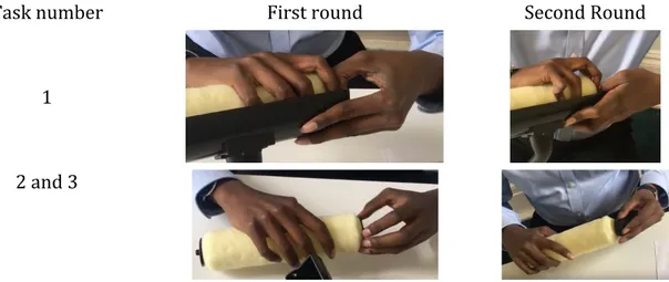
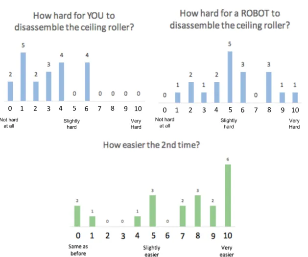
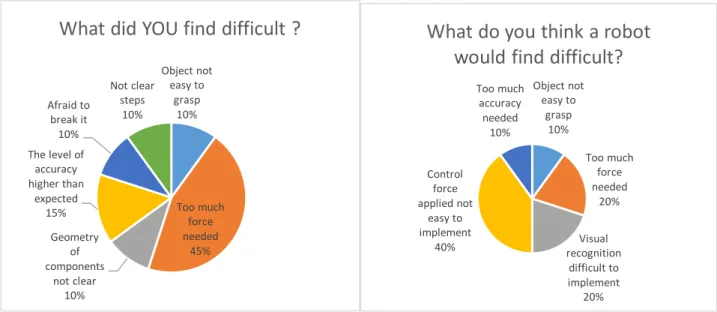
TABLE OF CONTENTS ... 2 1. Introduction ... 5 2. Robotics in the Circular Economy ... 7 2.1 Circular Economy ... 7 2.2 Disassembly ... 9 2.2.1 The role of disassembly study in the Circular Economy paradigm ... 10 2.2.2 The disassembly problem ... 11 2.2.3 A new paradigm: the peg-out-of-hole ... 11 2.3 Design for Disassembly ... 13 2.3.1 The disassemblability of products ... 15 2.3.2 Guidelines for Design for Disassembly ... 16 2.4 Robotic Disassembly ... 23 2.5 References ... 25 3. Dependability ... 27 3.1 Intro on dependability ... 27 3.2 Attributes of dependability ... 29 3.2.1 Reliability ... 30 3.2.2 Availability ... 31 3.2.3 Maintainability ... 32 3.2.4 Safety ... 33 3.2.5 Integrity ... 34 3.2.6 Confidentiality ... 34 3.2.7 Secondary attributes: robustness and security ... 34 3.2.7.1 Robustness ... 35 3.2.7.2 Security ... 35 3.3 Threats to dependability ... 36 3.4 Means to dependability ... 37 3.5 References ... 39 4. Manipulation and Grasping ... 40 4.1 Related Literature ... 40 4.2 Artificial Hands for Human-Like Grasping ... 41 4.3 Robotic hands ... 43 4.4 Dual-Arm Robot for Human-Like Manipulation ... 45 4.5 References ... 50 5. Human-inspired model of bimanual dexterous manipulation ... 57 5.1 Preliminary case study: disassembly of a car suspension by skilled and non-skilled technicians 57 5.1.1 Deconstructing the daily working life activities of manual workers in mechanical parts disassembly tasks ... 573 5.1.2 The protocol ... 58 5.1.3 Methods ... 59 5.1.4 Results ... 60 5.1.5 Discussion ... 64 5.2 The bimanual dexterous manipulation model ... 66 5.2.1 Characterization of high-level manipulation ... 66 5.2.2 Characterization of low-level hand configurations ... 68 5.2.3 Bimanual dexterous manipulation characterization ... 71 5.2.4 Discussion ... 72 5.3 Second case study: disassembly of three objects ... 73 5.3.1 Rationale and summary of methods ... 73 5.3.2 How to map the data ... 75 5.3.3 Ceiling roller ... 75 5.3.3.1 Dismantling instructions ... 76 5.3.3.2 Results ... 76 5.3.3.3 Repetition of the experiment ... 78 5.3.3.4 Questionnaire on the execution of the disassembly of the ceiling roller ... 81 5.3.4 Pencil sharpener ... 85 5.3.4.1 Dismantling instructions ... 85 5.3.4.2 Results ... 85 5.3.4.3 Repetition of the experiment ... 88 5.3.4.4 Questionnaire on the execution of the disassembly of the pencil sharpener ... 93 5.3.5 Portable Vacuum Cleaner ... 98 5.3.5.1 Dismantling instructions ... 98 5.3.5.2 Results ... 99 5.3.5.3 Repetition of the experiment ... 102 5.3.5.4 Questionnaire on the execution of the disassembly of the portable vacuum cleaner ... 106 5.3.6 Analysis of human performances when disassembly objects: a benchmark for robotic applications’ dependability ... 110 5.3.6.1 Ceiling roller ... 111 5.3.6.2 Pencil sharpener ... 112 5.3.6.3 Portable Vacuum Cleaner ... 114 5.3.7 Discussion ... 115 5.4 References ... 119 6. The Robotic Cases Studies ... 120 6.1 Set up of the robotic system ... 120 6.2 System Architecture: Visual Servoing Coordinated Bimanual Manipulation ... 123 6.2.1 Visual Servoing ... 124 6.2.2 Task and Motion Planning ... 126 6.2.3 Force Control ... 127 6.3 Robotic Experiments ... 128 6.3.1 First Implemented Solution: Pick-and-Place of Delicate Objects in Unstructured Environment 128 6.3.1.1 Experimental Set up ... 129 6.3.1.2 Experimental Results ... 131 6.3.1.3 Discussions ... 135 6.3.2 Second Implemented Solution: Robotic Unscrew ... 136
4 6.3.2.1 Motion in Unstructured Environment and Pick-and-Place of Objects ... 136 6.3.2.2 Disassembly Task Performed in Unstructured Environment ... 140 6.3.2.3 Prototypical Final Scenario ... 146 6.3.2.4 Discussions ... 150 6.4 References ... 152 7. Conclusions ... 154 8. List of Publications ... 156 9. Acknowledgments ... 157
5
1. Introduction
This work presents the first results on the development of novel robotic dual-arm vision and sensor guided disassembly methods and practical systems for the Circular Economy. The starting point and the basis of this research is the in-depth analysis of the human manipulation task execution behaviours when disassembling objects of increasing complexity. Our study aims, among other objectives, to show by evidence how the much-needed transition to the Circular Economy paradigm, whose disassembly is one of the main processes, is now technically and economically viable and to provide the basis for some initial concrete guidelines for the development of robotic disassembly.
Beginning from the analysis of the manipulation and grasping taxonomies already proposed in the literature and that can be found in the state of the art, the feasibility of the implementation of human-inspired disassembly robotic procedures has been empirically
verified by means of our first bimanual dexterous robot experimental model. The model is
human-inspired and provides a complete description of the set of grasping and manipulation combinations when developing disassembly tasks, in terms of both hand function and hand configuration. It can be applied to one-hand and to bimanual manipulation operations to comply with all different tasks of a specific application. As such, it represents the first model of human bimanual dexterous manipulation. The model is empirically grounded and results from a study of twenty participants performing non-destructive disassembly of three different objects (a ceiling roller, a pencil sharpener and a portable vacuum cleaner). Human performances in executing the disassembly of the objects have been analysed and the bimanual grasp and manipulation combinations that led to a successful disassembly mapped into the newly developed model. The mapped results constitute a base empirical ground for the development of novel effective and efficient bioinspired robotic disassembly strategies. It has
been already used as a tool to define algorithms allowing the implementation of some robotic
disassembly task. The model itself could easily be applied to any other application and also to human behavioural studies.
The analysis of human behaviours – on top of its per se scientific interest - allows to define a set of objective performance benchmarks to assess the quality and in particular the
dependability of disassembly tasks when performed by robots. Dependability, meant as the level of trust that we can rely on the capability of a robotic platform to perform the tasks for which it has been designed, is the study at the basis of the introduction of a new technological process such as the automated disassembly. Such human performances have also been analysed in terms of “failed attempts”, defined as the manipulation combinations that did not led to a successful disassembly. We believe that such analysis could serve as a benchmark for dependability assessments of robotic platforms implementing the same task and a first preliminary analysis is reported.
Participants were requested to complete a set of questionnaires to provide their perception in terms of complexity when disassembling the objects, and also estimate the difficulties of a potential robotic platform performing the same tasks. Such analysis might be of interest for further AI and Machine Learning studies. A subset of participants having a background in
6
industrial design also provided an initial feedback in terms of optimized Design for Disassembly. The performance model, being by itself a guideline for robotics implementation of human and robotic disassembly, is intended to be also a tool to compare and evaluate different grippers as well as robotic platforms and motion planning algorithms. Further research will focus on introducing haptic information on objects that have reached their End of Life and consider how their compromised status affects the disassembly process, also from a design for robotic disassembly perspective.
Disassembly tasks have been implemented and tested on a bimanual robotic platform as
well. The hardware platform utilized to test the control algorithms and perform the experimental tests integrates the SMART5 RML Comau Dual-Arm anthropomorphic robot on a TCP-IP network with a vision system that guided its actions (visual servoing), torque sensing and control and that can be easily expanded to various governing. The system was able to
perform preliminary disassembly tasks in a semi-structured work environment implementing a set of complex coordinated operations, such as unscrewing a mechanical piece from its site. A preliminary comparison of human and robot performances when implementing the unscrewing operations is provided in order to assess the reliability of such initial robotic set up.
In Chapter 1 an introduction on the goals, and motivations of the research and its methods and tools are introduced.
In Chapter 2 the Circular Economy’s main concepts and one of its bottleneck processes, disassembly, are discussed in the perspective of their robotization and automation. A new paradigm is also introduced, the peg-out-of-hole problem, and a set of guidelines for Design for Disassembly provided.
In Chapter 3 manipulation and grasping notions are exploited, focusing on artificial hands and dual-arm robotic platform.
Chapter 4 provides the state of the art of Dependability of robotic platforms and set the basis to analyse the performance of a new robotic set up (Chapter 6) compared to human performances (Chapter 5).
Chapter 5 describes the first human-inspired model of bimanual dexterous manipulation for disassembly tasks. Preliminary studies are shown, and an innovative bimanual dexterous manipulation model described. Two case studies are analysed: a disassembly of a car suspension by skilled and non-skilled technicians and the disassembly of three objects and the consequential mapping of their data on the bimanual model.
In Chapter 6 an example of bimanual coordinated manipulation using a Dual-Arm robot, on the basis of the arguments introduced in Chapter 3, is presented. We developed an experimental setup that was able to recognize different object put on a work table (using a 3D vision system), to choose which object to operate on (realization of task planning algorithms) and to perform disassembly operations on the chosen object, adopting both robotic arms in cooperating bimanual manipulation. The robotic performances are analysed based on the notion gained in Chapter 3 and compared to the human ones shown in Chapter 5.
In Chapter 7, the Conclusions and future developments are discussed, while Chapter 8 is for additional reference.
2. Robotics in the Circular Economy
The Circular Economy (CE) paradigm advocates a shift away from the linear model of production, consumption, and disposal towards one that reduces waste and improves resource productivity. The automation of the processes of this novel paradigm requires robotic systems able to dismantle diverse objects. A key application in CE is disassembly, which, together with recycling, could become fundamental in a CE paradigm and in a society like ours, which is increasingly concerned about the ecological and economic implications of manufacturing. In order to implement robotic disassembly processes studies on different fields have to be implemented in parallel such as: dual-arm manipulation, robotic platforms, Design for Disassembly. The background reported in this section support the analysis of Chapter 5 and Chapter 6, in which disassembly tasks are implemented by humans and robotic platform.
2.1 Circular Economy
Circular Economy (CE) is defined as a method of economic development based on ecological circulation of natural materials and artefacts (see Fig. 1) [1]. The origin of the term is not certain. Already in 1848, Hofman, the first President of the Royal Society of Chemistry, stated “.. in an ideal chemical factory there is, strictly speaking, no waste but only products. The better a real factory makes use of its waste, the closer it gets to its ideal, the bigger is the profit” [2].CE, through its paradigm of ‘reduce-reuse-recycle’, represents an alternative to the actual paradigm of the ‘Linear Economy’, defined as ‘take-make-dispose’ economy, who has been relying on the inputs of cheap and available resources.
Figure 1. Circular Economy Conceptual Scheme [1].
The concept of a Circular Economy [3][4]has its conceptual roots in industrial ecology, which envisions a form of material symbiosis between otherwise very different companies and
8 production processes. Industrial ecology emphasizes the benefits of recycling residual waste materials through, for example, the development of complex inter-linkages, such as those in the renowned industrial symbiosis projects [5]. In general, the final aim is to minimize the use of resources and push the adoption of cleaner technologies [6][7]. In industrial ecology, it is implied that a Circular Economy will be not only beneficial to society but to the economy as a whole as well. The minimization of the use of environment has to be implemented both in using it as sink for residuals but also as a source of virgin materials.
Even though in the past two decades many countries, as well as emerging ones, had made impressive progresses in environmental sustainability, the global trends of production, consumption and trade are still dangerously unsustainable. The knowledge that resource efficiency and security are critical to future economic is increasing. This leads to the fundamental requirement of rethink on the role and function of resources in the economy. According to McKinsey [8],cheap resources reinforced economic growth for great part of the 20th century, but in the last eight years prices have raised back to heights not seen since the 1900s and still they are estimated to remain high for at least the next 20 years. To overcome this new resource price reality, new forms of value creation must be developed if the world is to maintain and increase a new quality of prosperity. Strong trends indicate that the linear model is towards its ends [1]: - In present manufacturing processes, there are still opportunities to increase efficiency but gains are largely incremental thus insufficient to create a competitive advantage or differentiation
- Eco-efficiency had unforeseen consequences in accelerating energy use and resource depletion thus increase in the real amounts of materials and energy used
- Agricultural productivity is actually growing more slowly than expected while in parallel soil fertility and nutritional value of foods are declining.
When eliminating waste from industrial chain and reuse materials as much as possible, increases production savings and obtains less resource dependence. Benefits are not only operational but also strategic. Circular Economy is intended to be a driver for innovation, job creation, improved land productivity and soil health, nevertheless, long-term resilience for the economy.
The nation that has most fully embraced the implementation of CE concepts is China [9] but the concept is gradually becoming an idea accepted by some industries and policymakers within Europe which aim at keeping resources in economic use for as long as possible (see Fig. 2).
9
Figure 2. Recycling in Europe.
Economic and technological resources are arising in this field and it is clear that something needs to change. In [10] evidence that resources are finite are reported. D. Meadow et al [11] is sure that we are using materials in a rate that we cannot replace and different researches states that climate change is definitely influencing such issues [12]. As a consequence, business models will have to change and any initiative in such direction is welcome. Only manufacturing generates an excess of 60% of annual non- hazardous waste [13]. Finally, new strict legal requirements arose and demand a reduction in the environmental impacts of products and manufacturing processes. Such measures and the increasing competition of the global industrial activity, push companies to modify their approach towards product design. Companies are pushed to design products in order to last long time and to have materials easy to recover when they reach the end of life. As a consequence, they should realize that processing used products has indeed a business potential [14]. Remanufacturing a disassembled product is preferable to recycling since its value is increased by returning waste products to working order, while recycling simply reduces the used product to its raw material value. In the latest year, recycling has seen an increase in its activity but still the amount of solid waste is considerable. Landfills are full of and serious pollution and occupational health problems caused. One of the main activity that generates a huge amount of solid waste is the disposal of household appliances.
The dismantling of products appears to be one of the most serious problems.
2.2 Disassembly
A key application in CE is disassembly, which, together with recycling, could become fundamental in a CE paradigm and in a society like ours, which is increasingly concerned about
10 the ecological and economic implications of manufacturing. Robotics applications in assembly are based on robotics and automated solutions, which are well-known and widely applied in modern industry. The study of disassembly implies several fundamental distinctions compared to assembly tasks. A crucial difference is that in disassembly processes objects have a past ‘life’, which most probably had modified them both in their aspect and in their internal structure. What is even more crucial is that objects at the end of their life have changed in a unpredictable way, which might not be the same as for another same object. As a consequence, a disassembly system typically deals with unstructured environments characterized by a much higher degree of uncertainty than for assembly tasks. A general characteristic of a disassembly system should be the one to be able to properly and correctly understand several aspects of the world and be able to deal with more complex tasks efficiently [3].
2.2.1 The role of disassembly study in the Circular Economy
paradigm
Given the sustainability challenges we are facing as a society, in which ecological and economic implications of manufacturing are becoming of great concern, disassembly and recycling are becoming fundamental factors. The input of having cheap and always-available resources pushed today’s ‘take-make-dispose’ economy to create conditions for growth and stability. Within the past decade, however, businesses actually increased their product prices and erased the decline of the entire preceding century. In addition to this, three billion more middle-class consumers are expected by 2030. Such unexpected rise in demand for a finite supply of resources requires redefining our current predominantly linear economic system. Without a proper rework on how to use materials in the current linear ‘take-make-dispose’ economy, elements such as gold, iridium, indium, silver, tungsten and many others fundamental for industry could be exhausted within five to fifty years.
By saving in materials, the economic gain is expected to be at over a trillion dollars a year. Job creation might significantly increase through a shift to innovative processes as reusing, remanufacturing and recycling products. Only in EU, 500,000 jobs are created by the recycling industry [1].
Assembly has raised as a concept since the beginning of the Industrial Revolution in the last half of the XVIII century. The economic driving forces for manufacturing goods in large quantities and at low cost have stimulated the implementation of automated machines and processes for assembly tasks. Nowadays new priorities arose which are in contrast with the past ones and more related to the concept of environmental consciousness in manufacturing and, even more, to the concept of disassembly, and to such tasks as dismantling and recycling. At present time, a new concept is introduced, the one of “inverse” factory, intended as a system that closes the loop production cycle (design-assembly-use). The inverse factory leads to the full implementation of the concept of “integrated design”, in which products are conceived not only to be assembled and used, but also to be totally and efficiently disassembled and recycled [3].
11
Robotics applications in dismantling are based on well-known automation solutions which are applied in modern industry robotics. “Robotized dismantling” can be defined as the reversed process of robotized manufacturing. As in assembly, the robotic platform would replace human labor in repeatable operations during dismantling process. A dismantling process could be organized in a form of de-manufacturing line, equipped with robotized tools, in which each step is performed in order to dismantle and recover resources. Due to the speed of robots, their capability in being highly repeatable and precise in positioning, it is realistic to think that robotized disassembly unit will be small but able to process large quantities of waste [13].
2.2.2 The disassembly problem
The process of disassembly applied in the robotic field shows several fundamental distinctions compared to assembly tasks [9]. As mentioned before, a crucial difference is that in disassembly problems objects have a past “life” which had modified their structure. As a consequence, an ideal disassembly system should have the capacity to deal with unstructured environments having a higher degree of uncertainty than for assembly tasks. Integrated design represents a powerful tool for reducing such uncertainty: a product properly designed could easily be inserted in an automated system for disassembly which could operates in a partially structured environment. At present time, the state-of-the-art of the artificial perception in industrial settings is not innovative enough to allow the transition to a disassembly system [3]. For this reason, the few existing approaches to robotic disassembly use a large a priori knowledge of the environment allowing them to operate with a certain degree of uncertainty.
The main issue when dealing with disassembly on a small scale, indeed, is the one of perception. In fact, artificial perception has not the capability yet to replicate biological performances within a short time [5]. In [5] they present the development of a robotic system for disassembly automation integrated of different sensory modalities (vision and touch).
Assembly and Disassembly problems are tightly related to four more specific and limited problems, which can be solved if solutions to the Assembly Path Planning (APP) and Disassembly Path Planning (DAPP) are found [15]. These problems are Motion Stability, Assembly Maintainability, Selective Disassembly Planning, and Partitioning. Among these problems, only the Motion Stability Problem is related to both APP and DAPP problems, and the others are closely related only to the DAPP problem.
2.2.3 A new paradigm: the peg-out-of-hole
Being one of the most repeated task in assembly industry, mating a peg into a hole can be considered as one of the most classic problem in robotics. This operation presents numerous well-known issues extensively researched since it requires a manipulation controlled both in position and force. The earliest work of automated assembling processes started at 1950s in the field of military electronics equipment [16]. At that time, the objective was to standardize the parts interfaces in order to be assembled with pre-programmed productions lines and
12
reduce costs and time. In the following years, many assembling lines in which the location of parts and system behaviour are well known and have been fully automated. Still, many assembling tasks, such as the assembling of car doors or electronic connectors in the automotive industry are still carried by human operators. In the last years, the research on the
automated peg-in-hole assembling, which addresses the mentioned non-automated tasks,
gained the interest by many researchers again. This is could be mainly because of the development in the technologies of industrial robots and sensors systems. Different approaches were investigated to guide the industrial robot using sensors.
The operation of the peg-in-hole has always been fundamental in any application and for any human operator, but is surprisingly difficult to have it carried out by a robot manipulator [17]. Despite of the efforts and many proposed solution, it is hard to find an implemented fully automated assembling approach in today’s industry for many peg-in-hole scenarios, as reported in [18]. The reason is partly due to a physical limitation of the mechanical compliance of the robot wrist and arm and partly to a lack of a mating strategy [17]. In addition, the uncertainties in work environment increase the complexity in executing the task [18].
Different approaches were investigated to guide the industrial robot using sensors.
The initial concentration was on pegs of circular cross-section. The major contributions of Whitney and Asada assumed chamfered holes. Whitney [19] segregated the assembly process into four parts: chamfer crossing, single-point contact, two-point contact and insertion (see Fig. 3) [20].
In the insertion phase, two situations could arise when a peg get stuck a: jamming and wedging. Jamming happens when forces and moments are wrongly applied to the peg through the support, and wedging because of linear dependency of the resultant forces at the constraints [17].
Figure 3. Peg-in-hole mating stages.
As the assembly operations can be summarized using the paradigm of the peg-in-hole, symmetrically, the disassembly operations have here been summarized in a new paradigm, that for intuitiveness is called peg-out-of-hole, to outline the necessity of decoupling diverse parts that compose the same object (see Fig. 4). In this study, it is claimed that the peg-out-of-hole is the model for representing the disassembly operations and represents a new paradigm.
13
Figure 4. Examples of peg-out-of hole: (top) separate; (bottom) unscrew.
The peg-out-of-hole is the study of two synergic movements: separate and unscrew two (or more) parts of an object and it schematizes the fundamental operations used in disassembly a complex object. The main operations can be grouped in two principal categories:
• Separate: pull out, unstick, unplug, detach, … • Unscrew.
The resulting movement of the peg-out-of-hole technique will be relative to the specific disassembly situation.
2.3 Design for Disassembly
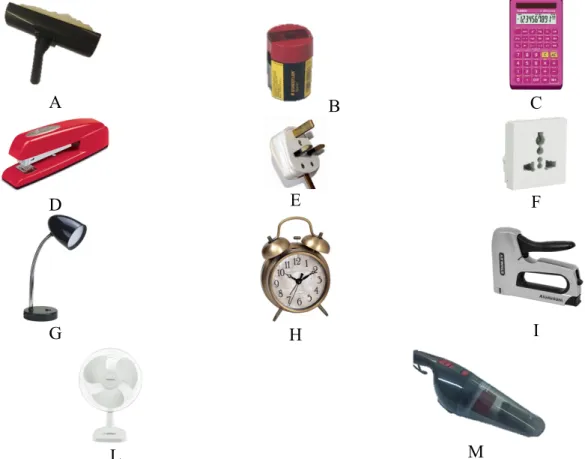
In engineering, disassembly can be defined as the process that takes apart a systematically assembled product (which actually is an assembly of components). The reasons to disassembly a product might be different, such as empower maintenance, improve serviceability and/or to affect end-of-life (EOL) objectives such as product reuse, remanufacture and recycling [21]. The matter is that nowadays, our products are not designed in order to be easily dismantled or disassembled. By implementing integrated design, using specific fastening and assembly principles and surface coatings, for example, can influence the level of complexity when disassembling the product and separating materials into non-contaminated groups. Product specifications represent the basis for a proper design.Disassembly requirements are expected to influence production methods and processes. However, much effort is needed to structure the field and develop Design for Disassembly (DfD) methods, but awareness of the problems will speed up the process and has already led to improved designs [13]. DfD has mainly influence on recyclability and having the opportunity to have easy disassembly makes it possible to re-use, remanufacture and recycle materials in an efficient manner. Fig. 5 shows the process of recycling two or more materials.
14
Figure 5. Recycling cycle of two or more materials [13].
The table below shows the number of steps required for each combination shown in Fig. 5. By knowing that product recyclability is increased when materials are compatible with fixings/attachments, when having incompatible materials, non-dismountable surface attachments and the number of steps required for recycling increase dramatically. The result is that the process is both costly and resource-intensive. 2 Steps to Recyclability 3 Steps to Recyclability 4 Steps to Recyclability 5 Steps to Recyclability 6 Steps to Recyclability Not Recyclable A-C A-D-G B-F-I A-D-H-M B-F-J-N
A-D-H-L-P B-F-J-O-R-T A-D-H-K
B-E B-F-J-O-Q
Table 1. Number of steps of recyclability for each combination of Fig. 3.
The shortest “path” towards material recycling is one of the first objective, and this is largely dependent by the material compatibility. With “material compatibility” is intended the similarity in the chemical structures of the materials which needs to be broken down into their raw form together.
DfD has the purpose to make these activities easier and more economical as it will define a process in which it is easier to separate materials into groups without contamination. But still much research has to be carried out focusing on the properties of recycled materials [13]. The
15 role played by economic factors in the determination of an optimal recycling and disassembly strategy is illustrated in Fig. 6.
Figure 6. Optimal recycling and disassembly strategy [13].
Usually manufacturers distinguish disassembly in two categories based on the method of disassembly [21]:
• Destructive disassembly: it is obtained mainly through the application of brute force, e.g. incineration, metal cutting, etc.
• Non-destructive disassembly or reverse-assembly: no brute force is applied but components just separated from the assemblies. Based on the extent of the process of disassembly, non-destructive disassembly can be further categorised into two groups as follows: • Total disassembly: the whole product is disassembled into its main components. Such process is sometimes not economically feasible due to cost effective parameters such as time, economic factors, presence of hazardous materials, etc. • Selective/partial disassembly: it is intended as a reversible dismantling of a complex product into less complex subassemblies or single components. It consists of a systematic removal of the components from an assembly while ensuring that there is no impairment of parts due to the process. In this study, the attention is on non-destructive disassembly processes that can be both total or selective/partial.
2.3.1 The disassemblability of products
With “disassemblability of a product” is intended “the degree of easy disassembly” [22]. The following factors have been identified to affect disassemblability: • Use of force: minimal use of force is recommended. As a consequence, the disassembly process should carried-out quickly without the use of excessive manual labor16 • Mechanism of disassembly: a simple one is always preferable • Use of tools: ideally, disassembly should take place without the use of tools. Minimize the number of tools is good practice. • Repetition of parts: part repetition should be minimized in order to have a quick and easy identification of parts at each stage of the process • Easy identification of disassembly points: disassembly points are defined as those joints, which need to be disjointed so as to affect disassembly. Easy recognisability of such points is preferable, especially when dealing with complex product structures or products that incorporate snap fits as well as in the case of products that accumulate internal dirt during their useful life • Product structure: a simpler product structure, a better disassembly process and gain in terms of costs (in terms of time and labor) • Use of toxic materials: it is desirable not to incorporate toxic materials in the design of parts since most disassembly is still manual and they may pose health hazards to the operator performing the disassembly. Even in the automated scenario, human operators could support the robot to execute some tasks thus such hazard should be removed. When designing a product having the perspective of Design for Disassembly, several changes may be incorporated. This may include redesigning components, standardizing parts, materials and subassemblies, devising innovative joining methods etc.
Thus, the following parameters have been addressed in [21] in order to evaluate the disassemblability of a product:
1. Components and fasteners level of accessibility: is preferable to have an easy access in order to have a quick and efficient disassembly operation.
2. Amount of force required for separating components: the lesser the amount of force required, the faster the process and the better the design.
3. Positioning: the amount of precision required to place a tool for disassembly purposes has to be defined. The greater the degree of accuracy required, the more the time. 4. Requirements of tools: in ideal disassembly condition the process should have easy
grasp in order to manipulate the object and remove it without the exertion of much force and without the use of any tools. However, in most cases, product disassembly requires the use of common tools such as hammer, screwdriver, clamp etc.
2.3.2 Guidelines for Design for Disassembly
Design for Disassembly processes has the purpose to correctly identify design specifications that minimize the complexity of the product structure [21]. This can be achieved through numerous steps such as optimization of parts, utilization of common materials, optimize spatial alignment between various components to favour disassembly without jeopardizing assemblability, functionality and structural soundness.Design for Disassembly is very similar to design for assembly. Basic guidelines are given in Table 2.
17
The general idea is that a product that has an easy assembling design, should also be easily disassembled. However, there are some major differences: for example, in snap-fit design (integral fasteners), extra care is needed for remanufacturing. On the other hand, if a part is intended for material recycling only, then the disassembly methods typically require tearing apart the assembled connections, and so the disassembly times are completely different from the assembly ones. Further, what must be disassembled is not the same as what must be assembled, since some subassemblies may not worth disassembling or might be made of compatible materials.
18 Guideline Don’t Do Use attachment that are easy to disassemble
Minimize the number of fasteners
Use the same fastener
Ensure easy access for disassembly Use simple standard tools Avoid long disassembly paths
Design for damage free disassembly
Use the same tool for assembly and disassembly
Use one disassembly
direction to avoid
reorientation
Design for multiple
detachments with one
operation
Table 2. Mechanical joints suitable for disassembly [32].
Over the years, guidelines have been developed starting from Design for Assembly ones (i.e.: minimize the joint number, see Table 2), and specific ones have been developed too (i.e. plastic-to-plastic joints specific guidelines, see Table 3).
19 Type Disassembly method Snap fit Snapped out Press fit Ripped out Pressed out Screw Unscrewed Screw insert Unscrewed chiselled off Rolled in Cut of at arrow area Press fit Ripped out Pressed out Drilled out Stud welded Chiseled off Milled away Molded in (outsert) Economically not feasible Glue bond Economically not feasible Tape weld Apply electric control
Table 3. Plastic-to-plastic joint design guideline (GE, 1995).
By analizing [14][22][23]- [26], a final set of Design for Disassembly Guidelines has been summarized. Such rules have been obtained starting from Design for Assembly Guidelines, since how a product is assembled influences how it is disassembled. The provided set of guidelines has been divided into three macro areas: Design, Fasteners and Materials, see Table 4.
20 DESIGN GUIDELINES Simplify and standardize the design and reduce the number of parts
Avoid the components to move with each other when possible
Minimize the number of components different with each other. Repetition of parts: should be minimized to enable quick and easy identification of parts at each stage of disassembly
Integrate components (which relate to the same function) where possible Make components easily separable Avoid small holes Minimize the number and length of interconnecting wires or cables used Standard gripping spots should be put near center of gravity Enable simultaneous separation and disassembly
Avoid necessity for simultaneous disassembly at different joining elements Avoid long disassembly paths Use common tools Avoid undercuts which require special operations & tools Design work pieces to use standard cutters, drill bit sizes or other tools Mistake-proof product design and easy handling
Components should be designed so that they can only be disassembled in one way, not reverse
Product design must avoid parts which can become tangled, wedged or disoriented. Avoid holes and tabs and designed "closed" parts. avoid parts with sharp edges, burrs or point Part design should incorporate symmetry around both axes of insertion wherever possible
Parts should be designed having surfaces that are easy to grasp, place and fixture. Ideally this means flat, parallel surfaces that would allow a part to picked-up by a person or a gripper with a pick-and-place robot
Minimize thin, flat parts that are more difficult to pick up. Avoid very small parts that are difficult to pick-up or require a tool such as tweezers to pick up
Avoid parts that are sticky or slippery Avoid parts that are sticky or slippery
Avoid hardened or difficult machined materials unless essential to requirements
21
Open access and visibility at separation points are preferred Design the work station area
to minimize the distance to access and move part
Positioning: degree of precision is required to place the tool or hand properly
Design modular products to facilitate disassembly
Modular design principles allow for greater flexibility during product development, shorter development timescales and reduced development costs.
In case of Robotic Disassembly
Involve less flexibility than manual production
Design parts to utilize standard gripper and avoid gripper/tool change Use self-locating parts Use simple parts presentation devices Avoid the need to secure or clamp parts Use a minimum of parts or standard parts for minimum of feeding bowls Use closed parts (no holes or slots or projections) to avoid tangling Take into count the magnitude of manual force required to effect disassembly. minimal use FASTENERS GUIDELINES Simplify and standardize the fasteners Minimise the number of fasteners Minimise the types of fasteners Standardise the fasteners used Use fasteners that are easy to remove Use snap-fits where possible Use common tools Minimise the number of fastener removal tools needed Mistake-proof product design and easy handling Fastening points have to be easy to access Design related Design for efficient joining and fastening, threaded fasteners
(screws, bolts, nuts and washers) are time-consuming to assemble and difficult to automate. Standardize to minimize variety and use fasteners such as self-threading screws and captured washers. Consider the use of integral attachment methods (snap-fit). Evaluate other bonding with adhesives.
MATERIALS GUIDELINES Choose material based on
efficient joining and fastening
Consider work-hardening, fracture, fatigue failure and general wear when designing snap-fits
If metallic fasteners are used, then ferrous types are
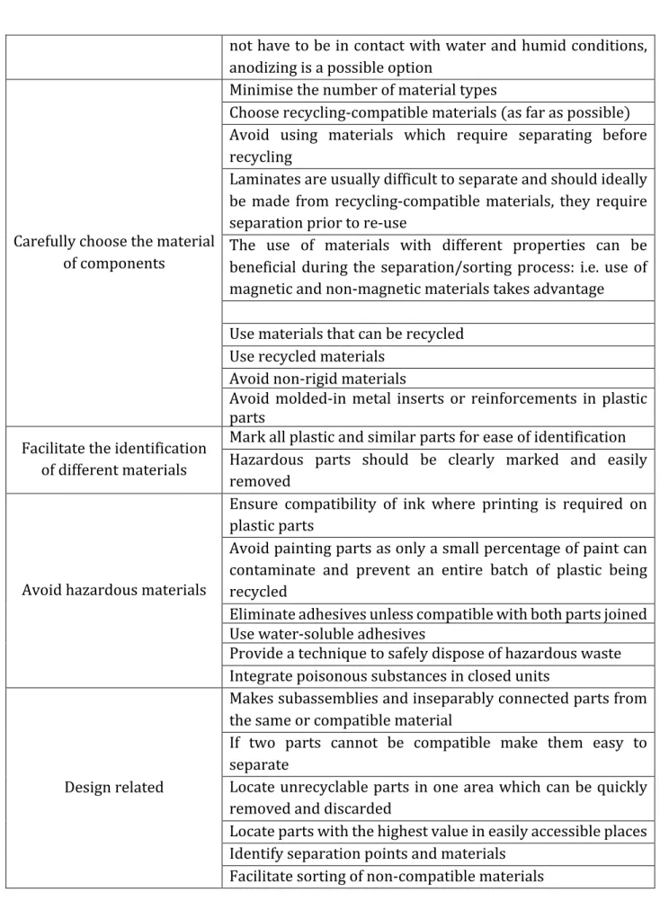
22 not have to be in contact with water and humid conditions, anodizing is a possible option Carefully choose the material of components Minimise the number of material types Choose recycling-compatible materials (as far as possible) Avoid using materials which require separating before recycling
Laminates are usually difficult to separate and should ideally be made from recycling-compatible materials, they require separation prior to re-use
The use of materials with different properties can be beneficial during the separation/sorting process: i.e. use of magnetic and non-magnetic materials takes advantage Use materials that can be recycled Use recycled materials Avoid non-rigid materials
Avoid molded-in metal inserts or reinforcements in plastic parts
Facilitate the identification of different materials
Mark all plastic and similar parts for ease of identification Hazardous parts should be clearly marked and easily removed
Avoid hazardous materials
Ensure compatibility of ink where printing is required on plastic parts
Avoid painting parts as only a small percentage of paint can contaminate and prevent an entire batch of plastic being recycled Eliminate adhesives unless compatible with both parts joined Use water-soluble adhesives Provide a technique to safely dispose of hazardous waste Integrate poisonous substances in closed units Design related Makes subassemblies and inseparably connected parts from the same or compatible material
If two parts cannot be compatible make them easy to separate Locate unrecyclable parts in one area which can be quickly removed and discarded Locate parts with the highest value in easily accessible places Identify separation points and materials Facilitate sorting of non-compatible materials
Table 3. Set of Guidelines for Disassembly: Design, Fasteners and Materials related.
23
2.4 Robotic Disassembly
In contrast to the state of the art of flexible assembly automation, disassembly for recycling today is mainly a manual and, to some extent, mechanized process [23]. Disassembly of products for recycling today poses a lot of problems technically, legally and financially. A fully automated process for disassembly is known only for particular problems where no flexibility of the automated system is required such as unscrewing bottles for refill, recycling of steel-barrels and the structured disassembly of some electronic and electrical equipment, e.g. computer monitors, PCBs [27].
Usually it has been a manual performance executed by human operators since the number uncertainties related to the quality and quantity of the products returned was too high to face an automatization, having the technology only partially developed [38]. In order to implement automation of disassembly for most technological products the fundamental requirement is a higher degree of flexibility compared to assembly-automation, due to the following reasons: • The time frame of use of the majority of products is usually longer than introduction-cycles of new products and it is typically between ten to fifteen years. Hence, a variety of generations of products has to be considered in the disassembly plant. • The condition of the products that have to be disassembled varies broadly due to ageing, corrosion, damage, etc.
The main reasons for introducing robotic disassembly are economic. Consumer goods, especially electronics ones, threatens to overwhelm existing, costly, inefficient and time-consuming manual disassembly operations.
Several have been the attempts to automate the disassembly process [29][30]. The main objective was the one to replace high-cost labour-intensive disassembly activities with low-cost automated option. The uncertainties associated with products at the End Of their Lives (EOL products) have been an issue for human operators and represent even more a complexity for automation. That is due to the level of decision making, operating skills and high level of perception required to disassemble the product. In case of human operators, a skilful one should implement the disassembly of previously unseen models of products and make decisions based on their knowledge and perception on product’s conditions. In case of robotic automation, the capabilities are even less in all aspects: flexibility and robustness in dealing with these uncertainties are limited.
The physical uncertainties in EOL products results in potential defects, damage, wear and tear, etc. to some parts or components, or to the entire product. It is very probable that he quality of the product in this condition might be quite different from the original one. In addition, the nature of EOL products in a product group can vary according to the model and brand. Thus, an enormous database must be developed to obtain correct information about a wide range of product models. Lastly, as a result of the two previously problems, disassembly sequence might be complex to define since detailed knowledge of a particular product is needed [28].
As Fig. 7 illustrates, robotic semi-destructive disassembly represents the intersection of robotic, non-destructive and destructive disassembly. Semi-destructive disassembly represents an intersection between destructive and non-destructive disassembly since some components are destroyed while theirs are dismantled. Alternate and equally valid
24
interpretations of semi-destructive disassembly define it as a subgroup of destructive disassembly which intentionally executes an incomplete destructive disassembly. By both definitions, semi-destructive disassembly is a process that partially destroys an item with the final aim to separate its materials and components into single ones.
Figure 7. Venn’s Diagram on different approach to disassembly [28].
The decision process required during the disassembly is similar to those a human operator should make. A prior knowledge and information during the process must be gained. Sensor systems cannot always provide all information needed, thus we can rely only on the perceivable ones. As a consequence, there is a certain level of uncertainty and the following variations should be taken into account:
• variations in the structure of the products;
• variations in the disassembly process planning (DPP); and • variations in the quality and quantity of the components.
During the automated process, the perception of the condition of the product is obtained mainly by the sensing modules, namely the vision system. Such information should generate the disassemble at an operational level (i.e. generation of a path planning and path trajectory, planning of sequence). For example, [31] develop an automatic decision-making scheme based on a fuzzy reasoning Petri net. [32] developed an automatic control of the operations based on available resources. [33] use a predictive-model with a disassembly Petri net to generate the optimal Disassembly Sequence Plan (DSP) based on the physical condition of the product. However, even though the existing research is flexible for physical unexpected conditions, information regarding the product’s structure needs to be supplied a priori. At the moment, there are no researches that focus on variations in the product’s structure.
That is why that starting to improve the design of products in a disassembly perspective would facilitate the automation of the process and minimize the uncertainty and complexity
25
2.5 References
[1] MacArthur, Ellen. ‘Towards the Circular Economy.’ Journal of Industrial Ecology (2013). [2] Lancaster, Mike. Principles of sustainable and green chemistry. Blackwell, Abingdon, UK, 2002. [3] Dario, P., Rucci, M., Guadagnini, C., & Laschi, C. (1993, November). An experimental robot system for investigating disassembly problems. In Advanced Robotics, 1993. Can Robots Contribute to Preventing Environmental Deterioration? Proceedings, 1993 IEEE/Tsukuba International Workshop on(pp. 37-42). IEEE.[4] Andersen, M. S. (2007). An introductory note on the environmental economics of the Circular Economy. Sustainability Science, 2(1), 133-140.
[5] Jacobsen, N. B. (2006). Industrial symbiosis in Kalundborg, Denmark: a quantitative
assessment of economic and environmental aspects. Journal of industrial ecology, 10(1-2), 239-255.
[6] Andersen, O. (1997). Industrial ecology and some implications for rural SMEs. Business
Strategy and the Environment, 6(3), 146-152.
[7] Andersen, B. (1999). Industrial benchmarking for competitive advantage. Human Systems
Management, 18(3, 4), 287-296.
[8] Moving toward a Circular Economy, Markus Zils,
http://www.mckinsey.com/business- functions/sustainability-and-resource-productivity/our-insights/moving-toward-a-circular-economy accessed online February 2017.
[9] Zhou, Kui, et al. A study on circular economy implementation in China. Working papers
2014-312, Department of Research, Ipag Business School, 2014.
[10] Pollard, Duncan, et al. "Living planet report 2010: Biodiversity, biocapacity and
development." WWF International, Institute of Zoology, Global Footprint Network (2010). [11] Meadows, Donella, Jorgen Randers, and Dennis Meadows. Limits to growth: The 30-year update. Chelsea Green Publishing, 2004. [12] Stott, Peter A., et al. "Detection and attribution of climate change: a regional perspective." Wiley Interdisciplinary Reviews: Climate Change 1.2 (2010): 192-211. [13] Nasr, N., and E. Varel. "Lifecycle analysis and costing in an environmentally conscious manufacturing environment." APICS remanufacturing symposium proceedings. 1996. [14] Boothroyd, G., and L. Alting. "Design for assembly and disassembly." CIRP Annals-Manufacturing Technology 41.2 (1992): 625-636.
[15] Ghandi, Somayé, and Ellips Masehian. "Review and taxonomies of assembly and
disassembly path planning problems and approaches." Computer-Aided Design 67 (2015): 58-86.
[16] Schneider, W. "Automating Small-Lot Electronic Production." IRE Transactions on
Production Techniques 3.1 (1958): 50-59.
[17] Pettinaro, Giovanni C. "Behaviour-based peg-in-hole." Robotica 17.02 (1999): 189-201. [18] Abdullah, Mustafa W., et al. An Approach for Peg-in-Hole Assembling using Intuitive
Search Algorithm based on Human Behaviour and Carried by Sensors Guided Industrial Robot." IFAC-PapersOnLine 48.3 (2015): 1476-1481.
[19] Whitney, Daniel E. "Quasi-static assembly of compliantly supported rigid parts." Journal
26
[20] Chhatpar, Siddharth R., and Michael S. Branicky. "Search strategies for peg-in-hole
assemblies with position uncertainty." Intelligent Robots and Systems, 2001. Proceedings. 2001 IEEE/RSJ International Conference on. Vol. 3. IEEE, 2001. [21] Desai, Anoop, and Anil Mital. "Evaluation of disassemblability to enable Design for Disassembly in mass production." International Journal of Industrial Ergonomics 32.4 (2003): 265-281. [22] Mok, H. S., H. J. Kim, and K. S. Moon. "Disassemblability of mechanical parts in automobile for recycling." Computers & Industrial Engineering 33.3-4 (1997): 621-624. [23] Warnecke, H-J., M. Schwelzer, and M. Kahmeyer. "Flexible disassembly with industrial robots." Proceedings of the International Symposium on Industrial Robots. Vol. 23. INTERNATIONAL FEDERATION OF ROBOTICS, & ROBOTIC INDUSTRIES, 1992.
[24] Dowie, Tracy, and Matthew Simon. "Guidelines for designing for disassembly and recycling." Manchester Metropolitan University. Manchester (1994).
[25] Harjula, T., et al. "Design for Disassembly and the environment." CIRP Annals-Manufacturing Technology 45.1 (1996): 109-114.
[26] Reap, John, and Bert Bras. "Design for Disassembly and the value of robotic semi-destructive disassembly." Proceedings of the ASME design engineering technical conference, Montreal, Que., Canada. New York: American Society of Mechanical Engineers. 2002.
[27] Knoth, Reinhard, et al. "Automated disassembly of electr (on) ic equipment." Electronics and the Environment, 2002 IEEE International Symposium on. IEEE, 2002.
[28] Vongbunyong, Supachai, Sami Kara, and Maurice Pagnucco. "Basic behaviour control of the vision-based cognitive robotic disassembly automation." Assembly Automation 33.1 (2013): 38-56.
[29] Buker, U., et al. "An active object recognition system for disassembly tasks." Emerging Technologies and Factory Automation, 1999. Proceedings. ETFA'99. 1999 7th IEEE International Conference on. Vol. 1. IEEE, 1999.
[30] Torres, Fernando, Santiago Puente, and Carolina Díaz. "Automatic cooperative disassembly robotic system: Task planner to distribute tasks among robots." Control Engineering Practice 17.1 (2009): 112-121.
[31] Gao, Meimei, MengChu Zhou, and Ying Tang. "Intelligent decision making in disassembly process based on fuzzy reasoning Petri nets." IEEE Transactions on Systems, Man, and Cybernetics, Part B (Cybernetics) 34.5 (2004): 2029-2034.
[32] Kim, H-J., S. Chiotellis, and G. Seliger. "Dynamic process planning control of hybrid disassembly systems." The International Journal of Advanced Manufacturing Technology 40.9 (2009): 1016-1023.
[33] Salomonski, Nizan, and Eyal Zussman. "On-line predictive model for disassembly process planning adaptation." Robotics and Computer-Integrated Manufacturing 15.3 (1999): 211-220
27
3. Dependability
Our aim is to fully describe what defines a robotic platform dependable (meaning, “to be trusted”). All parameters and how these can be quantified are reported. Dependability studies help to assess the feasibility when implementing new robotic processes, such the ones of robotic Disassembly. The background information reported in this Chapter support the analysis of Chapter 5, paragraph 5.3.5, in comparison with the robotic case study reported in Chapter 6, paragraph 6.3.2. In fact, human performances when implementing the task of unscrew during disassembly are analysed and benchmarked with the robotic unscrew.3.1 Intro on dependability
Dependability is defined as the system property that integrates the following attributes, reliability, availability, safety, security, maintainability [1]. In 1985, Laprie defined dependability “as the trustworthiness of a computer system such that reliance can justifiably be placed on the service it delivers” [2] meaning that it identifies the ability to deliver service that can justifiably be trusted [3]. Since early days, providers and users have been working on the delivery of correct computing and communication services. In the first electronic computers developed in the late 1940’s and mid-50’s, rather unreliable components were used, therefore practical techniques were born in order to improve their reliability [1].The way a user – intended as human, physical system interacting with other systems - perceive the behaviour of a system represents the service itself. The function of a system is what the system is planned to do, and is described by the functional specification. Another way to define dependability is “the ability of a system to avoid failures that are more frequent or more severe, and outage durations that are longer, than is acceptable to the user(s)” [1]. This definition complements the initial one since provides a criterion for adjudicating whether the delivered service can be trusted or not. A systematic exposition of the concepts of dependability consists of three parts. The dependability tree has been now adapted and changed compared to the first developed by Laprie, as shown in Fig. 1[1]: 1. the threats to 2. the attributes of, and 3. the means by which dependability is attained
28
Figure 1. The dependability tree: (top) Laprie’s definition [2]; (bottom) the version adapted in this study.
29 Threats to a system’s dependability consist of failures, errors and faults, while means have to be adopted for pursuing dependable systems and consist of “fault avoidance” actions, seen as the combination of fault prevention and fault removal, and “fault acceptance” actions, through fault forecasting and fault tolerance processes[4]. Dependability’s attributes, such as reliability, availability, safety, security, survivability, maintainability, are conceived as the system properties [3].
Dependability is a term used for a general description of system performance but not a quality which could be expressed by a single quantitative measure.
A system is taken as dependable if it satisfies all requirements of the customers with regard to various dependability performances and indices. The dependability deals with failures, repairs, preventive maintenance as well as with costs associated with investment and service interruptions or mission failures. Therefore, it is a very important attribute of system quality.
The level of dependability possessed by a system should be considered in a relative, probabilistic sense, and not in an absolute, deterministic sense. Since faults are impossible to completely avoid, systems are never totally available, reliable, safe, or secure.
3.2 Attributes of dependability
Dependability is a concept obtained by the integration of basic attributes, the following: • reliability: continuity of correct service, • availability: readiness for correct service, • safety: absence of catastrophic consequences on the user and the environment, • confidentiality: absence of unauthorized disclosure of information, • integrity: absence of improper system state alterations; • maintainability: ability to undertake repairs and modifications. Different attributes might gain more importance based on the applications of a specific system. As an example, availability is always required, although to a varying degree, whereas reliability, safety, confidentiality may or may not be required at all. Variations in highlighting different attributes of dependability consequentially affect the way to apply the techniques (fault prevention, tolerance, removal and forecasting) in order to make the resulting system dependable.The dependability requirement of a specific system is obtained by the performances of its attributes based on the acceptable level of frequency and severity of the failure modes and its acceptable outage durations.
Other dependability attributes have arisen, but these are either combinations or specializations of the six basics ones. One of these is “security”, which is the concurrent existence of a) availability for authorized users only, b) confidentiality, and c) integrity with ‘improper’ taken as meaning ‘unauthorized’. It is also possible to characterize a system reaction to faults through “robustness”, which is dependability with respect to erroneous inputs.
What is clear is that dependability, with its property of trustworthiness, adds a third dimension to system quality that is based on cost and performance, becoming fundamental in the development of new technology, see Fig. 2:
30
Figure 2. System Quality in terms of dependability towards cost and performance [3].
3.2.1 Reliability
Reliability can either be intended as a characteristic for an item or as a performance measure. If we intend it as a characteristic for an item, its definition is “the ability to perform under given conditions for a given time interval”, while as a performance measure it is “the probability of a system to be able to perform as required under given conditions for the time interval”. Reliability can be identified in various different ways. No one can be considered the best in all circumstances, but some can be more or less than others under certain conditions. The most common method of defying reliability is to quote it as a mean value using a term such as “Mean Time Between Failures”, MTBF, for a repairable item or “Mean Time To Failure”, MTTF, for a non-repairable item.Reliability can also be intended as a probability of success without specifying an operating time. For example, in case of one shot device (i.e. a missile), the requirement would be specified as a probability of success without a time qualification as the objective is the item to be used successfully against its predefined usage profile [5].
The most used measure of reliability is defined by the mean time to failure (MTTF). MTTF is the expected value of the reliability:
MTTF = |{𝑅 𝑡 𝑑𝑡
The hazard rate h(t) is the instantaneous rate of failure at a given time. The reliability function and the hazard rate are related as 𝑅 𝑡 = exp − •ℎ 𝑥 𝑑𝑥 | In reliability models is described how hazard rate changes over time. In general, for the majority of electronic and mechanical devices, if we plot the hazard rate as a function of time, the
31
resulting curve resembles a bathtub curve, see Fig. 3. The shape has three distinct regions: at the left side, the hazard rate decreases with time as corresponds to the period during which items fail mainly because of defects in materials or construction; in the middle section, the constant hazard rate is approximately constant and random failures dominate since is the period of service life or useful life; at the right side, the hazard rate increases with time since components usually have reached the end of their useful lives and begin to deteriorate. When the bathtub model (see Fig. 3) is applied to robot modules, we take into count that there will be an initial period of testing which allows burn-in failures to be dealt with before items are brought into service.
Figure 3. Bathtub curve of reliability [5].
In addition, we assume also that manufacturers will specify service life of components so that modules will be removed from service before the “wear out failures” phase begin to dominate. For such reasons, only during service life phase it necessary to know the hazard rate of a robot module. This hazard rate is modeled as a constant and thus it can be defined by a single value. It is also important to know when the hazard rate is valid thus a second value is needed: the service life length. The reliability of an item can therefore be modeled with just two parameters—the (constant) hazard rate and the service life length [5][7].
3.2.2 Availability
Availability represents the statement if a system is operational at a point in time / fraction of time, and describes system behaviour in presence of error treatment mechanism. Availability can be thought of as the probability that an item or system is up at any random instant in time (the probability that it is down is 1 minus the availability) [5]. It can be viewed as the probability that the system (or one component) is in a state able to perform its required function under specified conditions at a specified instant in time. Availability is also determined by a system’s reliability, as well as its recovery time once a failure does arise.Availability is one of most important factors since, when a failure occurs, it becomes fundamental to know how quickly the system can be recovered.
32 recover a system once a failure happens. This may comprise the time it takes to diagnose the problem and to get a repair specialist onsite, and also the time it takes to actually repair the system. Another parameter is “Mean Time Between Failures”, MTBF, and similar to MTTF, is represented in units of hours. While MTTR impacts availability, it has not any influence on reliability. The longer the MTTR, the worse off a system is since if it takes longer to recover a system from a failure, the system is going to have a lower availability. The formula below shows the availability in terms of MTBF and MTTR. From that, it is possible to understand how they influence the overall availability of a system: as the MTBF rises, availability decrease. As well in case the MTTR goes up.
Availability = ƒ„…†
ƒ„…†‡ƒ„„ˆ
In order for the equation above to be valid, we have to assume that most electronic systems don’t have moving parts thus should be generally accepted that electronic systems or components exhibit constant failure rates during the useful operating life. In Fig. 3, the "normal operating period" or “useful life period" represents the stage at which a product is in use in the field. At this stage, product quality has levelled off to a constant failure rate with respect to time. The sources of failures at this stage could include defects impossible to detect, poorly designed safety factors, random stress higher than expected, human factors, and natural failures. What can prevent a rapid decay curve presents in the "wear out period" are long burn-in periods, proper maintenance, and proactive replacement of worn parts. The discussion above provides the background to comprehend differences of reliability and availability, allowing for the proper interpretation of MTBF [6]. If MTBF or MTTF is very large compared to MTTR (repair or replace), then we will obtain a high level of availability. Likewise, if mean time to repair or replace is low, then availability will be high.
3.2.3 Maintainability
Maintainability as well can either be defined as a characteristic for an item or as a performance measure. As a a characteristic for an item, it can be defined as the ability to be retained in, or restored to a state to perform as required, under given conditions of use. As a performance measure, it represents the probability that a given maintenance action, performed under stated conditions and using specified procedures and resources, can be completed within the time interval (t1, t2) given that the action started at t = 0. In general, the purposes are the one of setting meaningful requirements, thus maintainability is taken to be a performance measure. The time to bring an item back to a fully operational condition once an incident occurred will be dependent on two factors: the physical time it takes to diagnose and undertake the repair and the time to obtain the required spares, tools and a maintainer skilled of undertaking the
33
work. As a consequence, we will have two different times, the Active Repair Time (ART), diagnose and repair time, and the Active Repair Time (ART) that includes logistic delays. The most common method of obtain maintainability is through the use of a mean time, either as a Mean Active Repair Time (MART) or a MTTR. If maintainability requirements are set at early stages of the life cycle of an item, they might be used to influence the design in terms of its maintainability before major decisions have been made [5].
Maintainability is also related to availability. The shorter maintenance time, the higher is availability of the system [8]. As reliability decreases (i.e., MTTF becomes smaller), better maintainability (i.e., shorter MTTR) is required to achieve the same level of availability. In case reliability increases is then not important that maintainability to achieve the same availability. Thus, trade-offs can be made between reliability and the willingness to achieve the same level of availability. As a consequence, two disciplines must work hand-in-hand to achieve the objectives.
3.2.4 Safety
Safety is primarily linked to detection of potential danger, be it due to an endogenous or an exogenous hazard. When a potential danger is identified, a safeguard procedure (i.e. a shutdown) can be initiated. Such a safeguard procedure can be viewed as a specific form of forward recovery.
Usually reliability/availability and safety are simultaneously required. By knowing that the safest system is the one that never does anything, a compromise has to be made. By trying to ensure continued operation (thus having reliability/availability), the risk is that a current or future hazard might be mishandled and a catastrophic failure might happen. In other hands, by shutting down the system every time there is the suspect of a danger (safety), we decrease the continuity of service delivery [9].
Safety aims at lowering to zero the probability of a catastrophic failure. Mechanisms for ensuring safety focus on both the detection of errors that might violate safety constraints and positioning the system in a safe state [4].
Safety and dependability are fundamental aspects that lead to a successful introduction of robots into human environments. For example, robots for physical assistance to humans should in general improve the quality of life by reducing fatigue and stress while increasing human capabilities in terms of force, speed, and precision [1]. Only dependable robot systems can be accepted for supporting “human-in-the-loop” conditions and human-robot teams. However, while safety issues are usually considered for robot servants, there is a lack of safety standards for HRI.
Since the focus is on cognitive interaction, robot companions have typically a simpler mechanical design.
![Figure 1. The dependability tree: (top) Laprie’s definition [2]; (bottom) the version adapted in this study](https://thumb-eu.123doks.com/thumbv2/123dokorg/2927923.18844/29.892.98.808.117.1086/figure-dependability-tree-laprie-definition-version-adapted-study.webp)
![Figure 9. Extended dexterous manipulation taxonomy. With respect to the original classification presented in [4], sub-categories of “not within hand” and “within hand” are added in both the “prehensile, no motion” and “non-prehensile, no motion” section](https://thumb-eu.123doks.com/thumbv2/123dokorg/2927923.18844/68.892.88.807.735.1079/extended-dexterous-manipulation-classification-presented-categories-prehensile-prehensile.webp)