DISI - Via Sommarive, 14 - 38123 POVO, Trento - Italy http://disi.unitn.it
Client announcement
and Fast roaming
in a Layer-2 mesh network
Antonio Quartulli and Renato Lo Cigno
October 2011
Technical Report # DISI-11-472 Version 1.0
Extended abstract1
Research in Wireless Mesh Networking has been really active in the last years, with the birth of various ideas and the protocols that implement them. Nevertheless all the cur-rently most deployed protocols have a lot of room for improvement and there are still open challenges that are meant to bring the performance to higher levels.
Wireless Mesh Networks are involved in several studies also because of their applica-tions which can be particularly useful in all those situaapplica-tions where wired infrastructures are not feasible.
Common implementations rely on Layer-3 addressing and routing, but doing Mesh networking on Layer-2 address space is probably the best way for building a protocol needed to handle this kind of networks, since this task is not strictly related to the network (IP) layer. In particular, efficient client managing is not possible in case of a mesh routing protocol implemented on Layer-3 and this is probably one of the most important tasks of the routing protocol (after establishing routes, of course).
This technical report focuses on the client announcement and the roaming problems that a protocol, embedded between Layer-2 and Layer-3, has to face. In particular, it focuses on B.A.T.M.A.N.-Advanced and defines new mechanisms that are meant to improve the protocol performance in client management and roaming.
The current client announcement mechanism suffers from several problems, in partic-ular from a high protocol overhead. The new strategy described in this technical report is meant to reduce such overhead and to increase the robustness of the whole announcement strategy.
Up to now B.A.T.M.A.N.-Advanced hasn’t ever provided a real mechanism to han-dle the roaming procedure, so this is the first one accounting this issue in the protocol. Performance are increased dramatically thus making it possible to measure real benefits in the user communications. This is probably the most prominent result obtained in this work which actually brings new possibilities for further improvements and for designing new mechanisms.
The B.A.T.M.A.N.-Advanced protocol is actually transparent to the network layer by design, so the base idea behind the new roaming mechanism is to keep such transparency providing an on-time re-routing of the batman encapsulated data packets to the new
1
This Report has been submitted in fulfillment of the “Research Project in Systems and Networks” by Antonio Quartulli and promoted to DISI TR after revision by Prof. Renato Lo Cigno
destination. In this way it is possible to avoid affecting upper layers keeping them unaware of roaming, thus keeping all the connections active.
The new mechanisms have been tested in the worst case roaming scenario for B.A.T.M.A.N.-Advanced. Such scenario consists in a topology made up by a chain of nodes of length N (the longer the chain, worse the performance) on top of which a client served by the first node and one served by the last one are communicating. In case of any client movement (e.g. roaming to an adjacent node) the time needed by the new routing information to be spread among the network, and consequently make the connection work again, is pro-portional to the number of links that separate the two involved nodes. The experimental results, that are reported at the end of the technical report, show that even in this par-ticular scenario the performance improvement given by the new mechanism is significant. The tests have been performed in an emulated environment where virtual machines, which acted as nodes, were created using QEMU-KVM. Therefore it has been possible to use the real B.A.T.M.A.N.-Advanced code instead of a possible error-prone implementa-tion for any of the known network simulators (NS-2, NS-3, OMNET++, etc..).
Keywords: B.A.T.M.A.N.-Advanced; mesh networking; wireless; QEMU; roaming; client announcement.
Contents
1 Introduction 1
1.1 Wireless Mesh Networks . . . 1
1.1.1 Network architecture . . . 1
1.1.2 Routing in Wireless Mesh Networks . . . 2
1.1.3 Related work . . . 3
1.1.4 The research project . . . 4
1.2 B.A.T.M.A.N.-Advanced: Better Approach to Mobile hoc Networking - Ad-vanced . . . 5 1.2.1 Background . . . 5 1.2.2 The protocol . . . 5 1.2.3 Improvements overview . . . 8 1.2.4 Meshing on layer 2 . . . 8 2 Announcing Clients 11 2.1 The current strategy . . . 11
2.2 A new mechanism . . . 11
2.2.1 General idea . . . 11
2.2.2 Recognise local translation-table changes with a single value . . . 12
2.2.3 Update the global translation-table . . . 13
2.2.4 Deal with node reboot and consistency . . . 16
3 Speeding up the Roaming procedure 19 3.1 The current strategy . . . 19
3.2 A new mechanism . . . 20
3.2.1 Handling the roaming phase . . . 20
3.2.2 Forwarding data packets . . . 22
4 Experiments 25 4.1 Emulation . . . 26
A Compute the Path TQ 29 A.1 (Local) Transmit Quality . . . 29
A.2 Asymmetric links . . . 29
A.3 Hop count . . . 29
B Packet formats 31 B.1 OGM . . . 31
B.2 Translation Table Query (Request or Response) . . . 31
B.3 Roaming Advertisement . . . 32
B.4 Unicast Packet . . . 33
C Source code reference 35 C.1 Files . . . 35
Chapter 1
Introduction
1.1
Wireless Mesh Networks
A Wireless Mesh Network [1] (WMN) is a communication network made up of several nodes connected in a mesh topology by means of wireless links [2]. In the general case the topology is not a full mesh so that the communications between nodes must exploit multi-hop paths to form a connected network.
The main wireless mesh network target is to replace the expensive wired backbone that interconnects network access points with a wireless backbone, thus reducing the costs while increasing the fault tolerance.
Wireless mesh networks can potentially have a lot of applications, for example they can be used to reduce the digital divide for those regions in which the wired connectivity is not well deployed or totally absent.
1.1.1 Network architecture
In a wireless mesh network it is possible to categorise nodes in two different classes: mesh routers and mesh clients.
Mesh routers are in charge of creating the network backbone and are usually fixed, built with homogeneous hardware and possibly equipped with multiple radios.
A mesh router can also be connected to a larger network (like Internet) and can provide access to the rest of the mesh network participants. In this case the router is also is called mesh gateway1.
Mesh clients are end-user devices like workstations, PDAs, mobile phones or laptops. They can establish a connection to a router using any common networking interface avail-able, like ethernet or wifi. The most common approach is to use wifi connections, because routers are usually access points deployed in a large area. This is another reason why 1In the 802.11s [3] draft Mesh Client, Mesh Router and Mesh Gateway are respectively named Mesh
Station, Mesh Point and Mesh Portal. A Mesh Point providing connectivity to Mesh Stations is called Mesh Access Point
mesh routers are usually equipped with more than one radio: at least one device can be used in Infrastructured mode to let clients connect. Another common (and cheaper) solution consists in using single radio devices but enabling multiple virtual interfaces; the performance in this case is significantly poorer.
It is also possible to categorise clients in two classes: mesh aware and mesh agnostic clients.
If the clients are mesh aware they actively participate to the backbone connectivity and can also act as mesh router too. In this case the difference between clients and routers only resides in the deployment, but they are the same from a logical point of view. Mesh agnostic clients, instead, are normal nodes that get connected to the mesh through one of the routers without having any idea of how the networks works and how packets are routed.
The latter is the most common approach because in this case clients don’t need to know the network mechanisms and they only have to establish a connection with one of the mesh routers.
The approach studied in this report regards a mesh network made up of routers and mesh-agnostic clients. As said this is one of the most common approach and the one on which the research project want to focus on.
1.1.2 Routing in Wireless Mesh Networks
As described in the previous section, a wireless mesh network is a multi-hop network where nodes are deployed over a certain area. Hence, to make it possible that all nodes reach one another, even when not in range, a routing protocol is needed.
A routing protocol permits to every host participating in the protocol session to dis-cover other nodes in the network and to build a routing table that will contain all the information needed to route packets toward one of the known destinations.
In the literature it is possible to find several routing algorithms widely used on wired network like RIP, BGP and OSPF but none of them is suitable for a wireless network. The problem resides in the fact that all these protocols assume wired links with almost no packet losses. As it is possible to understand these characteristics doesn’t fit very well a wireless mesh networks, where links are subject to degradation and quality fluctuation in time. For this reason a good routing algorithm has to take into consideration different factors that depends on the local links to compute the best route.
All the routing algorithms proposed for MANET [5] and Wireless Sensor Network (WSN) [6] could probably work in a WMN, but none of them takes the peculiarities of such network into account. In particular, routing algorithms proposed for MANET focus more on power consumption than throughput, so they are not very efficient in a WMN.
In the last decade, some algorithms have been proposed specifically for WMN. The cur-rent routing protocols can be divided in two big family: reactive and proactive. Reactive protocols, like AODV [7], build paths on demand reducing the overhead traffic generated
by the routing protocol. In contrast proactive routing protocols, like OLSR [8], Babel or B.A.T.M.A.N. [21], permanently maintain the optimal links toward all the destinations.
There are advantages and drawback for both the solutions, in particular reactive rout-ing protocols show slow convergence while proactive ones usually have low scalability.
The chosen routing protocol is fundamental for the resulting performance of the mesh network. In particular, each protocol adopt a different mechanism for computing the link and the path quality, so for this reason using one or another algorithm, in the same scenario, could lead to completely different results.
1.1.3 Related work
Several works have been published on the Wireless Mesh Networking topics, in particular regarding either the physical or the network layer. This report focuses on the latter where the routing protocol resides. For a general overview and comparison of the most deployed routing protocols see [10]. However a common problem that all the protocols must face is the client announcement, which is the mechanism that advertises mesh agnostic clients over the network and makes it possible to serve them. Each protocol uses its own strategy which can vary depending on the implementation choices. The strategy used to imple-ment the client announceimple-ment mechanism is strictly related to another important topic: the roaming process. The latter relies on the former mechanism and exploits its func-tionalities in order to make the handover efficient. Actually there is the IEEE802.11r [11] standard which is in charge of specifying all the requirements and mechanisms to provide fast handover process in wireless LANS on the MAC layer. Moreover [12], [13] and [14] describe other techniques to apply on the Data-Link layer to decrease the latency of the handover process.
On the other hand, Wireless Mesh Networks depend on the routing protocols which sits on top of the MAC layer. Thus to exploit the lower layer improvements, the routing protocol needs to provide roaming functionalities as well.
Actually, the literature provides several solutions studied within the ATM/WATM frame-work whose ideas can be apply to Wireless LANs and Mesh Netframe-works. In particular, some interesting articles have been identified: [15] lists several issues that can affect the roaming process in a wireless ATM network. [16] and [17] describe some techniques used to implement the roaming mechanism in these networks.
[18] makes a short summary of common mechanisms used to face seamless handover. In the survey it is possible to find [19] and [20] which describe the re-routing technique, that is widely used in several protocols.
Finally [9] presents a roaming mechanism implemented on top of OLSR that introduces several ideas about the client context switching in modern Mesh Networks with multiple gateways.
1.1.4 The research project
This research project will focus on the B.A.T.M.A.N.-Advanced routing protocol, in par-ticular it will concern two major features: the client announcement and the roaming mechanism.
In the current implementation of this protocol, the former suffers from several problems and needs to be improved, while the latter is totally absent.
The idea behind this research project is to find an efficient strategy to announce clients that first removes the current limits and then gives the bases on top of which it is possible to implement an efficient roaming procedure.
The next chapters will describe the new client announcement strategy and the fast roaming procedure that have been figured out and implemented during this project. Each chapter will also describe what is the state of the current implementation, the disadvan-tages and the design problems.
1.2
B.A.T.M.A.N.-Advanced:
Better Approach to Mobile Ad-hoc Net-working - Advanced1.2.1 Background
B.A.T.M.A.N.-Advanced [21] (B.A.T.M.A.N. from now on) is a proactive mesh routing protocol and it can be (mostly) classified as Distance Vector. In a mesh network using this protocol, every node is aware of every others and in particular it knows which is the best next-hop toward them. In this way there is no need to calculate the full route thus, providing a very fast end efficient implementation.
To achieve this result, every node periodically broadcast an Originator Message (OGM), which announce the presence of the node. The interval at which OGMs are sent is called Originator Interval (it is fixed to 1 second in the current implementation).
Some of the OGM fields are the address of the sender (originator address), the TTL, the sequence number (SN) and the transmission quality (TQ).
The originator address is the unique identifier of a node in the network. The sequence number is a counter and it is used for several purposes. The path transmission quality (TQ) represents the quality of the path traversed by the originator message and it is the B.A.T.M.A.N. routing metric.
The following sections will explain how the TQ value is computed among the path and how the fourth version of the B.A.T.M.A.N. protocol works (the last up to now).
At the end of this chapter some interesting scenarios and how B.A.T.M.A.N. handles them will be described.
1.2.2 The protocol
As introduced above, the entire protocol is based on flooding the network with a particular message called OGM and using the information contained in these messages to create and maintain the routing table.
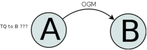
It is widely known that wireless links, unlike wired ones, are not always symmetric in term of quality and packet loss. For an intermediate node, the most important attribute of a local link toward a given neighbour is the Transmit Quality, because when choosing a link the protocol wants to evaluate the capability of sending data, not receiving it. Unfortunately the transmit quality can not be directly measured (Figure 1.1) and for this reason two additional parameters are introduced: the Receive Quality (RQ) and the Echo Quality (EQ).
RQ is computed as the fraction of OGMs received from a given node with respect to the number of expected ones. EQ is the fraction of locally generated OGM packets that a node receives back from a neighbour that is rebroadcasting them with respect to the number of the generated ones.
In order to infer the TQ towards a neighbour, every node has to first compute RQ and EQ.
Figure 1.1: A sends an OGM to B. A can’t directly determine the (Local) Transmit Quality towards B
(Local) Transmit Quality (TQ)
It is easy to understand that the Receive Quality approximates the probability of receiving a packet from a given node, while the Echo Quality approximates the product: EQ = T Q × RQ. Given these assumptions it is possible to calculate the TQ simply reverting the last formula: T Q = EQ
RQ
How to compute the Receive Quality (RQ)
As said above, RQ approximates the probability of receiving an Originator Message (Fig-ure 1.2) generated by a given neighbour. The operation of computing the RQ is done maintaining for each neighbour an OGM’s sequence numbers (SN) sliding window. In this structure the sequence numbers of the received OGMs generated by a given neighbour are marked. In particular, when receiving an OGM with SN value m the upper value of the sliding window is moved to m (and it is marked as received) while the lower one is set to m − W IN DOW SIZE. All the information regarding previous values are discarded.
The Receive Quality value is obtained dividing the number of OGM’s sequence numbers marked in the window by the window size.
Figure 1.2: Node A shifts B’s window and marks the OGM’s Sequence Number it received. It can compute the Receive Quality by counting marked SN
How to compute the Echo Quality (EQ)
The Echo Quality approximates the probability of receiving our own packets after they are rebroadcasted from a given neighbour (Figure 1.3). The EQ value is computed in a similar way as described for the receive quality: for each neighbour there is a sliding window of the echoed OGM packet sequence numbers and for each OGM generated by the node itself, that is received after a neighbour rebroadcasts it, the corresponding sequence
Figure 1.3: Node A shifts B’s echoed packet window and marks the OGM’s Sequence Number it received. It can compute the Echo Quality by counting marked SN
number in the window is marked. Moreover, each time a new own OGM is scheduled, all the windows is shifted by one.
The Echo Quality value is obtained dividing the number of OGM’s sequence numbers marked as received in the window by the window size.
The Transmit Quality approximates the probability of successfully forwarding a mes-sage to a neighbour.
(Path) Transmit Quality
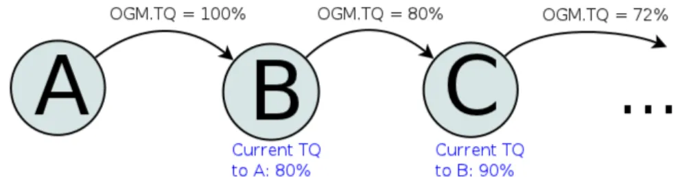
The Path Transmit Quality is the value associated to an entire path between two nodes and it is computed and spread using the OGM rebroadcast mechanism. In particular, an OGM, when generated by a node, will contain the maximum value for the TQ field (representing 100%); then, after being received and before being evaluated by the next node, the Path TQ value contained in the message is modified according to some rules that take into consideration link asymmetric, path length in number of hops and finally the local TQ towards the OGM sender (See appendix A for more details). Figure 1.4 shows how the (Local) Transmit Quality affects the propagated value. The resulting value is the Transmit Quality of the path from the rebroadcasting node to the OGM source and it is used as metric to evaluate the different routes the rebroadcasting node can have towards this source.
Figure 1.4: Transmit Quality propagation. Each node, before rebroadcasting an OGM, multiplies the carried TQ (OGM.TQ) by the (Local) TQ towards the previous sender of such message
The TQ value in the rebroadcasted OGM is replaced by the best Path TQ that the node has seen towards the originator. In this way the best path information is spread in the network along all the possible residual paths.
Eventually all the nodes will have a routing table consisting of an entry for each originator node containing the path transmit quality they computed and a list of potential next-hops where the best (the one that propagated the highest TQ) is used for routing.
1.2.3 Improvements overview
In the various B.A.T.M.A.N. releases some features have been added to counter problems and slightly increase the performance. The rest of this section will briefly present the most interesting ones.
OGM aggregation
The aggregation permits to reduce the overhead caused by forwarding many small OGM packets.
Whenever there is more than one OGM to forward, an aggregated packet is created and all the messages received before a certain amount of time (maximum aggregation time) are attached to it until the size of the whole packet is less than the maximum aggregation size. When the time expires the aggregated packet is sent reducing the number of transmissions.
Gateway mode
In a mesh network, for its nature, is is possible to have several exit points which connect the entire network to a another one (e.g. The Internet). Those exit points are called gateway. Usually more than one exit point is used to provide redundancy for load balancing and fault tolerance.
The B.A.T.M.A.N. protocol provides a feature that permits gateways to advertise themselves on the routing protocol level. In this way, nodes that accepted to elaborate such information will choose the best one (in terms of TQ) as its mesh default gateway. This information is used to forward all DHCP [25] request, which the node receives from the clients it is serving, to the the default gateway only, avoiding to contact all the other gateways in the mesh network.
Moreover, it is possible to observe how this mechanism improves the DHCP broadcast reliability as collateral effect, since the DHCP request is sent using a unicast communica-tions. Clearly the DHCP server must be co-located with a client served by the gateway node (or with the node itself).
1.2.4 Meshing on layer 2
From a couple of years B.A.T.M.A.N. has moved from a layer 3 implementation to a layer 2 one (2.5 would be more correct as it resides between the data-link and the network layer running in kernel and not on NICOS but using MAC addresses) without changing the routing algorithm.
B.A.T.M.A.N. now represents a new level in the network stack, with its own encapsu-lation header and its own services. It became totally transparent to the IP protocol since it now works like an extended LAN with standard ethernet socket exposed to the IP layer.
It is easy to understand that this new implementation leads to several implications: • B.A.T.M.A.N. does not use IP addresses to work;
• B.A.T.M.A.N. can be configured to use any interface which is capable to send Eth-ernet frames thanks to the Linux Kernel abstraction (hence not only EthEth-ernet inter-faces);
• the MAC address of the physical devices is used as unique identifier;
• at the IP layer, every packet sending operation is seen as a one-hop communication; • due to the B.A.T.M.A.N. encapsulation every MPDU size is increased by 24 bytes (the B.A.T.M.A.N. header size). For this reason it is strongly suggested to increase the MTU of the involved physical interfaces from 1500 to 1527, being careful that it is only runs PHY/MAC layers that allow MTUs larger than 1500 bytes.
Actually the B.A.T.M.A.N. fragmentation mechanism is already implemented, so in case of packets too big to encapsulate in one frame, the payload is split in several parts that are successively sent one by one.
However this scenario would lead to performance degradation and it is strongly suggested to avoid it and to rely on a higher MTU value for the involved physical interfaces.
Another advantage of working on layer 2 is the possibility of using multiple interfaces and logically join different network segments into one broadcast domain. The next two section illustrate two implemented techniques to exploit the presence of multiple interfaces.
Interface alternating
To improve the performance, B.A.T.M.A.N. takes into account the possibility of exploiting all the network interfaces used to connect to the mesh network. In case of multiple-radio devices this becomes extremely useful due to the shared nature of the wireless medium.
The alternate interface strategy modifies the routing using this information. In partic-ular, a packet will never be forwarded on the same interface on which the node received it, but possibly trough a different one if the Transmit Quality is such to avoid performance degradations.
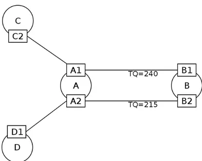
As shown in Figure 1.5, nodes A and B are connected through two different interfaces. In this case, every packet sent to node B, that have to pass through A, will be forwarded on the interface not used for receiving it.
Figure 1.5: Nodes with multiple interfaces. Interface alternating at A: packets directed to B received through A1 are forwarded using A2 and viceversa
Interface bonding
An alternative to the interface alternating strategy is the interface bonding. It consists in sending packets to a neighbour using all the available interfaces in a round robin fashion. Data packets are alternatively sent through the two available interfaces from one node its neighbour exploiting the sending parallelism.
The main drawback of this strategy is the maximal throughput being limited by the interface with the worst bandwidth. Moreover the quality of the worst link will affect the entire transmission.
Currently the interface bonding is disabled by default while the interface alternating strategy is used. However the bonding topic is still an open work and there is a lot of room for improvements.
Handling broadcast data packets with user payload
It is easy to understand that when dealing with wireless links the packet loss is never negligible. For this reason unicast packet are transmitted using a MAC based ARQ mech-anism. Unfortunately this is not feasible for broadcast packets. Therefore the probability of losing a packet of these increases with the number of links it is going to traverse.
For this reason, in order to increase the success probability of transmissions, each broadcast packet containing a user payload (packets coming from the userspace, not gen-erated by B.A.T.M.A.N.) is forwarded multiple times (3 in the current implementation). However, a node receiving duplicated broadcast packets will deliver and forward the first one only while it will ignore all the others.
Chapter 2
Announcing Clients
2.1
The current strategy
In the current implementation, the B.A.T.M.A.N. protocol uses a quick, but not optimised, strategy to announce the clients served by a mesh node. In particular, each node will attach to its own OGMs an announcement buffer containing all the client MAC addresses it is currently serving. In this way all the nodes that will receive these OGMs are able to store this buffer in a translation table that will successively be used for look up operations. This “spread and store” procedure is executed for each OGM, which means that in case of fixed clients (for instance, clients that are always connected to the same mesh node) the protocol overhead is quite high even if not definitely needed. Moreover it is possible to observe overhead either on the network side, because the OGMs travelling over the network are always bigger than the simple case (no clients), either on the node side where useless computations are always needed (nodes need to compare the new announcement buffer with the old one to look for changes each time they receive a new OGM).
Going deeper into this mechanism it is possible to observe another problem: the an-nouncement buffer size. Since the client addresses are attached to one OGM, it is not possible to push as many addresses as wanted, because the OGM packet size is limited by the ethernet frame maximum size (the interface MTU which is usually 1500Bytes). This obviously leads to limit the number of clients a node can announce and consequently serve.
2.2
A new mechanism
2.2.1 General idea
To solve the problems that have been figured out in section 2.1, it has been decided to totally redesign the announcement mechanism.
First of all, the network overhead problem has been considered: the new mechanism has to avoid wasting air-bytes and should transmit data only if really needed. Consequently, the node overhead will decrease as there will be less information to elaborate.
To achieve this result, in the new mechanism every node has its own Translation Table Version Number (TTVN from now on) which represents the version of the node local translation-table (the table containing all the MAC addresses of currently served clients). Each time something changes in the table (a client is added or removed) the TTVN is increased to reflect the new version of the local translation-table. As it is possible to understand, this number represents the local translation-table state of a node and can be easily used by the rest of the network to understand whether this node has something new to announce or not with respect to the current state.
To make all the network aware of the local table state, each node will send its current TTVN value within the OGMs, as a new field. In this way nodes receiving the OGM can compare such value with the one already known for that originator (the OGM source) and decide whether they need a table update or not. These TTVN spreading and table update mechanism will be fully explained in the following sections.
The first observation is that this strategy drastically reduces the protocol overhead limiting the size of the data to be sent. Useless information are not sent anymore avoiding wasting of bytes.
2.2.2 Recognise local translation-table changes with a single value
To make the rest of the network recognise that a specific node has modified its local translation-table, the OGM packet format has been modified by adding a new field: the Translation Table Version Number (TTVN). This field will be filled with the current sender’s TTVN while generating the packet.
Each node, when creating an entry for a new originator node, assumes that its TTVN is equal to 0 and that its local translation-table is totally empty.
On the other side, each node at boot time initialises its own TTVN to 0 and its own local table as empty. From that moment on, each time the node recognises at least one local change (a new client comes up or an old client times out) during an OGM interval the node will increase its own TTVN by 1. With this assumptions it is possible to state that a TTVN incremented by 1 represents a set of local changes happened in the originator local translation-table during the last OGM interval.
Moreover, in order to exploit this changes grouping, each OGM carries the last set of changes that triggered the last TTVN increment (if the number of changes is small enough to fit in one OGM). To reach a good tread-off between overhead and reliability, it has been decided to resend the last set of changes 2 times more if nothing new happened in the meantime.
In this way, receiving all (or most of) the OGMs is enough to guarantee the global translation-table consistency on all the nodes. As it is possible to understand nodes are keeping track of changes in a proactive fashion.
2.2.3 Update the global translation-table
The global translation-table is a data structure in which a node stores all the client ad-dresses announced by the other originators with a reference to the mesh node that is serving them.
This table is basically used as a normal routing table where the client address is used as search key and the originator address is the result. In this way, every time a node wants to send a packet to a generic client, it has to search the global translation-table for the client address and retrieve the originator address which will be used as real destination for the batman layer (Section 1.2.4).
Using the TTVN as described in section 2.2.2 it is simple to understand whether a node has to ask for a translation-table update: it is enough to compare the previous TTVN received from a certain mesh node and the new TTVN value carried by its last OGM. In case of mismatch the receiver node has to ask the originator for a table update.
For this purpose two new packet types have been introduced: the TransTable Request and the TransTable Response. With these two messages a node is able to request a table update and to retrieve the missing set of changes in order to restore the consistency of its own global translation-table.
In the first step, the concept of “update” coincided with the complete table, which means that, in case of TTVN mismatch, the node asking for the update would receive the complete originator local translation-table and will overwrite all the old entries pointing to such node.
With this first idea we are already avoiding to send useless data in the OGMs (Section 2.1), since we are sending local translation-tables on-demand only.
In the second step, the concept of “update” has been optimised so that if a node missed a fixed number of change-sets it could directly ask for that information reducing the amount of data that need to be transmitted in the TransTable Response.
To account this feature, a tracking system has to be provided, so that each node can keep an history of its local changes to scroll back in case of TransTable Request.
It is easy to understand that the functions needed by this mechanism would lead to higher overhead on the node computation side and to a probable-bug-prone implementation. For this reason a simpler mechanism has been proposed: instead of keeping a history of all the local changes, a node has to keep only the last change-set it sent within the last OGM. In this way, the overhead of creating such history is zero (the change-set has to be already prepared to be sent within the OGM) and no single-change tracking mechanism is needed.
Receiving an OGM
After discussing how the update mechanism works, in this subsection some of the algorithm details are going to be explained.
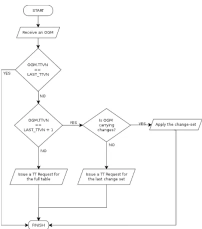
Figure 2.1: Flow chart illustrating the TTVN evaluation on receipt of a OGM. LAST TTVN is the last seen TTVN for the OGM’s source node
In particular, when receiving an OGM there are several options that can apply (Fig-ure 2.1):
1. the TTVN in the OGM (OGM.TTVN) is equal to the last received from that origi-nator (OGM.SRC.TTVN)): no changes happened since last global translation-table update.
2. the OGM.TTVN is equal to OGM.SRC.TTVN + 1: something happened in the last OGM interval
• the OGM carries the change-set: apply the changes to the global translation-table
• otherwise: issue a TransTable Request for the last change-set only
3. the OGM.TTVN is greater than OGM.SRC.TTVN + 1: the receiving node missed at least one OGM carrying changes and needs to issue a TransTable Request for the complete table
Announcement and frame size
As mentioned in section 2.1, one of the problems of the current B.A.T.M.A.N. client announcement implementation is the maximum number of client that a node can announce within a single OGM. The limit is given by the number of MAC addresses that can fit in one ethernet frame (usually 1500Bytes).
In this new mechanism, since nodes are now announcing table changes instead of MAC addresses, a node can potentially serve an infinite number of clients communicating their addresses OGM by OGM.
Nevertheless there are two issues to face:
1. a change-set can be bigger than the maximum amount of data an OGM can carry 2. a complete table could not fit into one single TransTable Response
In the first case the proposed solution is to do not send any change within the OGM, so that, respecting the rules described in section 2.2.3, a node will issue a TransTable Request to ask for the missing data. In this way the first problem has been traced to the second. Regarding the second case, the basic idea was to provide a fragmentation mechanism in order to split the unique big TransTable Response in several packets with size less than the MTU. This idea has successively been retired because the B.A.T.M.A.N. community claimed it wants to implement a general fragmentation framework that works with any kind of B.A.T.M.A.N. packet, regardless of its type. At that point also the second problem will be solved. Currently, in case of such problem, the number of MAC address carried by the TransTable Response is still limited by the MTU.
Avoid unicast storming
The main purpose of this new announcement strategy is to limit the protocol overhead given by useless information being sent to announce clients. With the mechanism described in the previous sections, the protocol is going to save a lot of air-bytes due to the reduced OGM size on the average case.
Another point that have to be taken into consideration, while implementing the new strategy, is the overhead introduced by the TransTable Request/Response mechanism. In order to keep it low, the protocol should try to reduce the number of on-fly messages as much as possible.
However it is possible to note that the new strategy has already given the protocol enough information to implement a forward-breaking function and obtain the mentioned result. In particular, a node has to block a request for which it can already answer (because it has the requested data) or has to block a request for data for which it has already issued its own one. In the latter case the node has to keep track of this new request and has to reply as soon as it gets its own response.
• Requests inspection • Requests queueing
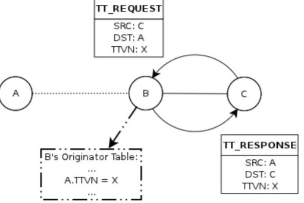
TransTable Request inspection on the path : A generic node on the TransTable Request path has to inspect the message and check whether it already has the change-set the message is trying to retrieve and has to directly response with a TransTable Response without forwarding the request packet (Figure 2.2). In case of request of a too old change-set or full table, the intermediate node can directly answer itself with the entire table of the real destination node.
Figure 2.2: Request inspection and forward-breaking. C sent a TT REQUEST to A; the first hop (B) inspects the message and decides to immediatly reply with a TT RESPONSE without forwarding the request
It could also be possible that the intermediate node doesn’t have the last change-set for several reasons (e.g. memory problems or missing change-set on the last OGM due to size). Even in this case, the node will directly reply with the full table.
TransTable Request queueing on the path : A generic node on the TransTable Request path, that has already sent another request message for the same change-set, has to enqueue the received message and has to directly reply with a TransTable Response as soon as it receive its own.
This second sub-procedure is only a proposal. It has not been really implemented in the new strategy as its improvement is just marginal, but it can be considered as part of future work.
2.2.4 Deal with node reboot and consistency
As described in section 2.2.2, the Translation Table Version Number is the value respon-sible for triggering an update request. Receiving an higher value means that something changed in the node’s table and an update is needed. At this point it is easy to understand that if a node reboots, and the sequence restarts from zero, the nodes in the network won’t be able to understand what is happening anymore.
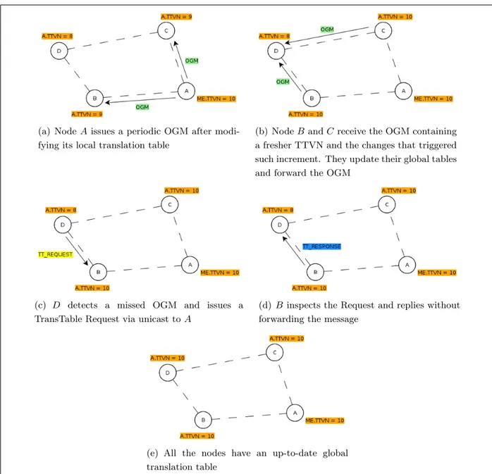
(a) Node A issues a periodic OGM after modi-fying its local translation table
(b) Node B and C receive the OGM containing a fresher TTVN and the changes that triggered such increment. They update their global tables and forward the OGM
(c) D detects a missed OGM and issues a TransTable Request via unicast to A
(d) B inspects the Request and replies without forwarding the message
(e) All the nodes have an up-to-date global translation table
Figure 2.3: An example scenario that summarise the new announcing mechanism.
A node could receive a lower or equal TTVN which makes it to ignore the changes. This behaviour will obviously lead to an inconsistent global translation-table and it is definitely unacceptable.
To solve this problem a new value has been introduced: the Translation Table CRC (TT CRC). Algorithm 1 shows the pseudo code that explain how this value is calculated given an originator.
The computation is executed each time a node modifies its global table for a certain originator node. The same value is also computed for the own local translation-table and it is spread within the OGM together with the TTVN.
Algorithm 1 : Compute the Translation Table CRC
1: orig node = {node for which the computation is needed}
2: tt crc = 0
3: for all gte ∈ global trans table do
4: if gte.orig node == orig node then
5: tmp = crc16(gte.client address)
6: tt crc = tt crc XOR tmp
7: end if
8: end for
9: return tt crc
modified to take it into account. A node that receives an OGM has to compare the TT CRC value carried by the message with the previously computed TT CRC for that originator node. In case of negative match a Translation Table Request for a full table is issued.
It is also possible to notice that the TT CRC is guaranteeing at the same time that node global translation-tables are always consistent with respect to the various local ones. In case of consistency breaking due to a malicious or corrupted node, this new value will help originators to recognise the problem and recover a sane table.
Chapter 3
Speeding up the Roaming
procedure
The target of this section is to explain how B.A.T.M.A.N. currently handle the roam-ing procedure and how the new announcroam-ing mechanism explained in chapter 2 helps in improving it.
The idea is to reduce as much as possible the time needed for an already established connection to be recovered after that a client moved from a node to another, reducing the number of dropped packets and guaranteeing an acceptable continuity to real-time services.
3.1
The current strategy
In the current implementation, in case of roaming the B.A.T.M.A.N. protocol simply attaches the new client address to the next OGM sent out by the mesh node currently serving it, so that every node in the network can learn the new route to the client as soon as they receives that message. This means that the protocol doesn’t really handle the roaming event itself, but it simply relies on the normal announcing mechanism (Section 2.1).
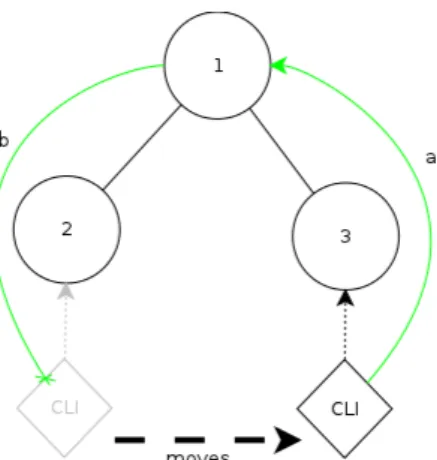
As illustrated in Figure 3.1, a client moving from one node to another has always the possibility to correctly send packets the destination, because its location is well known and every node has a route towards it.
This is not obviously true for the other direction: the client has moved and the other endpoint has to wait for the new information to learn where the client is now located. This update, due to the nature of the protocol, will take some time (even seconds, de-pending on the topology - see Figure 3.2) since the OGMs are sent in broadcast and could be easily lost along the path. Moreover, in the worst case, the new client information will need to wait an entire OGM interval before starting to be spread.
Figure 3.1: Roaming in the old implementation. The moving Client CLI can immediately send packets through the correct route (a), while node 1 uses the wrong route (b) until it will receive the new OGM from 3
imagine a scenario in which the clients are using VoIP or video streaming applications (or any other software with strict latency constraints) this will obviously lead to a service degradation.
Figure 3.2: One of the worst topology case. CLI moves from node 6 to node 7: in order to make CLI recover its connection to node 1 the client has to wait for 7’s OGM to reach 1 first. The probability of losing the OGM increases with the number of links to traverse
3.2
A new mechanism
3.2.1 Handling the roaming phase
Currently in B.A.T.M.A.N. there is not a real roaming handling procedure. With the new client announcing mechanism (Section 2.2) this aspect is going to be improved too.
The term roaming refers to the event of a client that get disconnected from a mesh node and get connected to another one, usually while moving around, without losing network connectivity.
Keeping in mind how the announcing mechanism works, it is easy to understand that all the nodes sending data to the moving client will continue to send their packets to the old mesh node which was serving it, until they receive an updating OGM from the new
one.
This operation could take several seconds (depending on the topology - Figure 3.2 shows one of the worst case) and could need various retransmissions (OGMs could be lost and the changes would have to be recovered via the request/response mechanism).
This amount of time is definitely unacceptable and the mechanism has to be improved to reduce as much as possible the number of data packets that are going to be lost during this route assessment.
The mechanism that will be introduced consists in explicitly advertise a roaming event so that the involved nodes can apply the adequate and essential modification to their routing tables in order to make already established connections continue to work even if sub-optimally.
In particular this mechanism will consists in using a new packet type, the Roaming Advertisement. A message of this type will be sent whenever a node detect a roaming event. To recognise this situation, a node detecting a new local client, will first check whether it already knows a route toward this client. In case of positive match the new node understands that the client moved and it entered in a roaming phase. In this situation, keeping in mind the main target (reduce the amount data packets lost during roaming), the new node needs to do something in order to correct the other nodes route. Since it doesn’t know which were all the hosts that were communicating with the client, it is not possible to recover all the connections one by one, moreover there could be new hosts that want to start new connections in this moment. So the idea is to exploit the only guaranteed common point among all the deprecated routes: the old node that was serving the roaming client.
The Roaming Advertisement packet is sent in unicast to the old mesh node. In this way it will be able to correct its translation-table pointing the client entry to the new node.
In the following sections how to exploit this new information while forwarding traffic in the B.A.T.M.A.N. mesh network will be explained.
Moreover another detail has to be focused: the old node, when receiving the Roaming Advertisement, will track this change as a removal event and will spread it in the next OGM, but, in this case, a flag is set on the change: the TT CHANGE ROAM. At this point, a node that receives the OGM will increase the source node’s TTVN but will not delete the client address from its routing table: it will only mark the entry with the TT GLOBAL ROAM flag. The entry flag will be reset later, on receipt of the OGM from the new node owning the client.
This startegy helps for two different purposes:
• the entry ensure that the node is always able to route packets towards the client • the flag is used to avoid to include this entry in the CRC calculation
During a roaming phase involving two mesh nodes, say A and B, and a client, say C, that moved from A to B a Roaming Advertisement message is sent from B to A. Upon receiving the message the latter will delete the client from its local table and will add it to its global one. From now on, the local crc computation of A will not take the roaming client C into consideration. At the same time, all the other nodes in the network will still keep a route to C using A as destination, until an OGM from B is received.
This means that all the nodes have to avoid to take C into consideration while computing A’s CRC, otherwise they will obtain a wrong value.
To achive this result A has to specify in some way that the address in this change (a delete in this case) belongs to a ”roaming client”. Here comes the roaming flag. Adding this flag to the change structure will make receiving nodes able to understand whether this is a roaming client or not.
3.2.2 Forwarding data packets
A node that wants to send a new data packet seaches the translation table for the client to obtain the originator address to use as destination.
In the current implementation once the packet has been forged and sent out, no one of the forwarding nodes modifies it until the destination is reached. If the receiving client has moved in the meanwhile the packet will be lost as soon as it reaches the old node.
Instead, with the new announcing mechanism (Section 2.2) each node has a TTVN value for each originator which represents a time notions about the information it owns. This value is used to evaluate, step by step, whether a forwarding node has a newer information regarding the destination. If so it can possibly look up its translation table and check whether the client to reach is no more located at the same node. In that case the node has to route it to the correct direction.
To make this strategy work, a mesh node generating a unicast packet has to include the TTVN of the destination node within the B.A.T.M.A.N. header. In this way, each node that receives the packet can inspect it and act as described aboved. In case of re-routing the node has to care about substituting the destination address and TTVN with the new data.
In Figure 3.3 it is possible to observe an example of roaming client which shows the new roaming handling procedure.
(a) Client Cli receives data from EXT through C and A
(b) Client Cli moves to-ward B and switches its WiFi connection from A to it. Data starts being lost by A
(c) As soon as B detects the new Host, a unicast Roaming Advertisement is sent to the node that served Cli to inform it of the roaming phase
(d) A immediately starts forwarding the data it receives to the new Cli’s manager node
(e) B sends a new OGM and the rest of the network get in-formed of the change
(f) All the nodes now know where Cli is lo-cated and the data is routed through a new path
Chapter 4
Experiments
To test the new implementation and to measure the performance gain given by the new client announcement and roaming mechanism, some tests have been planned.
The test which are going to be reported have been performed in an emulated envi-ronment. Some real deployment tests have also been performed but no significant results have been collected due to the limited number of available routers. However these tests were useful to validate the implementation and spot possible bugs.
The next sections will first describe the testbed and then will show the obtained results.
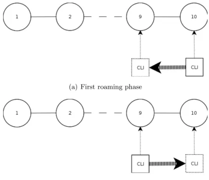
(a) First roaming phase
(b) Second roaming phase
Figure 4.1: The test scenario is divided in two phases: the client CLI firstly roams from node 10 to node 9 (a) and then it roams backward from node 9 to node 10 (b)
4.1
Emulation
The tools that have been used to perform the tests are: • QEMU-KVM: to emulate the mesh nodes
• patched vde switch: to emulate the wireless medium
• wirefilter: to emulate the wireless link with its properties (bandwidth, packet loss, delay)
The first test has been performed using 10 virtual machines interconnected through a chain topology, (one of the worst situation for the old B.A.T.M.A.N. client announcement implementation) without any link degradation: delay and packet loss were set to 0. This test is pretty useful as initial study to understand the theoretical improvement given by the new implementation.
The test consists in a client connected to a generic node in the mesh network doing a flooding ping to the node number 1 while moving around. In particular, to keep the test as simple as possible, the client roams only between two nodes. Therefore, as shown in figure 4.1, the test consists of two different roaming phases:
• Client moving from node 10 to node 9 • Client moving from node 9 to node 10
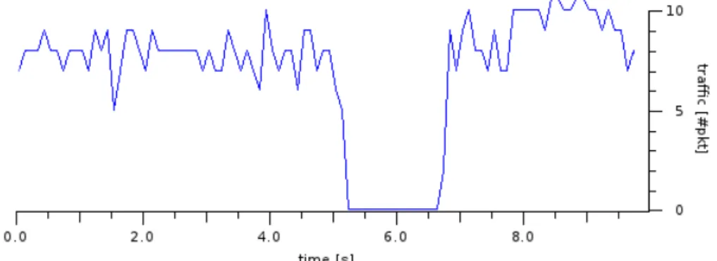
Figure 4.2: Client moves from node 10 to node 9: Old implementation
The ICMP flows going in both directions have been dumped to a file, but, as explained in section 2.1, packets going from the client to node 1 will always reach the destination. Therefore, only the interesting graphs with the ECHO REPLY packets flowing from node 1 to the client will be shown.
In Figure 4.2 and 4.4 it is possible to see the data flow during a roaming phase using the current B.A.T.M.A.N. implementation. As shown, data is getting lost for a certain amount of time (about 1.5 seconds), in particular, for a period needed by the data sender (node 1) to get informed of the new client location. In figure 4.3 and 4.5 instead it is possible to see as no gap is present at all during the client roaming phase.
Figure 4.3: Client moves from node 10 to node 9: New implementation
Figure 4.4: Client moves back from node 9 to node 10: Old implementation
The result of this test is not as worse as expected because links have no packet loss, so the first OGM immediately reaches all the nodes and permit them to update the translation-table. In a real deployment, with the same topology, a worse result is expected: the probability of an OGM of traversing 10 links without getting lost is pretty small and so the expected delay for recovering the connections would be larger.
Figure 4.5: Client moves back from node 9 to node 10: New implementation
The second test can be considered identical to the previous one from a logical point of view, but it is not the same from the implementation prospective. Therefore this second experiment is useful to understand whether the algorithm has been correctly implemented or not.
In figure 4.4 and 4.5 it is possible to see the same result as shown before: using the old implementation it is possible to observe a gap in which data is lost, while using the new implementation the result is definitely better. Observing the graph it is not even possible to identify the period in which the client roamed, since no gap is present at all.
Appendix A
Compute the Path TQ
The Path Transmit Quality (Path Quality from now on) is affected by several parameters while being forwarded within the OGM. In the next sections the factors that affect this value are going to be explained in detail.
A.1
(Local) Transmit Quality
Upon an OGM reaches a new hop, the Path Quality is decreased based on the Transmit Quality of the last traversed link. In particular:
P athT Q = P athT Q ∗ LocalT Q
A.2
Asymmetric links
While propagating the Path Quality, B.A.T.M.A.N. takes into account asymmetric links too. In this way, a particular link could be used in one direction but not in the other, exploiting its asymmetry. But asymmetric links are still a problem also if used in the right direction due to ACKs losing. Therefore the Path Quality value has to be decreased if the traversed link has a poor Receive Quality. This result is achieved penalising the Path Quality value on the asymmetry of the link using an inverse cubic function:
P athT Q = P athT Q ∗ (1 − (1 − RQ)3)
A.3
Hop count
Another aspect that must be taken into account while modifying the Path Quality value is the hop-count. B.A.T.M.A.N. decreases the Path Quality by a fixed factor each time an OGM is rebroadcasted; in this way longer paths are penalised.
P athT Q = P athT Q ∗ (1 − T Q HOP P EN ALT Y ) In the current implementation TQ HOP PENALTY is 0.03.
Appendix B
Packet formats
In this section all the packet types that have been modified or added during this research project will be explained. For those types already present in B.A.T.M.A.N.-Advanced the new field only will be described (in bold in the format diagram).
B.1
OGM
1. . . .
2. TT VER NUM: the translation table version number of the sender 3. TT CRC: the local translation table CRC
4. TT NUM CHANGES: the number of tt change entries that are appended to the OGM
5. . . .
B.2
Translation Table Query (Request or Response)
1. PACKET TYPE: batman packet type 2. VERSION: batman compatibility version
4. TTL: Time To Live
5. FLAGS: a combination of the following flags: TT REQUEST/TT RESPONSE and TT FULL TABLE
6. SRC ADDRESS: the address of the source node of the message 7. TTVN:
• if TT REQUEST: it is the TT VERSION NUM that triggered the request, • if TT RESPONSE: it is the TT VERSION NUM related to the data being
sent. 8. TT DATA:
• if TT REQUEST: the crc value that triggered the request,
• if TT RESPONSE: the total number of entry that are appended to this message.
B.3
Roaming Advertisement
1. PACKET TYPE: batman packet type 2. VERSION: batman compatibility version
3. DST ADDRESS: the old node address which served the client 4. TTL: Time To Live
5. SRC ADDRESS: the new node address which is serving the client 6. CLIENT ADDR: the roaming client address
B.4
Unicast Packet
1. . . .2. TTVN: it represents the TT VERSION NUM known for the destination node. this field is set by the source node and can be possibly modified by each node along the path (as described in section 3.2.2).
Appendix C
Source code reference
The code that has been produced during this research project is available on the Open-Mesh website (www.open-mesh.org). A separated git repository was dedicated for the purpose and contained the project patches until they were merged into the master branch. The master branch is the main B.A.T.M.A.N.-Advanced development git branch in which all the patches are merged when ready to be tested so that people can find possible bugs. After this testing period, patches will be merged into the next branch ready for the next release and, since B.A.T.M.A.N.-Advanced is a linux kernel module, later they will be pushed to the linux kernel tree.
The code is currently on the third step of this path: it has been merged into the master branch and it has been pulled into the net-next-2.6 kernel branch. It is still under testing and evaluation by the B.A.T.M.A.N.-Advanced community. Later on the patchset will finally be merged in the linux kernel tree resulting in being shipped with version 3.1.
C.1
Files
The new client announcement mechanism touched most of the files belonging to the B.A.T.M.A.N.-Advanced module, but the main changes can be found in:
• translation-table.{c/h} • routing.{c/h}
• send.c • packet.h
translation-table.c, as the name suggests, is the file containing all the functions that manage the local and the global translation-tables. As it is possible to guess this is the file with the highest number of changes.
In routing.c it is possible to find all the functions that manage the forwarding proce-dures of the TT QUERY and ROAMING ADVERTISEMENT packets.
In send.c it is possible to find the functions needed to manage OMG buffers and appended data. Indeed this file contains all the procedures needed to append changes to the OGMs.
packet.h instead simply contains all the B.A.T.M.A.N.-Advanced packet definitions, therefore in this file it is possible to find the definitions of the structures representing the TT QUERY and the ROAMING ADVERTISEMENT packets.
Bibliography
[1] Akyildiz I.F., Xudong Wang, “A survey on wireless mesh networks”, Communications Magazine, vol.43, no.9, pp. S23-S30, Sept. 2005, IEEE
[2] IEEE 802.11 Standard Working Group, Draft Standard for Information Technology -Telecommunications and Information Exchange Between Systems - LAN/MAN Spe-cific requirements Part 11: Wireless LAN Medium Access Control (MAC) and Physical Layer (PHY) Specifications, IEEE P802.11-REVma/D9.0, January 2007
[3] IEEE 802.11s Task Group, Draft Amendment to Standard for Information Technology - Telecommunications and Information Exchange Between Systems - LAN/MAN Spe-cific Requirements - Part 11: Wireless Medium Access Control (MAC) and physical layer (PHY) specifications: Amendment: ESS Mesh Networking, IEEE P802.11s/D1.0, November 2006
[4] N. Nandiraju et al., “Wireless Mesh Networks: Current Challenges and Future Di-rections of Web-in-the-sky”, Wireless Communication, vol. 14, no. 4, pp. 79-89, Aug. 2007, IEEE
[5] I. Chlamtac, M. Conti, J. Liu, “Mobile ad hoc networking: imperatives and challenges”, Ad Hoc Networks, vol. 1, no. 1, pp. 13-64, July 2003, Elsevier
[6] I. F. Akyildiz, W. Su, Y. Sankarasubramaniam, E. Cayirci, “Wireless sensor networks: a survey”, Computer Networks, vol. 38, no. 4, pp. 393-422, March 2002, Elsevier [7] C. Perkins, E. Belding-Royer, S. Das, Ad hoc On-Demand Distance Vector (AODV)
Routing, RFC 3561, 2003, www.ietf.org/rfc/rfc3561.txt
[8] T. Clausen, P. Jacquet, Optimized Link State Routing Protocol (OLSR), RFC 3626, 2003, www.ietf.org/rfc/rfc3626.txt
[9] Costanzi G., Lo Cigno R., Ghittino A., Annese, S., “Route Stabilization in Infras-tructured Wireless Mesh Networks: an OLSRD Based Solution, Wireless on Demand Network Systems and Services”, Fifth Annual Conference on In Wireless on Demand Network Systems and Services, pp. 109-115, Garmisch-Partenkirchen, Germany, Jan. 2008
[10] Murray D., Dixon M., Koziniec T., “An experimental comparison of routing proto-cols in multi hop ad hoc networks”, Telecommunication Networks and Applications Conference (ATNAC), pp. 159-164, Auckland, New Zeland, Nov. 2010
[11] IEEE 802.11r Standard Working Group, Standard for Information Technology -Telecommunications and Information Exchange Between Systems - LAN/MAN Spe-cific requirements Part 11: Wireless LAN Medium Access Control (MAC) and Physical Layer (PHY) Specifications, Amendment 2: Fast Basic Service Set (BSS), July 2008 [12] Gondi V.K., Agoulmine N., “Low Latency Handover and Roaming Using Security
Context Transfer for Heterogeneous Wireless and Cellular Networks”, IEEE Services Computing Conference (APSCC), pp. 548-554, Hangzhou, China, Dec. 2010
[13] Chung-Ming Huang, Jian-Wei Li, “A Context Transfer Mechanism for IEEE 802.11r in the Centralized Wireless LAN Architecture”, Advaned Information Networking and Applications, 22nd International Conference on, pp. 257-263, Okinawa, Japan, March 2008
[14] Ha Duong, Arek Dadej, Steven Gordon, “Proactive context transfer and forced han-dover in IEEE 802.11 wireless LAN based access networks”, SIGMOBILE Mob. Com-put. Commun. Rev. 9, pp. 32-44, 2005
[15] Chrysostomou C., Pitsillides A., Pavlidou F., “A Survey of Wireless ATM Handover Issues”, Proc. of the International Symposium of 3G Infrastructure and Services -3GIS, 2001
[16] Akyol B.A., Cox D.C., “Rerouting for handoff in a wireless ATM network”, Personal Communications, vol. 3, pp. 26-33, no. 5, Oct. 1996, IEEE
[17] V¨ogel H., “Handover Switching in Mobile ATM Networks”, 1999
[18] V. Jacobson, “Congestion avoidance and control”, Symposium proceedings on Com-munications architectures and protocols, pp. 314-329, Stanford, California, United States, Aug. 1988
[19] M. Abolhasan, B. Hagelstein, and J. C.-P. Wang., “Real-world performance of current proactive multi-hop mesh protocols”, Proceedings of the 15th Asia-Pacific conference on Communications, pp. 42-45, Piscataway, NJ, USA, 2009
[20] Garroppo Rosario G., Giordano Stefano, Tavanti Luca, “Experimental evaluation of two open source solutions for wireless mesh routing at layer two”, 5th IEEE Interna-tional Symposium on Wireless Pervasive Computing (ISWPC), pp. 232-237, 5-7 May 2010
[21] Neumann A., Aichele C., Lindner M., Wunderlich S., “B.A.T.M.A.N.: Better Ap-proach To Mobile Ad-hoc Networking”, IEFT Draft, http://www.ietf.org/id/ draft-wunderlich-openmesh-manet-routing-00.txt (Expired Oct. 2008)
[22] D. Johnson, N. Ntlatlapa, and C. Aichele, “A simple pragmatic approach to mesh routing using BATMAN”, In IFIP International Symposium on Wireless Communi-cations and Information Technology in Developing Countries, Oct. 2008
[23] Nxumalo SL., Ntlatlapa N., Mudali, P., Adigun MO., “Performance Evaluation of Routing Metrics for Wireless Mesh Networks”, Southern Africa Telecommunication Networks and Applications Conference, pp 1-2, Swaziland, Aug. 2009
[24] Barolli L., Ikeda M., De Marco G., Durresi A., Xhafa F., “Performance Analysis of OLSR and BATMAN Protocols Considering Link Quality Parameter”, Advanced Information Networking and Applications, May 2009
[25] Droms R., Dynamic Host Configuration Protocol, RFC 2131, 1997, www.ietf.org/ rfc/rfc2131.txt