2018 Publication Year
2020-11-05T16:53:09Z Acceptance in OA@INAF
Antireflective coatings for the red camera of WEAVE spectrograph Title
Ortiz, R.; Carrasco, E.; Páez, G.; Reyes, J.; Hidalgo, Andrea; et al. Authors 10.1117/12.2313955 DOI http://hdl.handle.net/20.500.12386/28175 Handle PROCEEDINGS OF SPIE Series 10706 Number
PROCEEDINGS OF SPIE
SPIEDigitalLibrary.org/conference-proceedings-of-spie
Antireflective coatings for the red
camera of WEAVE spectrograph
Ortiz, R., Carrasco, E., Páez, G., Reyes, J., Hidalgo,
Andrea, et al.
R. Ortiz, E. Carrasco, G. Páez, J. Reyes, Andrea Hidalgo, Gavin Dalton, Scott
Trager, J. Alfonso L. Aguerri, Piercarlo Bonifacio, Antonella Vallenari, Don
Carlos Abrams, Kevin Middleton, "Antireflective coatings for the red camera of
WEAVE spectrograph," Proc. SPIE 10706, Advances in Optical and
ANTIREFLECTIVE COATINGS FOR THE RED CAMERA OF WEAVE
SPECTROGRAPH
R. Ortiz*
a, E. Carrasco
a, G. Páez
c, J. Reyes
a, Andrea Hidalgo
a,c, Gavin Dalton
c,d, Scott Trager
e, J.
Alfonso L. Aguerri
f, Piercarlo Bonifacio
g, Antonella Vallenari
h, Don Carlos Abrams
iand Kevin
Middleton
da
Instituto Nacional de Astrofísica, Óptica y Electrónica (Mexico)
bCentro de Investigaciones en Óptica (Mexico)
c
Department of Physics, University of Oxford (UK)
dSTFC Rutherford Appleton Laboratory (UK)
eKapteyn Institut, Rijksuniversiteit Groningen
(Netherlands)
f
Instituto de Astrofisica de Canarias (Spain)
gGEPI Observatoire de Paris, CNRS (France)
hOsservatorio Astronomico di Padova INAF (Italy)
i
Isaac Newton Group (Spain)
*[email protected]
ABSTRACT
In this work we present the coatings of the spectrograph red camera of WEAVE -the new
multi-object survey facility for the 4.2m William Herschel Telescope. The initial requirements of
WEAVE red camera lenses, with reflectances as low as 0.4% through the wavelength interval from
590 nm to 959 nm at angles of incidence of 18° +/- 17° represented a challenge for both design and
production. Based on initial requirements, several solutions to the same problem were achieved
and tested. The customized designs have been continuously improved through theoretical and
experimental approximations. From transmittance measurements at normal incidence we developed
a method to determine the reflectance at different angles of incidence. We show the designs and
coating transmittance obtained for the four glasses on test runs to guarantee that the designs were
achievable experimentally. Additionally, we present the reflectance obtained on the lenses of the
the first four lenses of WEAVE red camera.
Keywords: Antireflective coatings, spectrographs *[email protected] phone +52 222 266 3100
Advances in Optical and Mechanical Technologies for Telescopes and Instrumentation III, edited by Ramón Navarro, Roland Geyl, Proc. of SPIE Vol. 10706, 107065G · © 2018 SPIE
1. INTRODUCTION
WEAVE, acronyms of WHT Enhanced Area Velocity Explorer, is the new prime focus survey facility
for the 4.2m WHT. In Dalton et al. [1] [2] an extensive description of the whole instrument is presented. A fibre positioning system will distribute along the 2°diameter field of view almost ~1000 objects simultaneously, 20 small integral field units (IFUs) of 11" x 12" (1.3" spaxels) each or a large IFU that covers a 1.3' x 1.5' (2.6" spaxels) field of view. WEAVE spectrograph will offer spectral resolutions R~5800 in the wavelength interval of 366 - 959 nm and high resolution R~21000 in the ranges 404 - 465 nm, 473 - 545 nm and 595 - 685 nm. The spectrograph is formed by a collimator mirror, a dichroic that directs the light to a blue and a red camera. The dispersive elements are volume phase holographic gratings. The 8 lenses of the cameras are identical except for the coatings optimized for the 366 to 606 nm and 579 - 959 nm wavelength intervals respectively. The first lens is an aspheric while the other seven are spheric, all of them of large aperture, with diameters between 195mm to 320 mm, and high optical accuracy. The spectrograph optical design was carried out at RALSpace. The spectrograph mechanical structure is in progress at NOVA. The 660 mm diameter mirror and the 14 spherical lenses of both cameras are being manufactured at INAOE in Mexico. In Izazaga et al. [3][4] detailed descriptions of the collimator and camera lenses manufacturing process are described. Here we discuss the design of the antireflective (AR) coatings to fulfill the requirements. The coating designs and deposition processes were carried out in a collaborative squeme between INAOE and CIO. INAOE provided the designs and discuss the expected performance with the CIO team as the depositions were carried out at their lab.
1.1 AR coating specifications
The antireflective coating specification was: Reflectance Raverage < 0.3% (goal 0.2%), Rabsolute < 0.4% (0.3) for an angle
of incidence (AOI) between 0 and 35°, for a wavelength interval between 366 and 606 nm and 5790 to 9590 nm for the blue and red cameras respectively.
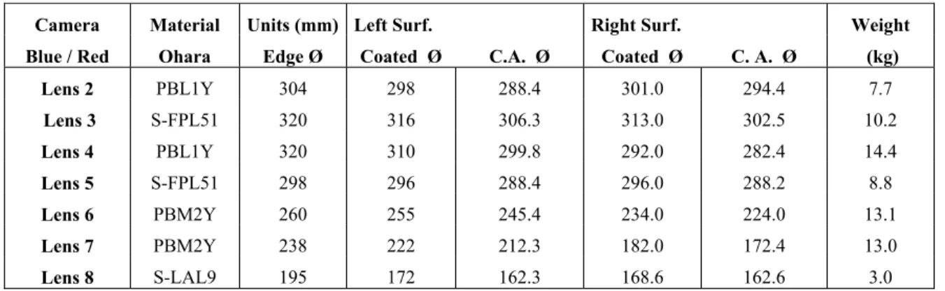
The optical quality requirements of the WEAVE spherical camera lenses are described in Izazaga et al. [2] and Hidalgo et al. [5]. In Table 1 the lenses main characteristics relevant to the coatings are presented. The largest diameter is 320 mm where the AR coatings must fulfill the requirements in Reflectance and adherence. For each camera, the coating designs where developed for four substrates: PBL1Y, S-FPL51, PBM2Y and SLAL-9.
Table 1. WEAVE camera lenses main characteristics.
Camera Material Units (mm) Left Surf. Right Surf. Weight
Blue / Red Ohara Edge Ø Coated Ø C.A. Ø Coated Ø C. A. Ø (kg)
Lens 2 PBL1Y 304 298 288.4 301.0 294.4 7.7 Lens 3 S-FPL51 320 316 306.3 313.0 302.5 10.2 Lens 4 PBL1Y 320 310 299.8 292.0 282.4 14.4 Lens 5 S-FPL51 298 296 288.4 296.0 288.2 8.8 Lens 6 PBM2Y 260 255 245.4 234.0 224.0 13.1 Lens 7 PBM2Y 238 222 212.3 182.0 172.4 13.0 Lens 8 S-LAL9 195 172 162.3 168.6 162.6 3.0
The main characteristics of these materials according to Ohara catalogue related to the coating design and deposition are shown in Table 2. The transmission properties of the coating depend mainly of the glass refractive index, the refractive index of the coating layers, the layers thickness and of the angle of incidence of the light into optical surface. The coatings are designed to produce that the relative phase change between the reflective beam in the border of the layer is 180°. When this condition is fulfilled destructive interference is produced between the two reflected beams before reaching the interface between the two mediums. There are single layer or multilayer AR coating that provide a very high efficiency in a reduced wavelength interval and AOI. The real challenge is to have high efficiency for a wide wavelength interval for a large range of AOI.
In the AR coating design there is always a trade-off between the number of layers, the AOI and the wavelength interval. Several possible solutions were studied.
Table 2. Main properties of the glasses of WEAVE camera lenses relevant to the coatings.
S-FPL51 S-LAL9 PBL1Y PBM2Y Properties
Nd 1.497 1.691 1.548 1.620 Index of refraction
CTE (10-7/ºC) Linear coefficients of
thermal expansion
-30~+70ºC 131 61 93 86
100~+300ºC 155 74 106 97
1.2 AR coating AOI specification
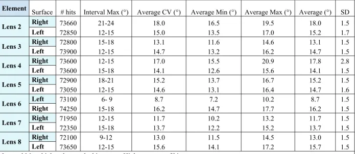
A detailed analysis was carried out regarding the AOI specification of the cameras coatings. Based in Zemax ray tracing, RAL Space provided histograms of the AOI of different rays at each interface air/glass for the spherical camera lenses. Based on these histograms an statistics analysis was carried out. The histograms are in Figure 1 and the statistics summary is shown in Table 3. Where: Interval Max is the highest bar on the histogram. Highest number of hits; Average CV is the average calculated by considering the central value of the bar rank. Hits have the central value;
Average Min is the average calculated by considering the minimum value of the bar rank. Hits have the minimum value; Average Max is the average calculated by considering the maximum value of the bar rank. Hits have the maximum
value; Average is the average of Average CV, Average Min and Average Max; and SD is the standard deviation of the average, not the sample.
Table 3. Histograms data of the number of rays that hit each surface of the camera lenses at different AOI intervals.
Element Surface # hits Interval Max (°) Average CV (°) Average Min (°) Average Max (°) Average (°) SD
Lens 2 Right 73660 21-24 18.0 16.5 19.5 18.0 1.5 Left 72850 12-15 15.0 13.5 17.0 15.2 1.7 Lens 3 Right 72800 15-18 13.1 11.6 14.6 13.1 1.5 Left 73900 12-15 14.7 13.2 16.2 14.7 1.5 Lens 4 Right 73600 12-15 17.0 15.5 20.9 17.8 2.8 Left 73600 15-18 14.1 12.6 15.6 14.1 1.5 Lens 5 Right 72900 18-21 15.2 13.7 16.7 15.2 1.5 Left 73050 12-15 14.6 13.1 16.4 14.7 1.6 Lens 6 Left 73100 6- 9 8.7 7.2 10.2 8.7 1.5 Right 74250 15-18 16.2 14.7 17.7 16.2 1.5 Lens 7 Right 71950 12-15 11.7 10.2 13.2 11.7 1.5 Left 72350 15-18 13.7 12.2 15.2 13.7 1.5 Lens 8 Right 72100 9-12 13.0 11.5 14.5 13.0 1.5 Left 73650 12-15 15.6 14.1 17.2 15.7 1.5
Interval Max: highest bar on the histogram. Highest numer of hits.
Average CV: average calculated by considering the central value of the bar rank. Hits have the central value. Average Min: average calculated by considering the minimum value of the bar rank. Hits have the minimum value. Average Max: average calculated by considering the maximum value of the bar rank. Hits have the maximum value. Average: average of Average CV, Average Min and Average Max
Figure 1. Histograms of number of rays hitting the indicated lens surface at different AOI bins.
From Table 3, it can be seen that there is a wide range of AOIs. The Interval Max values vary between 6° and 24°, the
Average CV between 8.7° and 18°, Average Min between 7.2° and 16.5°, Average Max in 10.2° - 20.9°, Average values between 8.7 and 18°. However, looking at the histograms is clear that are less number of rays at angles larger that 21°. We decided to study the WEAVE case optimizing the coating between 0 and 20° and between 0° and 35°, but to analyze the coating performance at 0°, 10°, 20°, and 35° in both cases.
Several desig best option in achieve the b MgF2. 2.1 FIVE LA gns were devel n terms of perf est solutions. AYERS COA Figu AOI 0 1 2 3
loped and the formance and The designed ATINGS Ta2 ure 2. Reflecta Table 4. Ref I (°) Reflecta PBM2Y Ave 0 0.14 0 0.13 0 0.12 5 0.28
2
advantages o manufacturin d presented he 2O5, SiO2 anance for the fou flectance for dif
ance (%) Y S Max 0.80 0.61 0.24 0.88
2. DESIGN
f each were ev ng. The teamsere are based i nd MgF2
ur glasses of th fferent AOIs for S-LAL9 Ave Max 0.21 1.00 0.19 0.72 0.18 0.48 0.34 1.03
NS
valuated. Here of INAOE an in five layers he red camera. r the 5-layers co S-FPL51 Ave M 0.19 0.8 0.18 0.6 0.17 0.2 0.32 0.9 e we report th nd CIO collab of three mater Five-layers des oating designs. PBL1Y ax Ave 85 0.25 64 0.24 29 0.24 90 0.37 he designs cho orated very cl rials Ta2O5, S signs. Max 0.44 0.43 0.41 0.71 osen as the losely to SiO2 andThe coating depositions a transmittance Elmer® Lam CIO metrolog samples of th performed an
2.2 SIX LAYERS COA
Fi evaporations at least a wi e of the samp mbda 12, calibr gy laboratory he same came nd the average AOI ( 0 20 35 ATINGS Ta2 gure 3. Reflec Table 4. Refle were perform itness sample ple(s). The in rated against y. Here we pr era glasses sh e is used for th (°) Reflecta PBL1Y A 0 0 0
O5, SiO2 and
ctance of three ectance for diff
med at CIO in s is included nstrument used patterns of th resent the Re hown in Tab he rest of the c ance (%) Ave Ma .13 0.4 .14 0.2 .33 0.6 d MgF2 e glasses of the ferent AOIs fo
3. TEST RUNS D
n the Integrit d to evaluate d for this me he Mexican m flectance deri le 1 and 2. Fo calculations. S-FPL51 ax Ave 43 0.14 26 0.13 68 0.30 e red camera. S or the 6-layers cDATA
ty 39 Denton the coating easurement is metrology entit ived from the or each samp e Max 4 0.55 3 0.27 0 0.53 Six-layers desig coating designs. Vacuum Dep quality by m s a spectropho ty CENAM. T e transmittanc le three trans S-LAL9 x Ave 5 0.2 7 0.20 3 0.36 gns. . position Syste measuring aft otometer UV The spectroph ce measureme mittance mea e Max 1 0.49 0 0.29 6 0.47em. In all the fterwards the V-VIS Perkin hotometer is a nt for witness asurements are x 9 9 7 e e -at s e
From the tran the uncoate following: th transmittance wavelengths. Once the men the transmitta These calcul are variations of the actual To be able to reflectance m experimental greater AOIs the process of Figure 4. T r Figure 4 show are removed, nsmittance wi d surface and he actual thic e at an AOI o The transmit ntioned effect ance. lations are str s related to se coating layer o calculate the measured expe data as boun . This type of f deposition it 3.1 Example of the data a
op left: experim right: Re-optim ws the data an the resulting itness sample d the absorpt kness of a g of 0° on on ttance of the i ts are removed aightforward everal paramet s and the des e reflectance erimentally. A dary to fit a t f analysis aids tself. analysis
mental data and mized design tha
nalysis process curve is comp data, it is req tion losses du given sample e surface and ideal coating i d, the reflecta if the measu ters during th ign. at other AOI A re-optimizat theoretical mo s also in estim theoretical refl at fits the exper
s, the measure pared to the th quired to remo ue to the thic is modelled d the other su is divided by ance of the wi ured transmitta he evaporation it is indispen tion through d odel. In this w mating the erro
lectance, after r rimental data. B
ements of tran heoretical refle
ove the Fresne ckness of the
in Zemax co urface uncoat the data mea itness sample ance is very c n process resu nsable to find damped least way we can pr or in the thick removing Fresn Bottom: data ext
nsmission are o ectance based el losses due t e witness sam onsidering an ted. Zemax p surements ob can be calcul close to the de lting in differ d the design c squares of th redict the ac kness of each nel reflections fr trapolation to n obtained expe on the AR de to the interfac mple. The pr ideal coating provides valu btained at norm lated as R = 1 esign one. In rence between corresponding he design is do ctual coating layer, provid
rom the second non-normal AOI
erimentally, Fr esign. The init
ce glass/air of rinciple is the g of 99.9% ues at specific mal incidence 1-T where T is practice there n the thickness g to the actua
one, using the behaviour a ding insight o surface. Top I. resnel effects tial design is f e % c e. s e s al e at f
modified to match the experimental data by a re-optimization. Finally, the experimental data can be extrapolated to alternative AOIs based on the theoretical model.
3.2 REPEATIBILITY
CIO has worked intensively to characterize the Integrity 39 Denton Vacuum Deposition System. There are several factors. In Figure 5 we show the reflectance results for two PBM2Y witness samples in two different depositions for the same coating prescription. Samples L62 y L64 were coated in the first run and L63 y L65 in the second one. In Table 5 the average reflectance for different angles of incidence is reported. These results include all the experimental and measurements errors.
Figure 5. Reflectance obtained in different coating runs.
Table 5. Average reflectance obtained in two different runs for the same coating design.
Sample Average R (%) 0° 10° 20° 35° L62 0.20 0.21 0.26 0.56 L63 0.20 0.21 0.26 0.55 L64 0.24 0.23 0.24 0.47 L65 0.23 0.22 0.22 0.42 0 0.2 0.4 0.6 0.8 1 1.2 1.4 1.6 570 670 770 870 970 R (%) Wavelength (nm) PBM2Y Samples @ 0
°
L62 L63 L64 L654.1 LENS 6 AND LENS F F A 7 (PBM2Y) Figure 6. Refl Figure 7. Refle Table 6. AOI 0 10 20 35 lectance obtaine ectance obtaine . Average refle Surfac Ave 0.29 0.27 0.23 0.38
4. FINAL COAT
ed for PBM2Y ed for PBM2Y ectance obtained Reflec ce 1 Max 1.07 0.86 0.45 1.02TINGS
Y Lens 6 and Le Lens 6 and Le d for Lens 6 an ctance (%) Ave 0.32 0.29 0.23 0.36 ens 7. Surface 1 ens 7. Surface 2 nd Lens7. Surface 2 Ma 1.3 1.1 0.6 1.0 1. 2. ax 35 12 62 044.2 LENS 4 (PBL1Y) A Figure 8 Figure 8. Ta AOI 10 20 27 35 . Reflectance o Reflectance o able 7. Average Surfac Ave 0.21 0.27 0.36 0.58 obtained for PB . obtained for PB e reflectance ob Reflec ce 1 Max 0.65 0.82 1.03 1.45 BL1Y Lens 4. BL1Y Lens 4. btained for Lens
ctance (%) Ave 0.15 0.19 0.26 0.44 Surface 1 Surface 2. s 4. Surface 2 Ma 0.4 0.5 0.7 1.1 ax 43 57 77 17
4.3 LENS 8 (SLAL-9) Figure 5. H A Figure 9. Figure 10. Histograms of Ta AOI 10 20 27 35 Reflectance o Reflectance o f number of ray able 8. Average Surfac Ave 0.26 0.26 0.29 0.57 obtained for SL obtained for SL ys hitting the ind
. e reflectance ob Reflec ce 1 Max 0.50 0.48 0.44 1.05 LAL-9 Lens 8. LAL-9 Lens 8. dicated lens su btained for Len
ctance (%) Ave 0.15 0.14 0.13 0.30 Surface 1. Surface 2. urface at differen ns 8. Surface 2 Ma 0.3 0.2 0.2 0.6 nt AOI bins ax 32 25 25 65
5. CONCLUSIONS AND FURTHER WORK
Great amount of R&D has been done in the determination of the most suitable material combination and optimal optical properties of AR coatings for the specific case of WEAVE. The requirements are large AOI and a medium size spectral range. Red Camera coatings are soon to be finished and the Blue Camera along with its AR coatings are under
development.
.
REFERENCES
[1] Dalton, G., et al. "Construction progress of WEAVE: the next generation wide-field spectroscopy facility for the William Herschel Telescope". Proc. SPIE 10702, Paper No. 10702-47 (2018).
[2] Dalton, G., et al., "Final design and progress of WEAVE: the next generation wide-field spectroscopy facility for the William Herschel Telescope," Proc. SPIE 9908, pp. 99081G (2016).
[3] Izazaga, R., et al. "The polishing of WEAVE spectrograph collimator mirror", Proc. SPIE 10706, Paper No. 10706-18 (2018).
[4] Izazaga, R., et al. "WEAVE spectrograph camera: the polishing of the spherical lenses", Proc. SPIE 10706, Paper No. 10706-127 (2018).
[5] Hidalgo, A., et al. "Test plates design and manufacturing for the camera lenses of the WEAVE spectrograph", Proc. SPIE 10706, Paper No. 10706-130 (2018).