Procedia Technology 25 ( 2016 ) 974 – 981
ScienceDirect
2212-0173 © 2016 The Authors. Published by Elsevier Ltd. This is an open access article under the CC BY-NC-ND license (http://creativecommons.org/licenses/by-nc-nd/4.0/).
Peer-review under responsibility of the organizing committee of RAEREST 2016 doi: 10.1016/j.protcy.2016.08.190
Global Colloquium in Recent Advancement and Effectual Researches in Engineering, Science and
Technology (RAEREST 2016)
A simulation based study of flow velocities across cross flow
turbine at different nozzle openings
Shashi Chichkhede, Vinay Verma, Vivek Kumar Gaba andShubhankar Bhowmick*
Department of Mechanical Engineering, NIT Raipur, 492010, India
Abstract
The present work reports CFD based investigation of the effect of design parameters on the flow velocities of a cross flow turbine (CFT). Best described as an impulse type turbine with partial admission of air, cross flow turbines meet the demand for an efficient turbine to run at low head that is also easy to manufacture. The design of cross–flow turbine is unique due to the generation of power during two stages. This type of turbine is often used in small hydropower plants located in less–developed countries. The design parameters of CFT that can be varied to increase overall efficiency and power output of the turbine are water inlet angle, blade angle at inlet and outlet. In the present work the design parameters are varied for different nozzle openings and simulated using CFD. A full 3-D steady state flow simulation of the cross-flow turbine is performed including casing, runner and nozzle assembly.
© 2015 The Authors. Published by Elsevier Ltd.
Peer-review under responsibility of the organizing committee of RAEREST 2016.
Keywords:Cross flow turbine, nozzle opening, blade angle, CFD.
1. Introduction
Hydropower being an important source of renewable energy, has expanded rapidly over the past decades. The main focus lies in utilizing the available resources as efficiently as possible. The developing nations lack resources to utilize them. Therefore, a need for a more simple, but efficient, way to harness the available resources is much
* Corresponding author. Tel.: +91 9575955040
E-mail address:[email protected]
© 2016 The Authors. Published by Elsevier Ltd. This is an open access article under the CC BY-NC-ND license (http://creativecommons.org/licenses/by-nc-nd/4.0/).
needed. The cross–flow turbine, being one such possibility, is mostly used in developing countries due to ease in fabrication in the limited capacity workshops due to its simple design. Hence CFT has, in recent times, attracted special interest as a different kind of small hydro turbine.
Mockmore and Merryfield [1] proposed an appropriate parameter based design of the cross flow turbine and reported that CFT can be operated efficiently over a wide range of openings and established that maximum efficiency occurs at a constant speed irrespective of gate openings at constant head. Hamierl [2] presented a series of experimental test performed in the lab set-up of CFT and reported test data of turbine efficiency and power and its dependency on design variable and operating parameter. Verhaart [3], compared Francis turbine and CFT for equivalent initial condition i.e. in size and specific speed, and observed that energy output of CFT is higher than Francis turbine. Khosrowpanah et al [4] investigated the effect of the number of blades, the runner diameter, and the nozzle entry arc under flow/head variations on the turbine performance and reported that the maximum efficiency of the CFT at any flow/head combination increases as the nozzle entry arc increases or the aspect ratio of the runner decreases. Desai and Aziz [5] reported experimental investigation for measurements of torque, rotational speed, flow rate, and total head in physical model of turbines and nozzles and identified the impact of the different parameter on the turbine efficiency.
In a recent work, design of high efficiency CFT for hydro-power plant is proposed by Nasir [6] where in all design parameters of cross-flow turbine were calculated at maximum efficiency and maximum efficiency 88% was reported for different head and water flow rate. In another recent work, Sammartano et al [7] reported an optimal design of Banki-Michell turbine using computational fluid dynamics testing. Maître et al [8] presented a 2-dimensional hydrodynamic optimization of channeling devices for cross-flow water turbines to optimize a symmetrical two-foiled channeling device for vertical axis cross-flow water turbines. Gudukeya and Madanhire [9] proposed methods of efficiency improvement of pelton wheel and cross-flow turbines in micro-hydro power plants. Kim et al [10] presented a CFD study of a ducted cross flow turbine for high efficiency tidal current energy extraction using a cross-flow turbine wherein the bi-directional flow of tidal currents is used to drive a uni-directional cross-flow turbine. The performance of the device is studied numerically using the commercial ANSYS-CFX code. Ho-Yan and Lubitz [11] evaluated the performance of cross-flow turbine for low head application. Zanette et al [12] reported that the mechanical stress sustained by the CFT blades depends on the basic geometry specifications, its rotational speed, the exact geometry of the blades and the velocity of the upstream water current.
In the present work, the effect of design parameters on velocity of flow across cross-flow turbine is computed using CFD based simulation. The key design parameters involved in the study are blade angles, the angle of water entry to the runner, and different nozzle opening.
Nomenclature
U Peripheral velocity, m/s V Absolute velocity, m/s W Relative velocity, m/s α Water inlet angle β Blade angle
Subscript
1 Water entering the first stage 2 Water leaving the first stage 3 Water entering the second stage 4 Water leaving the second stage
2. Geometry and CFD model
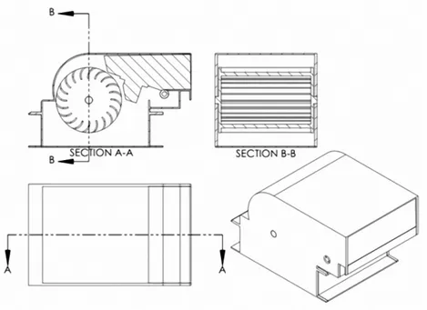
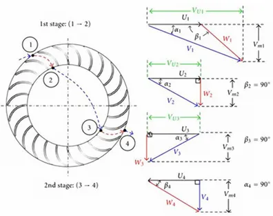
The present work is carried out on design specifications reported in [13]. Constructional feature of such turbines comprises of two major parts, the runner and the nozzle and is shown in Fig. 1. The runner is made up of at least two circular side walls with blade fixed to the inside walls. The blade has circular cross-section and make a specific angle to the outer periphery ‘β’. The nozzle has the rectangular cross section and it directs the flow into the runner at an angle of attack ‘α’. The water flows through the rectangular cross–section nozzle and enters the runner, where the first stage power is generated. In the second stage, the water, then, flows diametrically through the center of the runner, before it hits the blades on its way out, generating power again. The turbine has a simple design, which is economical and easy to manufacture. The assembly of CFT is shown in Fig. 2.Velocity diagrams give an indication of the magnitude and direction of the velocity of the water. No loss through the inside of the runner is assumed, which gives equal diagrams at the outlet of the first stage and inlet of the second (Fig. 3). In addition, it is assumed that energy extracted from the water at the turbine outlet is fully utilized, hence no tangential component of the absolute velocity is considered. According to Euler’s equation, upon considering the variation of the velocity triangles from runner inlet to outlet of the 1st stage and then from runner inlet to outlet of the 2nd stage, the output power transferred from the flow to the rotor/runner can be calculated.
Fig. 1. Sectional view of runner and nozzle geometry.
Navier-Stokes equations, being fluid flow formulation of mass, momentum and energy conservation laws is solved while simulating the flow using CFD. The equations are provided with fluid properties. A particular problem is defined with the help of its geometry, boundary and initial conditions. To predict turbulent flows, time-averaged effects of the flow turbulence on the flow parameters are considered. Flows in models with rotating parts are computed in coordinate systems attached to the models rotating parts, i.e. rotating with them, so the models' stationary parts must be axisymmetric with respect to the rotation axis.
Fig. 3 Velocity diagram for stage 1 and 2 of CFT
For internal flows, flow simulation offers the following two options of specifying the flow boundary conditions. One of which is imposition at the model inlets and outlets while the other is to specify them by transferring the results obtained in another simulation. With the first option, all the model openings are classified into "pressure" openings, "flow" openings, and "fans", depending on the flow boundary conditions which one intends to specify on them. A "pressure" opening boundary condition, which can be static pressure, or total pressure, or environment pressure is imposed in the general case when the flow direction and/or magnitude at the model opening are not known a priori, so they are to be calculated as part of the solution. A "flow" opening boundary condition is imposed when dynamic flow properties are known at the opening. If the flow enters the model, then the inlet temperature, fluid mixture composition and turbulence parameters must be specified also. The pressure at the opening will be determined as part of the solution. Flow simulation solves the governing equations with the finite volume method on a computational mesh designed in the chosen coordinate system. Values of all the physical variables are stored at the mesh cell centers. Due to the finite volume method, the governing equations are discretized in a conservative form. The spatial derivatives are approximated with implicit difference operators of second-order accuracy. The time derivatives are approximated with an implicit first-order Euler scheme. The viscosity of the numerical scheme is negligible with respect to the fluid viscosity.
3. Results and discussion
The present study is conducted for cross-flow turbine [13] consisting of a steel casing, an adjustable nozzle and runner. The nozzle has rectangular cross-section area. The nozzle entry arc on this turbine is 120°. The flow simulation has been run at a constant rotational speed of 350 rpm and head of 5 meter is used. The results are first validated with experimental results reported in [13] and a reasonable agreement is observed as reported in Table 1. The study is, then, further extended to investigate the effect of different design parameters. Using CFD simulation,
velocity profiles are obtained for different design condition. The effects of blade angle at inlet, nozzle openings and water inlet angles arestudied parametrically.
Table 1. Validation of the present study.
At 350 rpm, 5 meter Head Reference [13] Present Study % error At 40% nozzle opening 64.0 60.9 4.8% At 60% nozzle opening 72.9 67.5 7.4% At 80% nozzle opening 76.8 70.7 7.9%
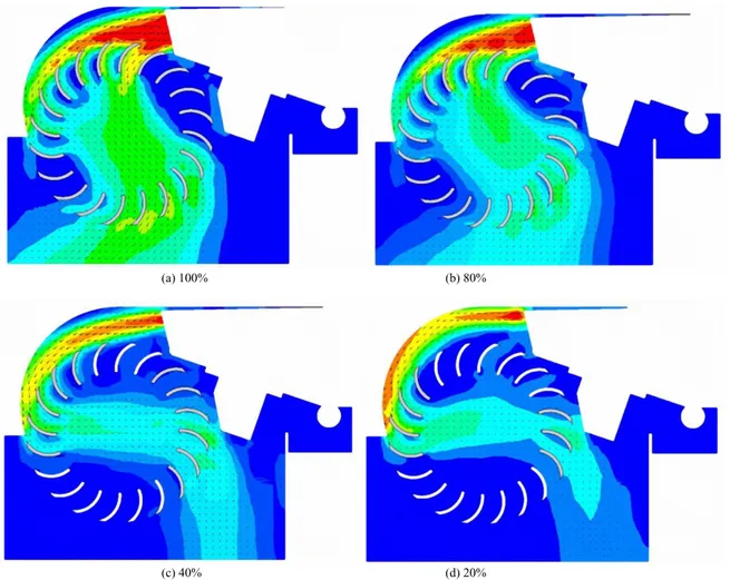
The inlet angle β1 of blade has been varied from 24° to 30° and an outlet angle, β2, is assumed as 90°. The water inlet angles are varied at 12°, 15° and 18° and nozzle opening is varied by 20%, 40%, 60%, 80% and 100%. The nozzle entry arc on this turbine is 120°. The runner consists of 24 blades symmetrically arranged between two circular plates along the plate periphery. The velocity distribution across the CFT runner for different nozzle openings at 100 %, 80 %, 40 % and 20 % is shown in Fig 4(a-d) respectively.
(a) 100% (b) 80%
(c) 40% (d) 20%
Fig. 4 (a-d). Velocity distributions across CFT runner at different nozzle openings at 12 ° inlet angle
The velocity cut plots shown in Fig. 4 (a-d) report that with increasing nozzle opening, flow rate increases and the turbine works well for large nozzle openings. The water enters the runner close to the nozzle outlet, leading to a
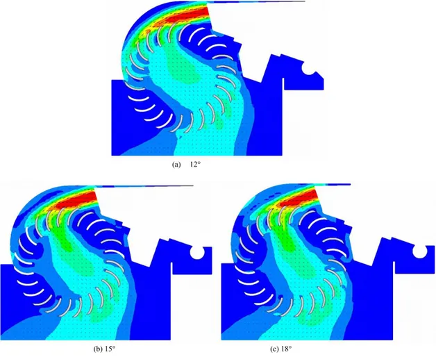
cross flow entering the inside of the runner at a short distance from the nozzle. This gives good conditions for the flow, as the direction of the absolute velocity when entering the second stage corresponds well with the blade inlet angle. With decreasing nozzle opening, the cross flow enters the inside of the runner further away from the nozzle. This gives a direction of the cross flow which corresponds poorly with the inlet angle of the blades at the second stage, which increases the incidence losses and hence may yield lower efficiency. In Fig 5 (a-c), the velocity distribution across the CFT runner for different water inlet angles are plotted. It is evident from Fig 5 (a-c) that flow trajectory at different water inlet angle lead to different flow volume thereby affecting the efficiency directly. At low inlet angle, the trajectory is such that larger volume of water covers more number of blades thus increasing the power of the turbine. The maximum efficiency tends to decrease with the increasing in the first-stage water inlet angle in the range of 12°-18°. This is due to the effect of the corresponding increase in the first-stage blade inlet angle (β). This leads to the shifting of the water jet towards the shaft center. It results in a decrease in the turning moment at the shaft center due to the water jet. Hence, there is a reduction in the output power and efficiency.
(a) 12°
(b) 15° (c) 18°
Fig. 5 (a-c). Velocity distributions across CFT runner for different inlet angles at 60 % nozzle opening
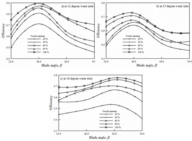
The effect of blade angle, nozzle opening and inlet angle on efficiency has been studied extensively by means of parametric flow simulation and the dependence of the efficiency on the design parameters is plotted in Fig. 6 (a-c).
Fig. 6 (a-c). Effect of blade angle at different water inlets and nozzle openings on efficiency of cross flow turbine at 350 rpm and 5 meter head
4. Conclusion
A 3-D flow simulation of the cross-flow turbine is reported and the influence of nozzle opening and water inlet angle has been analyzed. The velocity flow fields for different combinations of the above parameters are plotted to gain a good insight into the flow pattern inside the CFT. The present study details the dependence of turbine efficiency on design parameters. An investigation, which otherwise is, not economically viable experimentally, has been performed parametrically by flow simulation through the CFT. The results reveal dependence of efficiency on blade angle at different nozzle openings. The optimum blade angle value is observed to increase with increasing inlet angle for the given geometry. The plotted results could very well be used as design data by practicing engineers.
References
[1] Mockmore CA and Merryfield F. The Banki water turbine, Engineering environmental station, Bulletine series no.25. Oregon state system of higher education Oregon state college Corvalis; 1949.
[2] Hamierl LA.The cross flow turbine. Water power engineering.12,5-13;1960.
[4] Khosrowpanah S, Fiuzat AA, and Albertson ML.Experimental study of cross flow turbine. J. Hydraul. Eng., 114. 299-314; 1988. [5] Desai VC and Aziz NM. Parametric evaluation of cross flow turbineperformance. J.Energy Eng., 120. 17-34; 1994.
[6] Nasir BA. Design of High Efficiency Cross-Flow Turbine for Hydro-Power. Int. J. Engg. Adv. Tech. 2. 308-311; 2013.
[7] Sammartano V, Aricò C, Carravetta A, Fecarotta O and Tullio Tucciarelli. Banki-Michell Optimal Design by Computational Fluid Dynamics Testing and Hydrodynamic Analysis. Energies. 6. 2362-2385; 2013.
[8] Maître T, Roa AM, Pellone C, Achard J.Numerical 2d hydrodynamic optimization of channelling devices for cross-flow water turbines. U.P.B. Sci. Bull. 72. 125-132; 2010.
[9] Gudukeya L,Madanhire I.Efficiency improvement of pelton wheel and crossflow turbines in micro-hydro power plants: case study. Int. J. Engg. Comp. Sci. 2. 416-432; 2013.
[10] Kim I, Watal J, Ahmed MR, Lee Y. CFD study of a ducted cross flow turbine concept for high efficiency tidal current energy extraction. J. Asian Wave Tidal.Conference Series. 400-404; 2012.
[11] Ho-Yan B, Lubitz WD. Performance evaluation of cross-flow turbine forlow head application.World Renewable Energy Congress. 1394-1399; 2011.
[12] Zanette J, Imbault D, Tourabi A. A design methodology for cross flow turbines. Renewable Energy. 35. 997–1009; 2010. [13] Eve Cathrin Walseth. Investigation of the flow through the runner of a cross-flow turbine. MS Thesis, NTNU, 2009.